Design of backdoor
DESIGN OF BACK DOOR(TAILGATE) USING CATIA V5
Introduction:
The back door is simply door at the back side of the car and the door design varies with different segment and purpose here back door of a SUV model has been taken and in SUV type the rear door is streamlined and is not like sedan class and designing a rear door follows various considerations and it should also ensure DFM and DFA and also critical in ensuring the boot space of the car and also has various subcomponents like bake lights and indicators and rear wiper and rear windscreen and in this report we are going to see the various design considerations for an effective tailgate design
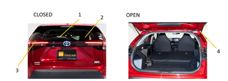
1- Rear wiper
2-rear windscreen
3-bake light with indicator
4-gas spring
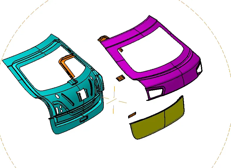
Components of rear
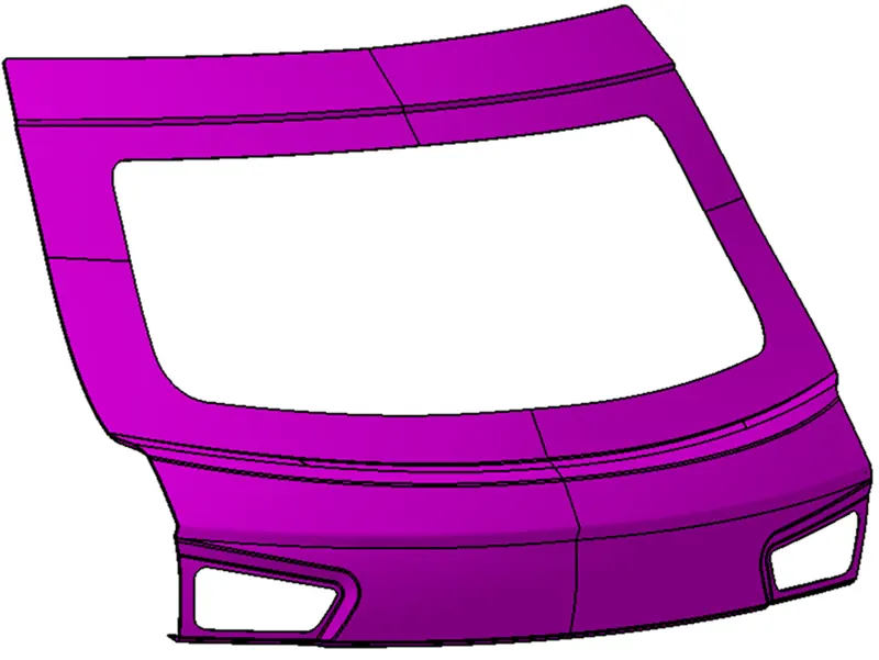
- Upper panel outer
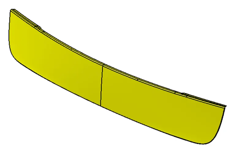
- Lower panel outer
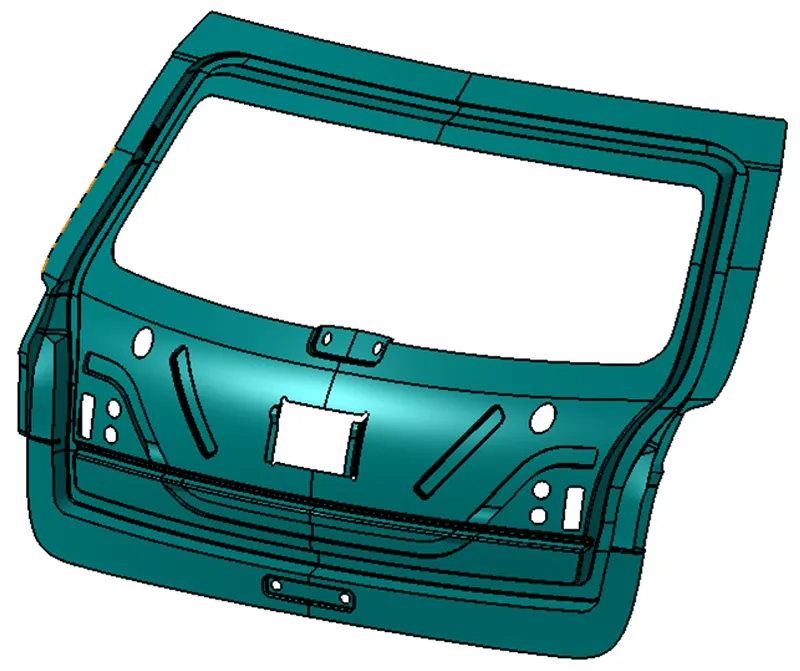
- Inner panel
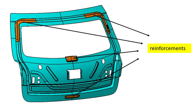
- Reinforcements
Upper panel outer
the upper panel outer is as per the give class A surface and is decided by the styling team and the styling team also design with input from the vehicle intergration for the visual parmeters and master sections to avoid clash with other components and also gap and flushes reqirements
Lower panle outer
the lower panel outer is also same as the upper panel design
Inner panel
The inner panel is simply reinforcement given to the outer panels and it also has provisions for fitment of other components like the gas sping mounting, tail lamp mounting, wiper mounting and it also has sealing flange to mount beading which aids in sealing the inner from outside dust and water
Reinforcements:
the reinforcements are just inner provisions given to improve the strength locally so that the part shall withstand the load applied and the various reinforcements with the inner panel are shown below and thickness of about 0.75mm is maintained throughout
- striker reinforcement
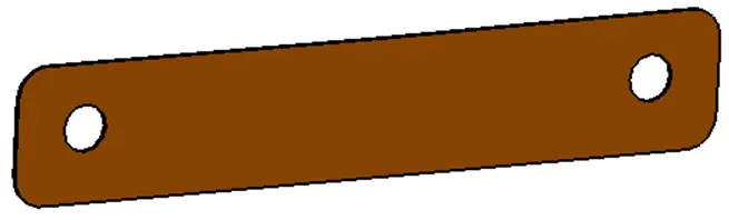
- wiper motor reinforcement
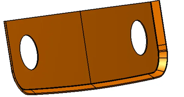
- hinge and gas stay reinforcements are given combined
- inner panel with reinforcements
The various design considerations for designing the back door
- DFM - Design For Manufacturing
- DFA - Design For Assembly
- Ncap regulation
DFM
the DFM is simply various constrains followed to ensure the ease of manufacturability of the product and so the basic rules to be followed for BIW parts are as follows
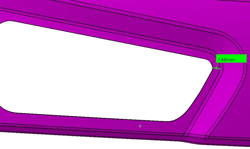
- gap between edge to emboss to be min 6-8mm
- draft angle min 7 deg
- fillet should be min 3mm + thickness of the part
- min land area between adjacent parts should be same 6-8mm
- flange for spot welding
conformations for DFM
1.OUTER PANEL UPPER
- the gap criteria is met properly(shown the lest space available area)
- draft analysis of outer panel-7deg min from tooling axis
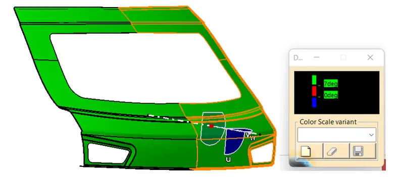
from above result the draft is confirming
- Flange for spot welding
It is given the distance between the center of spot weld to edge
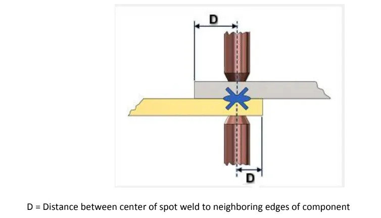
D= 2* spot weld diameter
the min overlap for the spot weld is 8mm
hence 2d=2*8=16mm(min)
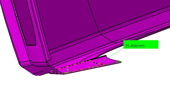
here we get more than sufficient flange length for spot welding and is confirming
2.LOWER PANEL OUTER
- Gap and land area for the lower panel confirmation
result - as there is not any holes or embossed in the lower panel outer it is confirming
- Draft analysis - min 7 deg
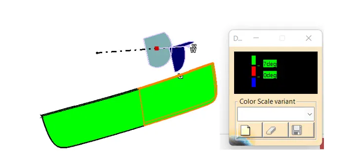
the draft is cofirming
- Flange for spot welding
as from above the min flange length required is about 16mm
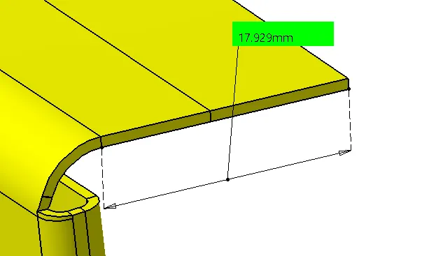
the consideration is confirming
3. INNER PANEL
- the land area clearance of 6-8mm
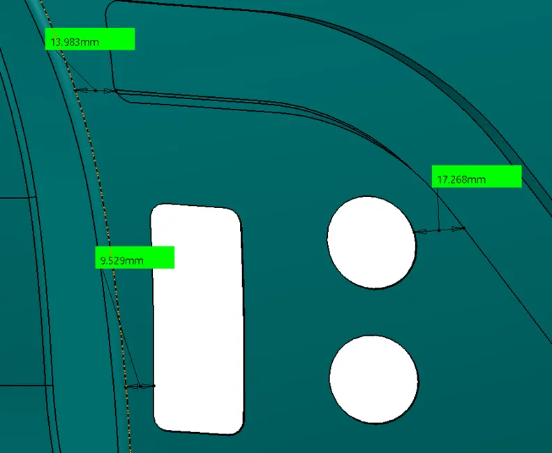
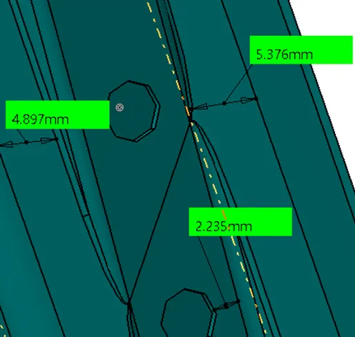
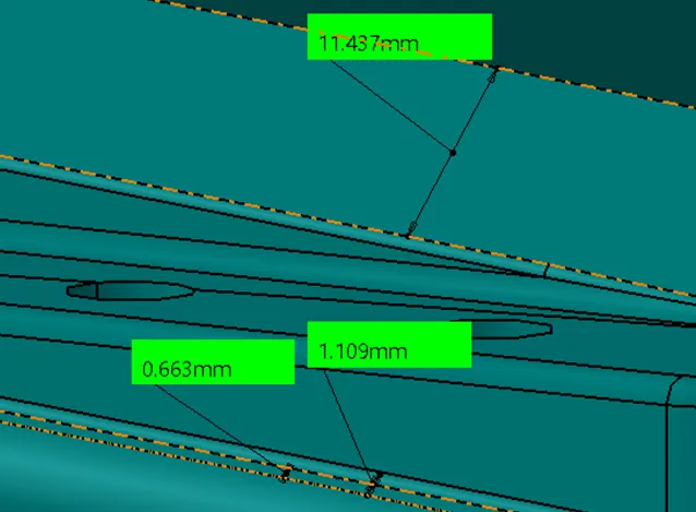
from above tha land area is confirming in most of the case yet at the hinge and gas spring mounting areas there is a min clearance available and these min as the flange in these areas are minimum
- DRAFT
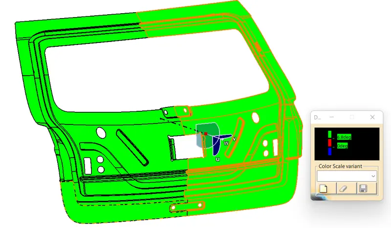
therfore the draft is confirming in single operartion and is not matching only in the masting flange area and it is also manufacturable as is done in secondary operation
- RELIEFS
reliefs are given to avoid sharp corners in the part
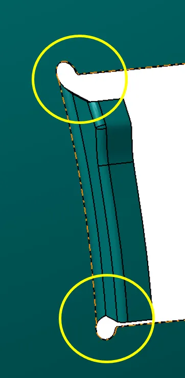
therfore the relief is confirming
DFA
the design for assembly is the considreration for the assembly of different components together in to a seperate aggregate and the considerations in this case are as follows
- hinge and striker position
- assembly of outer upper, outer lower and inner panel
- mountings for gas stay and hinge
- design for space consideration
confirmations for DFA
1.hinge and striker position
the criteria for the hinge and striker position by drawing a circle to the center point of the two hinges and the positioning the stiker based on drawing a center line to the striker and making the line perpendicular to the circle
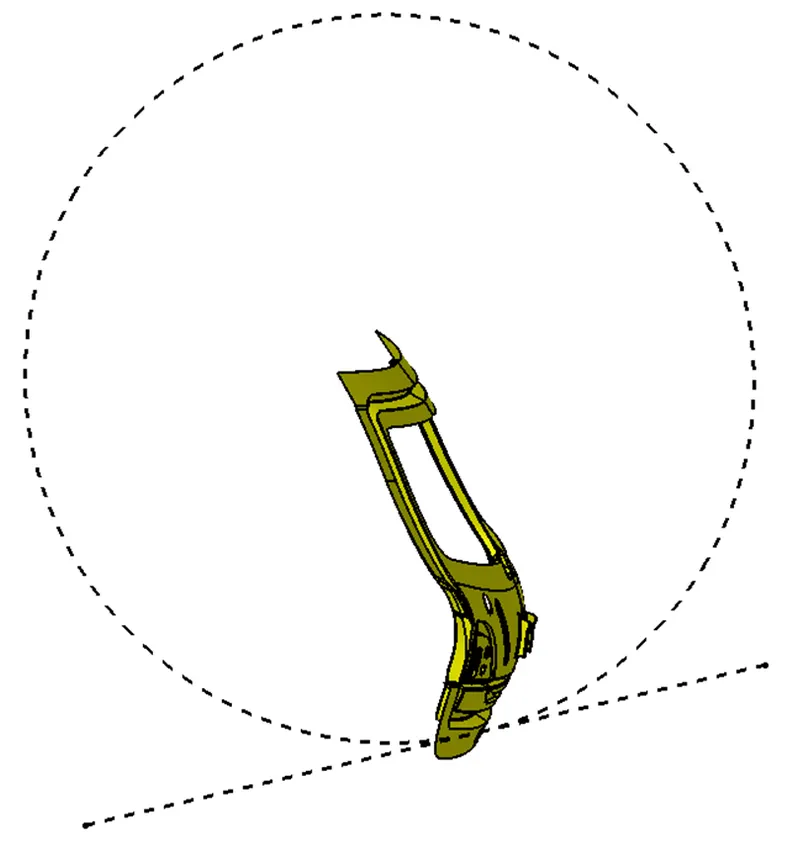
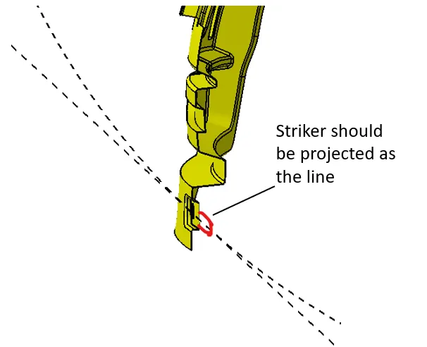
therefore the mounting of stricker position is confirming
2.ASSEMBLY OF OUTER UPPER , OUTER LOWER AND INNER PANEL
The assembly of the outer upper , lower and inner is done by the following steps
- first the outer lower and upper are spot welded and as the flanges confirming DFM is shown above and the min clearance of 0.4mm is maintained
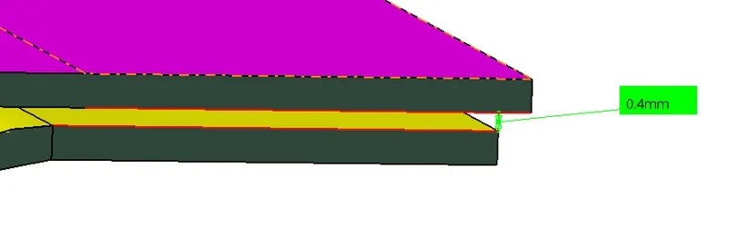
- then the outer upper and lower and inner panel are mounted together by hemming and also by using the mastic as shown below
HEMMING DATA
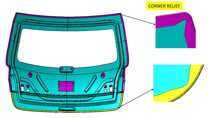
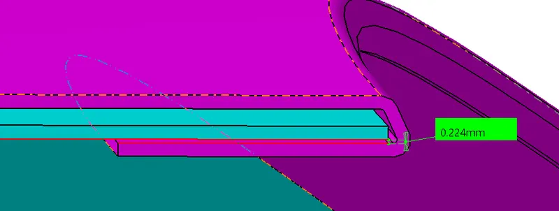
hemming is a phenomena of joining different panels just by bending one panel to about 180 deg to the another panel and it also requires coner reliefs and 0.2mm clearance
confirmation of hemming in design given below
corner relief
hemming clearance
MASTIC JOINING
mastic joining is a technique where joining will not be visible on the out side and this is paricularly used on A surface joining
it also has certain rules to be followed
- there should be a gap of about min 5mm between the panels as the mastic is like a filler material and it bulge after condensation and it also acts for NVH purpose
confirmation in design
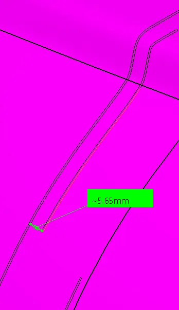
3.MOUNTING OF GAS STAY AND HINGE
HINGE MOUNTING:
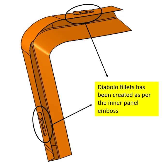
the hinge mounting is in the default top side and for proper engagement of screws in this location flat faces are ensured and this is done by creating diabolo fillets with local flat faces
confirmation in the design
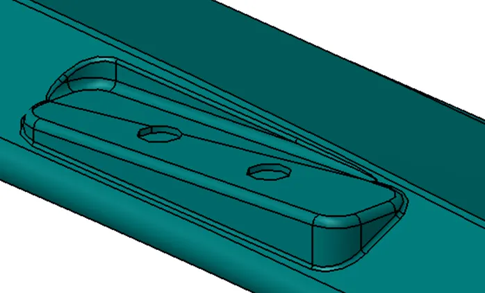
GAS STAY MOUNTING
the gas stay mounting plays a crucial role as its determines the gas stay force and so here i have fixed the door side mounting and body side mounting will be determined base on the following formula and here also we have used the diabolo fillet for flat face - screw engagement
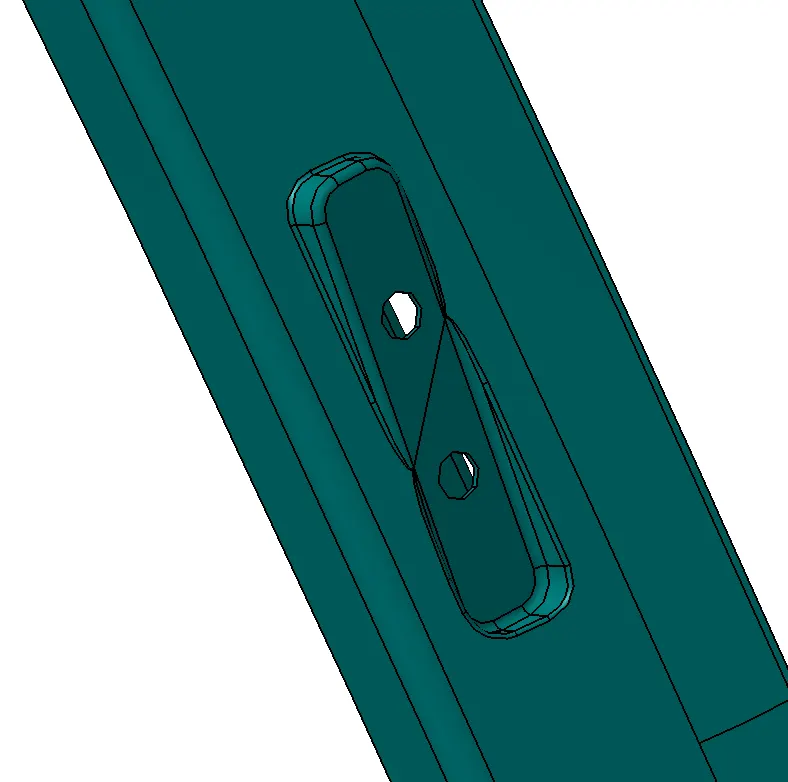
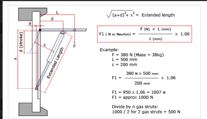
4.DESIGN FOR SPACE CONSIDERATION
the design of the back door also takes into consideration of boot space availability and here we have designed teh inner panel in a sense to increase the boot space as much as possible
- here i have created liitle bending of inner panel and i have also created emboss in the joinery area which have increased the boot space availability
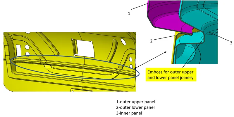
- the NVH emboss is also created inside of the joinery emboss which have resulted in a effeftive space avilability in the design
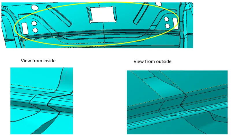
NCAP IMPLEMENTATION
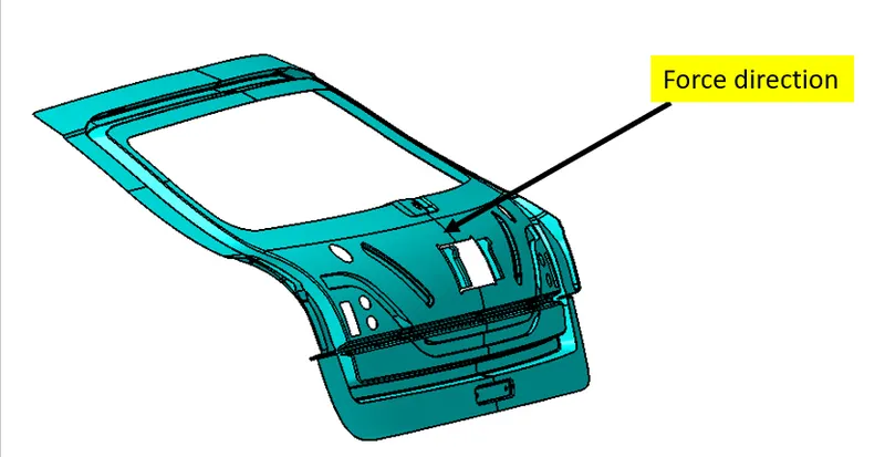
here i have also created emboss with the inner panel to meet the safety regulations and force disssipitations
- force direction
- force travel
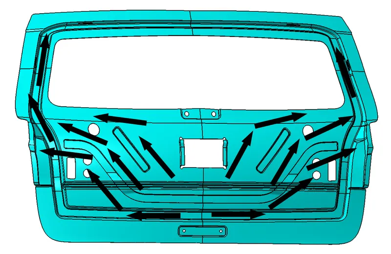
from the above image we can say that the force gets disippated towards the gas stay mounting and hinge mounting and also body sides reducing the direct impct to the passengers
EXPLODED VIEW OF REAR DOOR
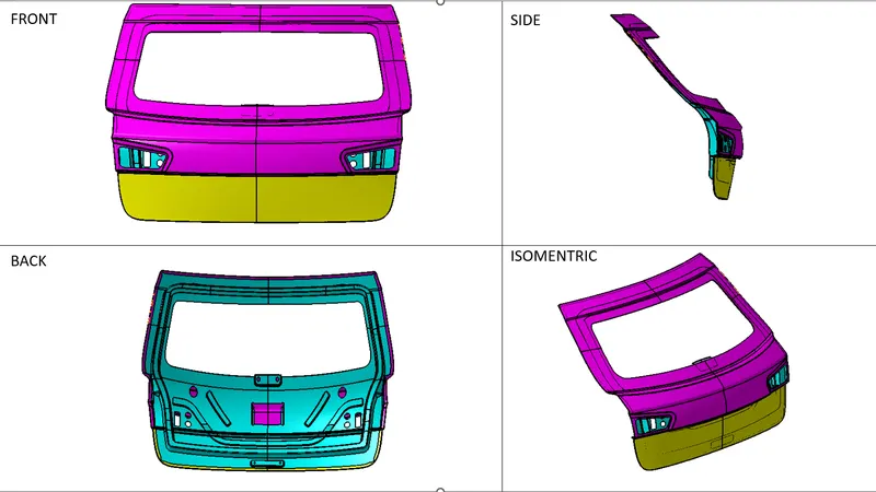
FINAL ASSEMBLED PART
CONCLUSION:
thus i have designed the various parts of the rear door in catia using the given class a input and following the design rules for the BIW components and also confirming my design to DFM , DFA and NCAP regulations