Week 9 - Project 1 - Door Applique Design with Engineering Features
DOOR APPLIQUE SOLID CREATION , DRAFT ANALYSIS AND ALSO ATTACHMENT FEATURE CREATION
1.SOLID CREATION
TOOLING AXIS
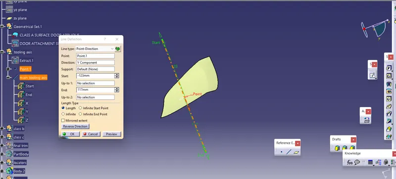
- from the given class a surface it can be seen that from y axis there is no parallel face to the line
- so a point is created on A surface at 0 and a line is created along the y axis
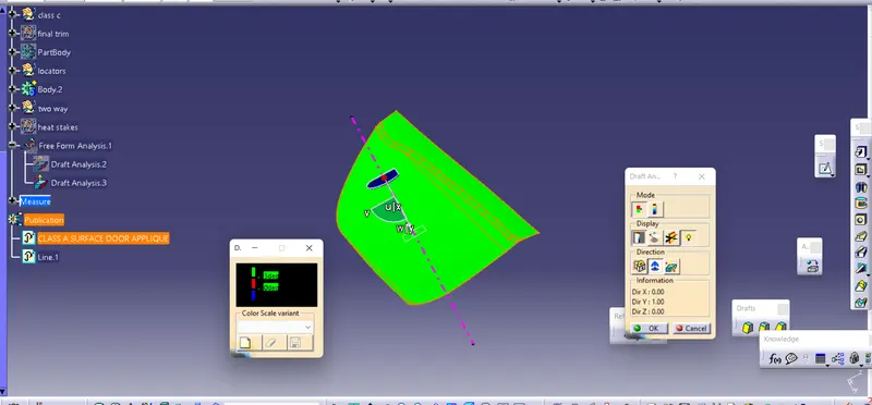
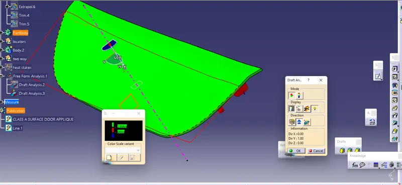
- draft analysis along the tooling axis and the green colour ensures the clearing of the class a along the axis
CLASS B CREATION
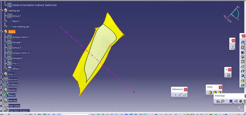
- the two faces of the class A are first extracted untrimmed extrapolated and are trimmed together and finally they are offseted to about 2.5mm
CLASS C CREATION
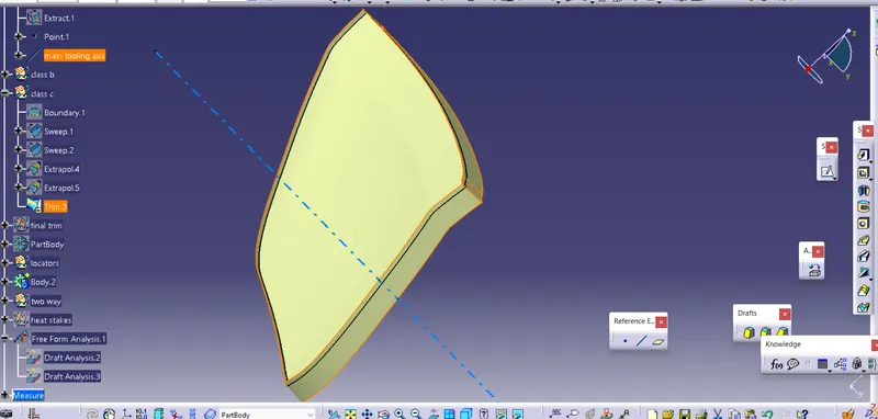
- the class c is created by two subelements and are also extended in both direction because of sharp corners in the edges
- then the subelements are also created with the draft of 3def
- finally the two subelements are trimmed together
FINAL TRIM
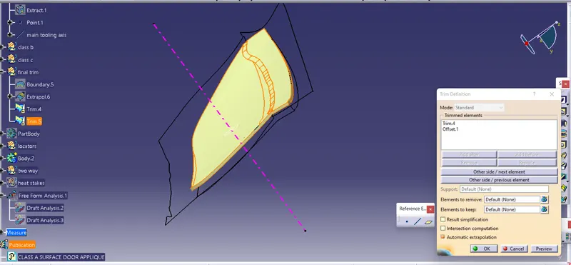
- then the class A is extrapolated and is then trimmed with the class c
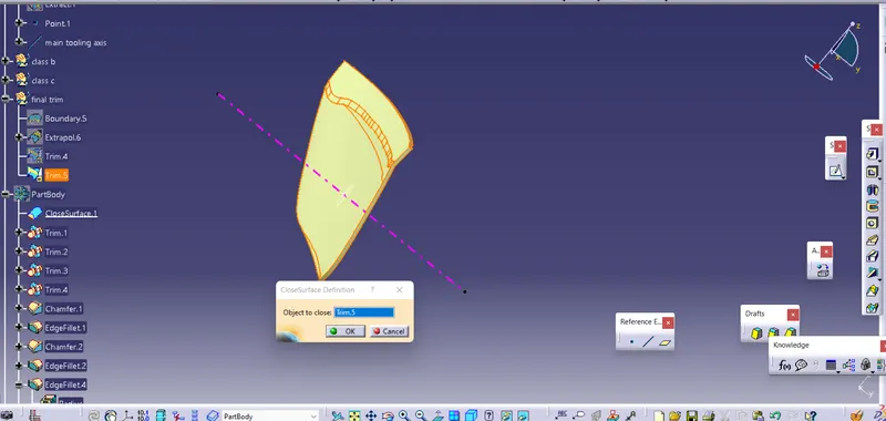
- then this trim is further trimmed with the class B to create the closed surface
- then solid is formed out of this using closed surface command
DRAFT ANALYSIS OF FINAL SOLID
ATTACHMEN FEATURE CREATION
1.LOCATORS CREATION
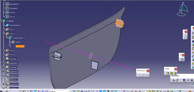
- first the four way locators are creted and this arreats the 11 degrees of freedom and the four way locators are nothing but the rib fearture and this is created using the rib design rules i.e 0.4 *thickness
- the sketch is create using the referance surface and draft is also given 0.5 deg as per rules
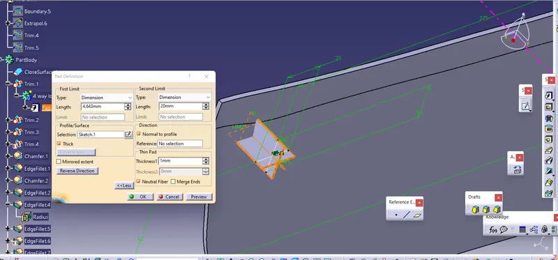
- the another 4 way locator is created using the translation option
TWO WAY LOCATORS
- two way locator is also created using the rib design rules and the sketch is creted using the referance surface as shown in picture above and draft of 0.5 deg is given
HEAT STAKES
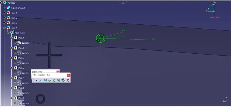
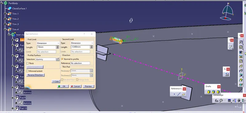
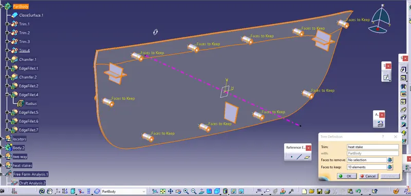
- the heat stakes created for the purpose of plastic welding and easy way of fastening the component into another
- the heat stake is like a hollow cylinder block and this gets inserted into the another component and is welded
- the height differance between the stakes and the locator is maintained as location is the first in order
- the major rule followed here is based on the screw boss as the thickness should be maintained 0.6 * thickness
- the draft of 0.5 deg is also given to the stakes as per rules
DRAFT ANANLYSIS OF B SIDE ATTACHMENT FEATURES
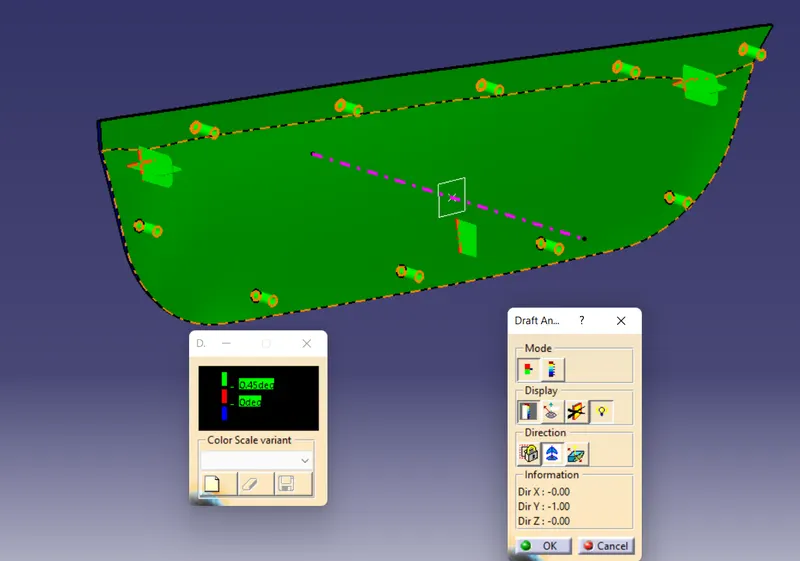
- this image shows that the green colour areas has a minimum draft of 0.45 and above
- henceforth these features will ne cleared in main tooling axis