Hood design-Week 2
COMPLETE DESIGN OF HOOD ASSEMBLY USING THE MASTER SECTION AND ASSEMBLIN WITH PROPER POSITION OF LATCH AND STIKER AND GIVING REINFORCEMENTS AND FOLLOWING THE STANDARDS OF DIFFERENT APPROACH
INTRODUCTION
The hood is the outer cover of an engine in a car and is and it becomes crucial as it directly impacts the safety standards and NVH(Noise vibration and harshness) and also the drag of the car and so it is to be effectively designed and in this report we are going to see about the various approaches towards the perfect design and also the various rules predefined for the particular aspect and also we are going to see about the assembly rules for proper positioning of the hing and striker in a hood and also following the master section in the design
Parts of hood
- Outer panel
- Inner panel
- Striker and Striker reinforcement
- Hinge assembly and Hinge reinforcement
- Outer panel
This is the outer aesthetic structure visible to the customer and so it need to be appealing and the appearance cannot be compromised and only the drag and size of the outer panel is considered and the styling engineer does it
Class a
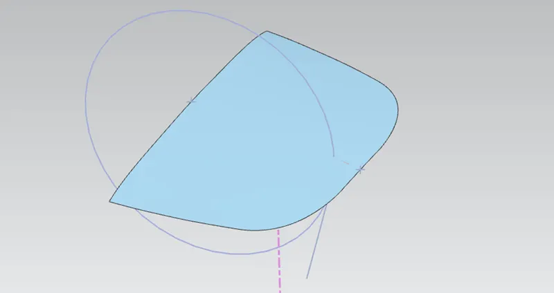
The outer panel
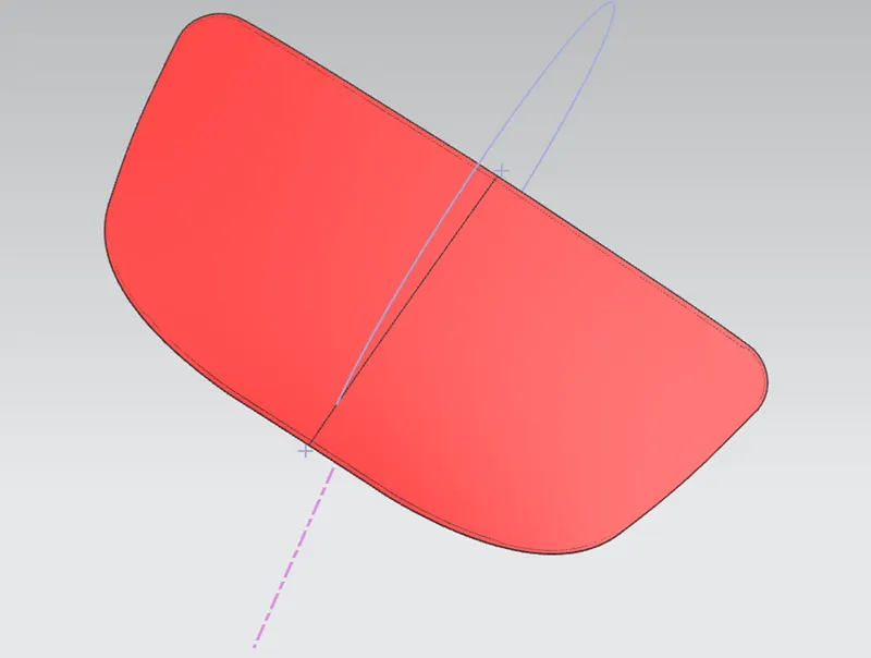
- Inner panel
This is reinforcement for the outer panel and this design is crucial in dissipating the force and also a major role in safety standards of the car
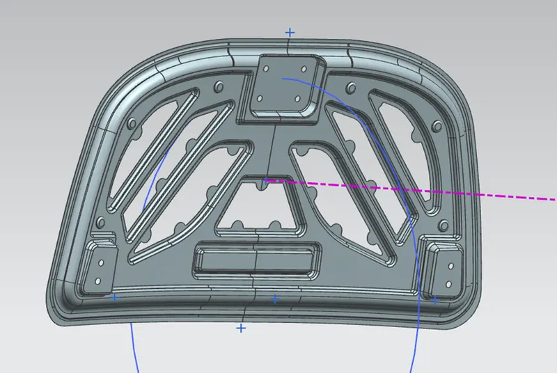
- striker and striker reinforcement
This is the part which seals the hood with the engine compartment and this is basically a lock for the hood and reinforcement is added to provide additional strength
Striker
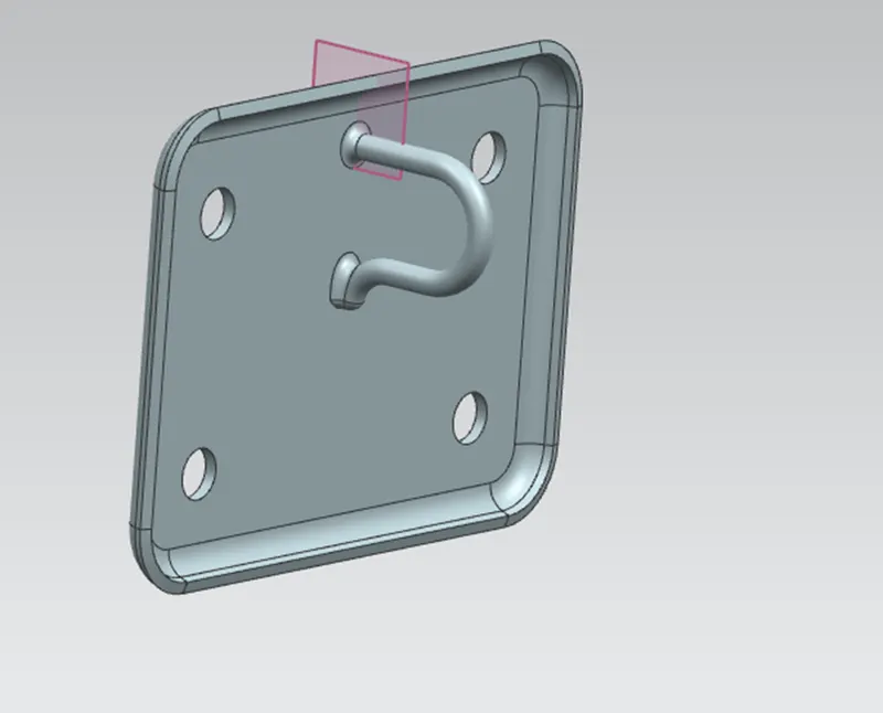
Striker reinforcement
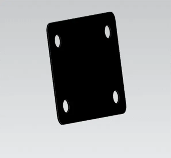
- Hing and hinge reinforcement
This enables the rotation motion of the hood about a axis and also has reinforcement for the same purpose
Hinge
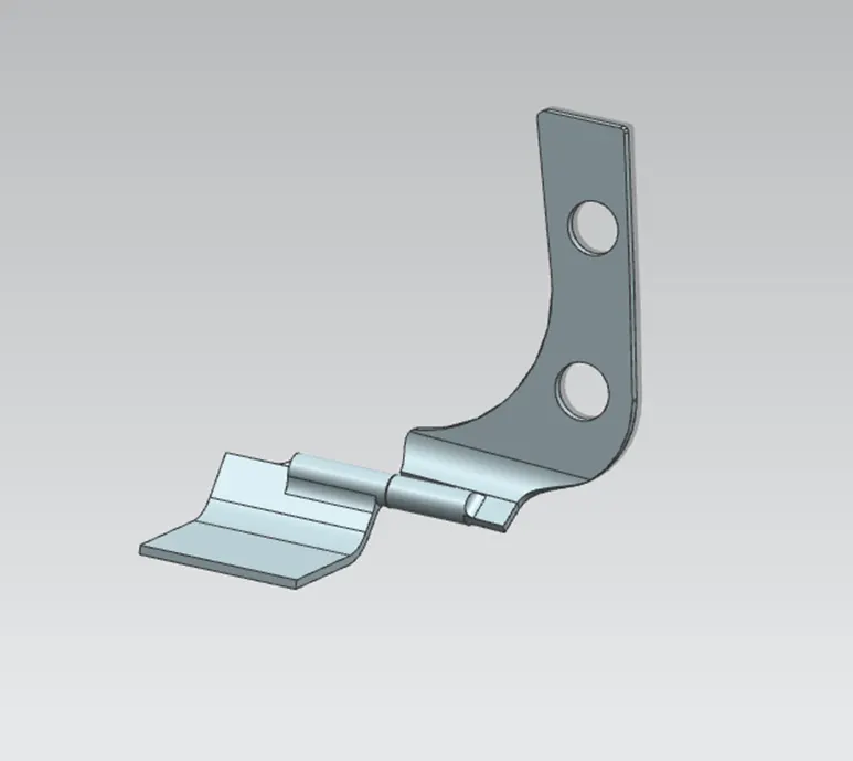
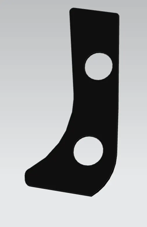
Hinge reinforcement
The various approaches to be followed to get the desired hood is given below
- Manufacturing approach
- NCAP approach
- NVH approach
- Ergonomic and serviceability approach
The manufacturing approach
The important criterion for manufacturing sheet metal is taken and design is made in accordance to the criteria and the various rules for the criteria is given below
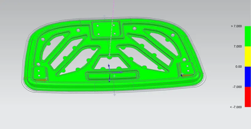
- The draft for the sheet metal should be minimum of 7deg
- The between adjacent edges should be between 6-8mm
- The fillet radius value should be minimum of 3mm + thickness of the sheet
- All edges should be smooth
NCAP approach
The NCAP approach is nothing the but the safety enhancement feature for the pedestrian as well as the passengers in the car the important criteria for this is
- The embossed should be created to dissipate the force towards the hinge and to complete hood
- Embossed also should create the soft areas for pedestrian safety
- The design should be made to reduce the head impact zone based on the side line criteria
- There should be a offset of 90mm from the engine impact zones for the inner panel
[Note
NCAP – NEW CAR ASSESMENT PROGRAM. this is done to analyse the car for various accident and give rating to the car based on the Impact intensity to the humans both the passenger and the pedestrians
Side line and impact zones
- The side line the first point of contact of a line drawn 45 deg from the floor and there are two types of hoods based on the side line they are
1.Inlaid hood
- Wrap around hood.
in the first model the side line is in the hood itself and in the second model the side line is in the rim of the car
- The impact zine is of three areas they are leg impact zone, pelvis region, adult head impact and child head impact zones
- The better the soft spots in the head impact zones the better will be the safety standards and rating from NCAP
- Adult head impact distance from front-1500mm
- Child head impact distance from front-2100mm]
NVH approach
- There should be less vibrations from the hood for the passengers of the car
- Covering of all areas of the hood from vibrations
- Providing cost effective mechanism in reducing vibration
Ergonomic and serviceability approach
- The design should be easy to use or is comfortable for the humans to use
- Proper height of hood opening depending on the region
- Proper finger gap for the region
- Then the position of the hinge and striker without affecting the other components position or their service requirements and proper positioning of support rod
the design process
the design approach followed here Is top-down approach i.e., the assembly is first created and the various parts are created with parametric modelling
- First the given input class A surface by styling engineer is imported and made as a base
- Then the class a Is fixed in the assembly then it is copies to the inner and outer panel parts using the wave geometry linker in the assembly work bench
The design process of various parts and the validation base on approach individually is given below
1.input
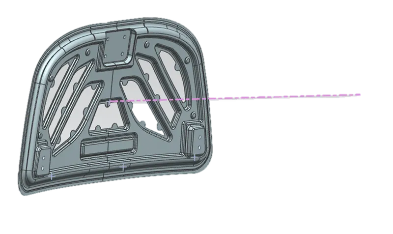
- First tooling axis is created using the draw direction and creating a line using edge points of the class a and making tooling axis in the drawing direction perpendicular to line created then it is imported to the inner and outer panel
1.the inner panel
- First the input surface is offset to 0.75+0.2+075 based on master section and hemming clearance
- Then it is trimmed using the yz plane
- Then based on master section the outer edge is offset and respective embossed are created with giving draft in tooling direction and edges are also blended as per the master section
- After creating the full master section development of the inner panel then additional features are created
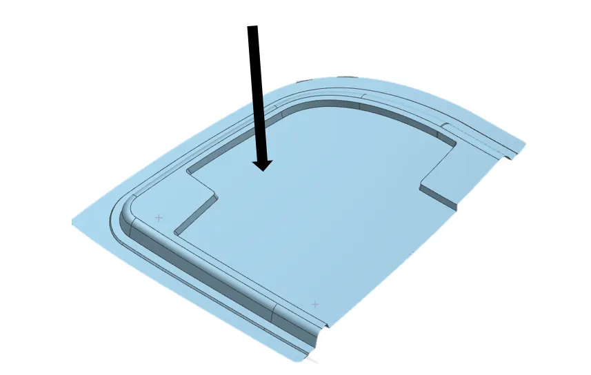
- Then embosses are created first with sketch excluding the striker and hinge assembly positions for about 9.5mm in directing inwards
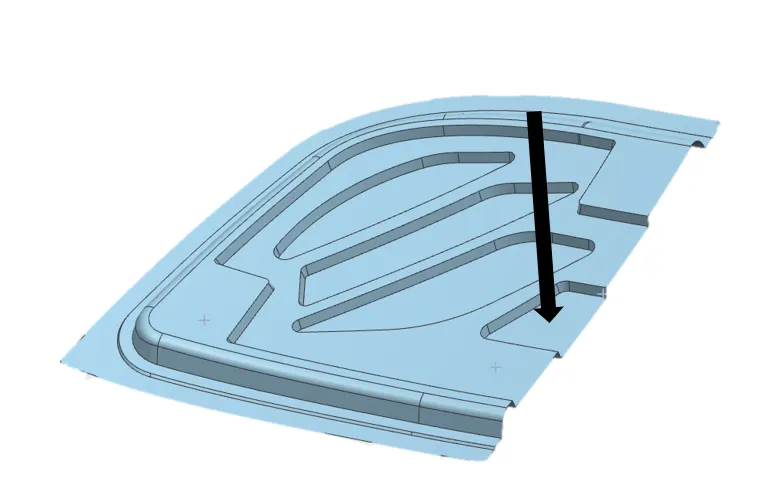
- Then final embossed for the force dissipation is created in an offset of another 9.5mm
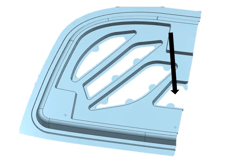
- Then to make soft spots materials are removed in the embossed faces and also mastic points are created using the rules for them
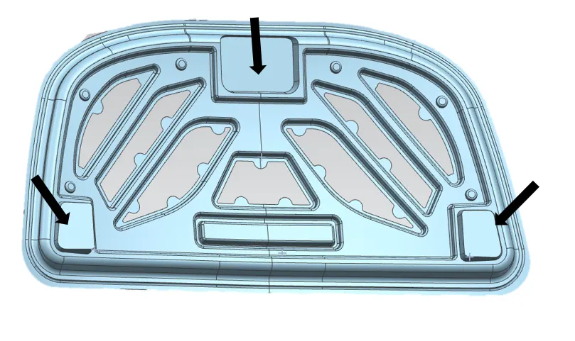
- Then the embossed for the hinge assembly and striker are created using the datum plane reference using geometry wave linker and assosiative embosses are made
Master section
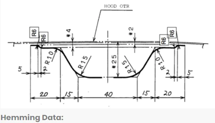
Master section conformation
First embossed surface
Final emboss
Embosses with material removed with mastic points
Final inner panel with hinge and striker embosses
The design validation of inner panel
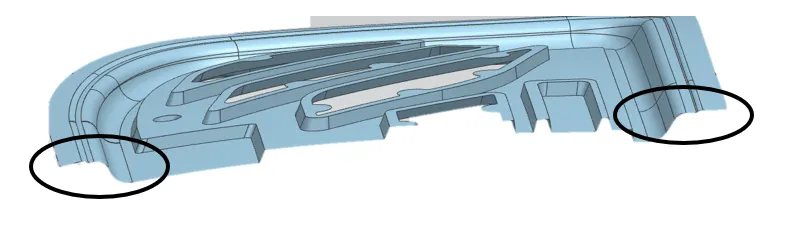
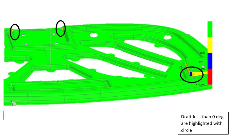
Manufacturing perspective - the design is made with min gap of 6 mm between edges and fillet value of 3+thickness is maintained in most areas and draft nominal value of 7 is maintained in maximum areas then sharp corners in the embosses are also made smooth
Tooling axis for draw direction and draft
Draft analysis
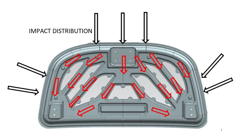
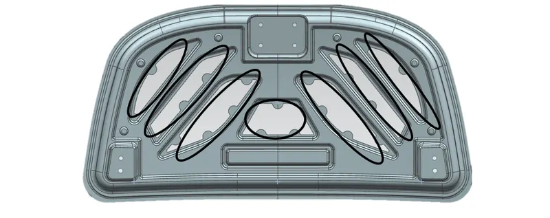
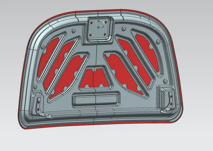
NCAP perspective - the design of the embosses are made in the way of dissipating the force towards the hinges and also with side impact towards the striker and the hinge and the soft spots have more area in the pelvis and head impact zone as in the head impact zone deformable stiffener part is there
IMPACT FLOW
HEAD IMPACT SOFT SPOTS
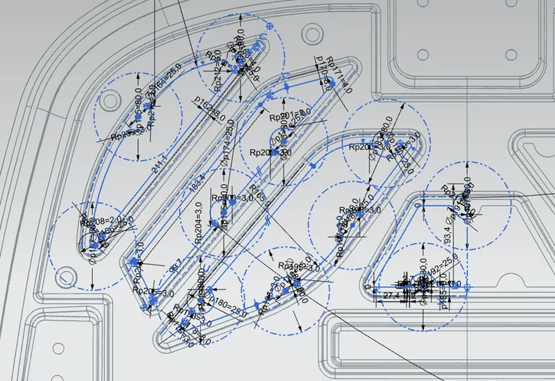
NVH perspective - the design has been made for NVH by using the mastic points and the each mastic has an area coverage of about 80mm and the points are designed in a cost effective way base on the coverage of the mastics and a stiffener part is also added to the inner panel which will serve the purpose of both head impact reduction and also in NVH coverage
MASTIC CREATION WITH ECONOMIC CRITERIA AND COVERAGE
STIFFNER PAD FOR LOWER REGION
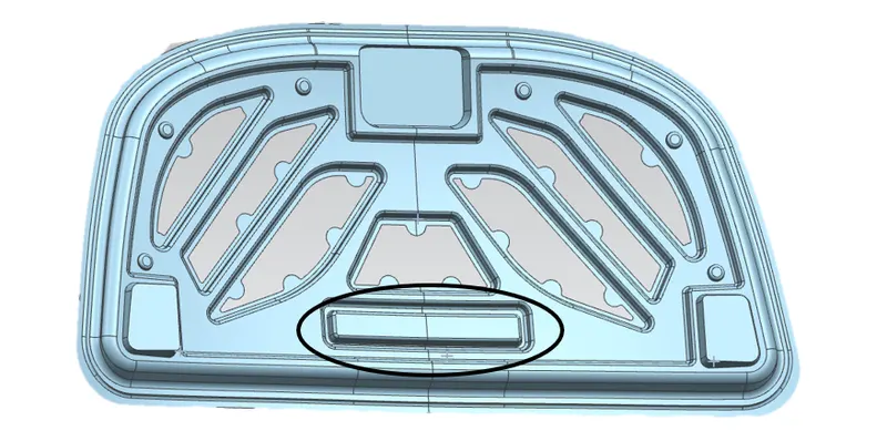
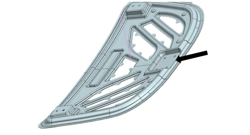
Ergonomic and serviceability - the ergonomic perspective is also utilised in the striker dent created inside so that the humans feel comfortable in releasing the secondary lock of the striker and also space on both sides are provided to
FINGER SPACE
The outer panel
- The outer panel does not have a specific engineer feature rather is to be appealing to the customers and should have good drag coefficient
- Then major criteria with the outer panel are the attachability to the inner panel with and major machining and that why hemming is done therefore the design validation does not have a major role and this panel is to be validated only on the hemming operation perspective
[Note
Hemming process -Hemming is a attachment operation performed mainly for areas where the appearance need not to be compromised and it is a process where the simply one part is wrapped around by another ]
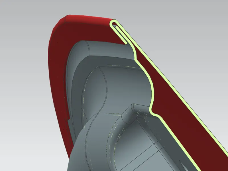
Hemming perspective- the hemming clearance of 0.2mm is given in both the ends and also the hem is made into the inner panel up to 4mm and relief is also given at the smooth edges at the hinge region to ensure the spring back (elastic limit capacity) ability of the sharp corners and it also given the required front relief
The hinge striker and their reinforcements don’t have much of validation so we go to the assembly of the parts of the hood
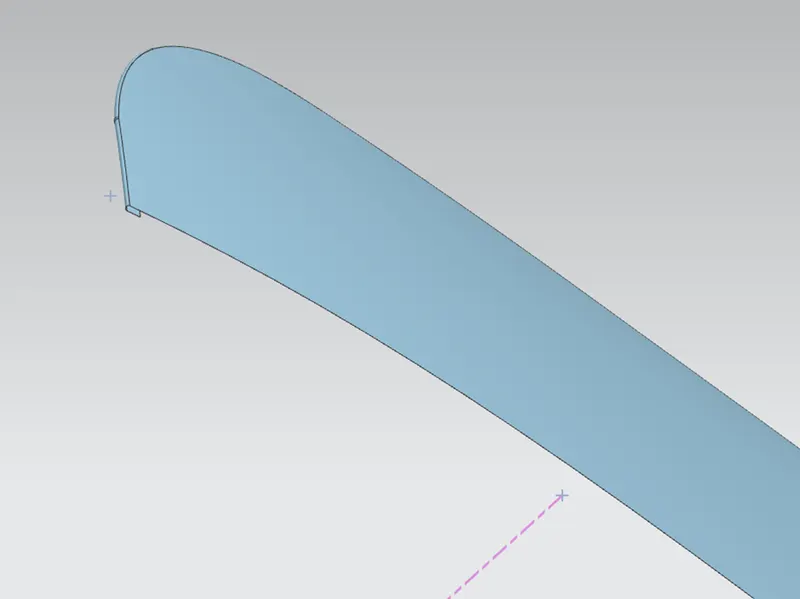
RELIEF IN SHAPR CORNERS
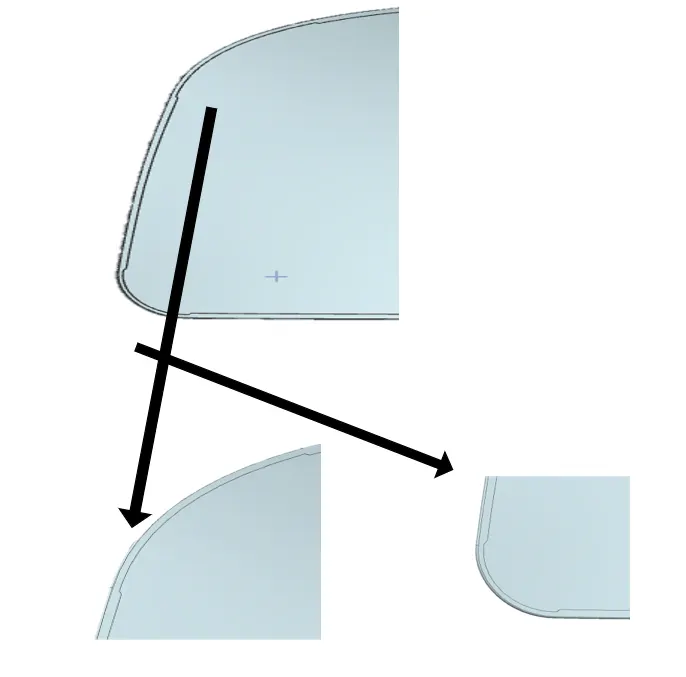
FRONT RELIEF
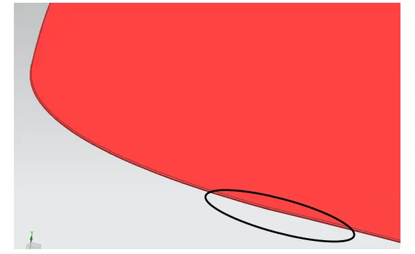
HEM CLEARANCE OF 0.2MM
Assembly
The assembly is nothing but to follow the 3-2-1 principle and fixing the 6deg of motion in a desired aspect to have proper control of the position of the part in the assembly
Hood assembly
- The input class A is first fixed in its position and the hood outer and inner panel are designed using it as a reference and doesn’t need any constrains
- The important criteria are with the position of the hinge and striker with respect to each other and specified rule for the positioning is also followed
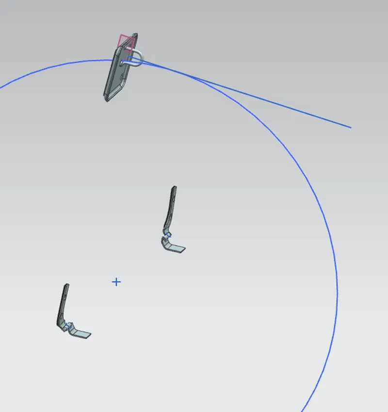
- The rule is that a circle drawn with the centre point between two hinge and a line of striker in its lock should be tangential to each other
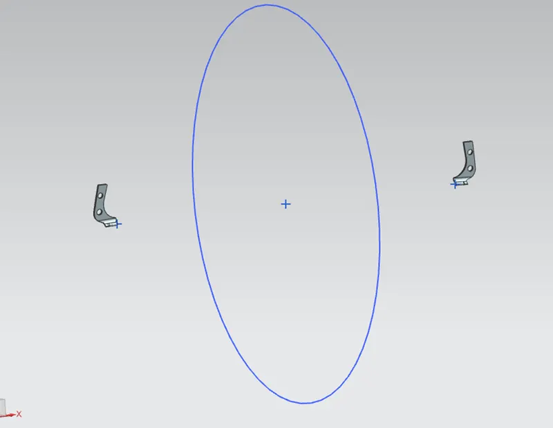
- At first the single hinge is positioned with making hinge centre line parallel to x axis and the engine part of hinge yz plane is made parallel with the yz of the assemble
- Then a distance constrain of 2mm is created and then new component of hinge
- Then hinge is them mirrored with associative and copied constrains
- reinforcement is created using the reference surface from the hinge assembly and is also made associative and doesn’t require and constrain and is also mirrored with the associative option
- then a point is created in between the hinges and a circle of about 700mm is created
- then the striker where first a mid plane of yz is made aligned with the mid plane of the yz of assembly
- then a line is drawn in horizontal from the yz plane of the striker from the centre point of the lock
- then the lines of the striker and the circle are made touch align
- then the striker is moved to the required ergonomic position then and reference surface is taken into the inner panel
- then this reference used to create the embossed plane and sketch for the striker placement in the inner panel
- then a distance alignment of 2mm is give and finally the striker reinforcement is created using the reference of the constrained striker
HINGE PLACEMENT AND CIRCLE CREATION
STRIKER PLACEMENT WITH THE CIRCLE AS REFERACE
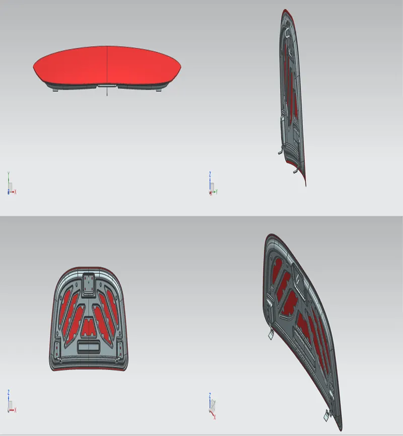
FINAL ASSEMBLY
conclusion
thus, the design of hood assembly considering various rules and approaches has been done and validated successfully