Week 10- Assembly Workbench
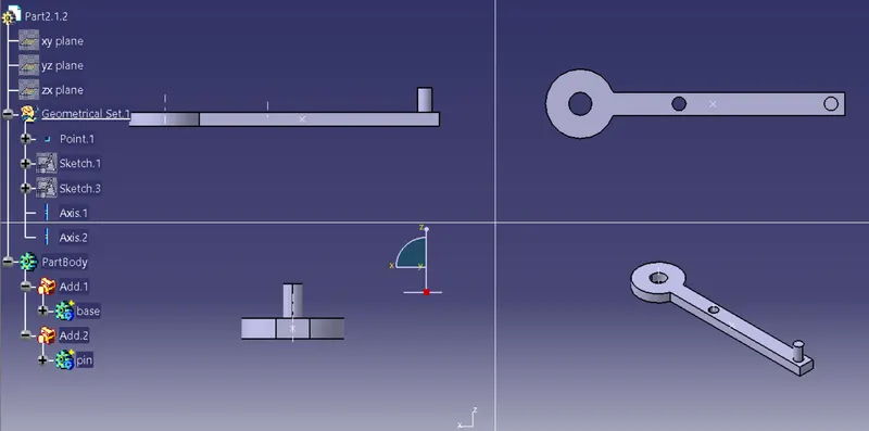
QUICK RETURN MECHANISM ASSEMBLY
INDIVIVUAL PARTS
1.FIXIN PIN
- then fixing pin is created using pad
- and boolean operation is used to create the part
- in assembly it acts as a fixing point
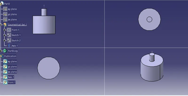
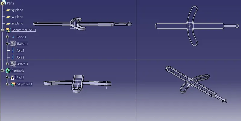
2. GUIDER
- this is created using sketch and pad\
- in assembly it act as a guider for the x and y direction pins
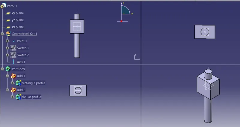
3.Y DIRECTIN PIN
- this is created using pad and boolean operation of add
- in the assembly it is used to move tranlation along the y axis of the guider
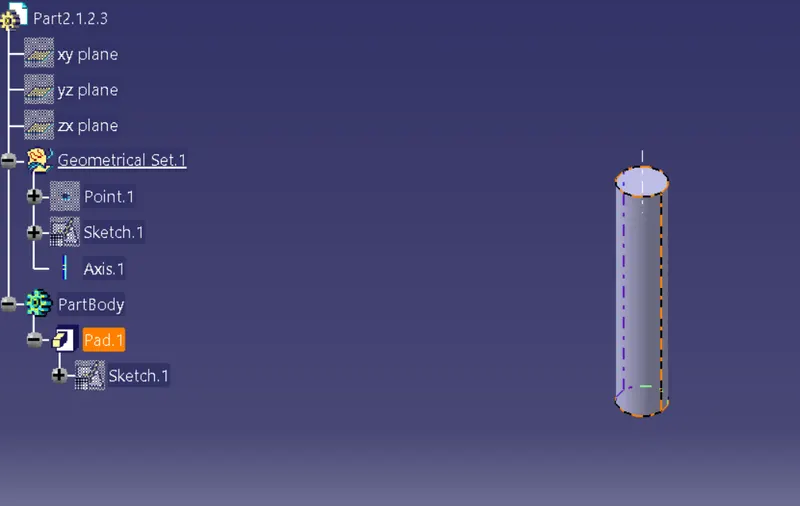
4. X DIRECETION PIN
- this is creatd using pad alone
- this is used in assembly to create translation along x direction
5. UPPER LOCK
- this is created using pad and boolean operation of add and remove
- this is used in the assembly to lock the two pin in their direction and to conver the reciprocating action into rotating motion
ASSSEMBLY
CONSTRINS
1. COINCIDENCE - this is used to make any points or axis or facaes to lie on the same plane or axis or point or same surface boundry
2.CONTACT CONSTRAIN - this constrain is used to create two surfaces or face to be in contact with movement and it faciiitates the movement along with the constrin and it make the motion free considering the constrain condition
3.OFFSET CONSTRAIN - this is used as a distance consrtrain between two parts based on surface or axis or point or edges
4.ANGLE CONSTRAIN - this is used to create angle between two parts
5.FIX - this is used to fix a component in its place and restricts motion
6.FIX TOGETHER - this is used to fix two components together within a particular place and it also restricts movement
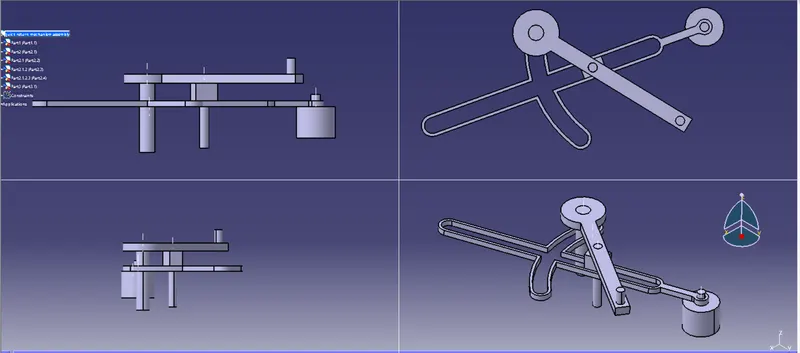
QUICK RETURN ASSEMBLY
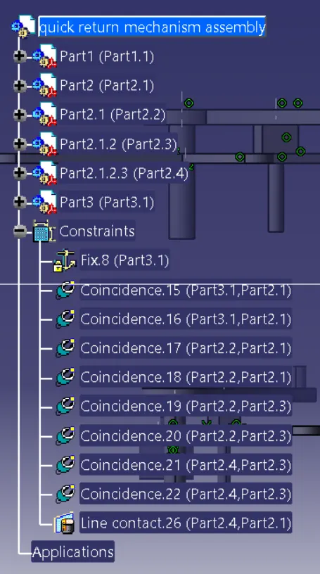
- here first the fixin pin is given fix constrain
- then guider hole axis and the fix pin axis is made coincident
- then contact face of the guider and the contact face of the fix pin are coincided
- then the y axis pin face is made coincident with the y axis slot of the guider
- then the lower face of the y axis pin is made coincident with the lower face of the guider
- then the top provision of the y axis pin axis is made coincident with the locker and also the contact faces are made coincident
- then the axis of the x axis pin and the locker axis are connected and the contact face are also coincided
- then finally the x axis pin and same axis face of the guider are made into contact constrain
- these constrains also ensures the movement of the assembly in the desited way
CONCLUSION
hence the required parts as per the dimensions given are created and the required assembly is also created in the simulatable way
CONSTANT VELOCITY JOINT ASSEMBLY
INDIVIDUAL PARTS
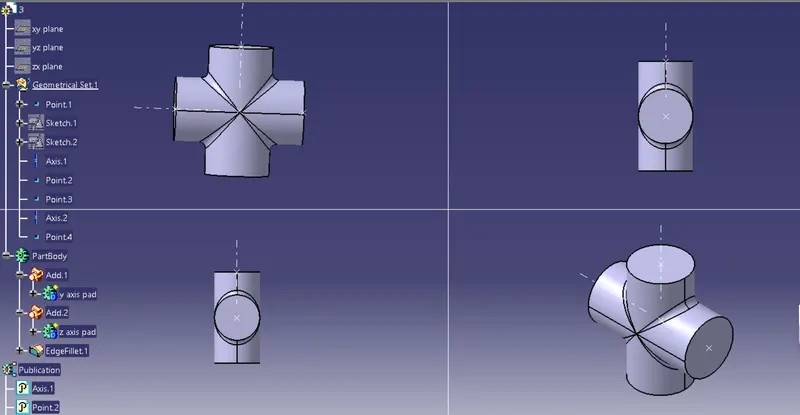
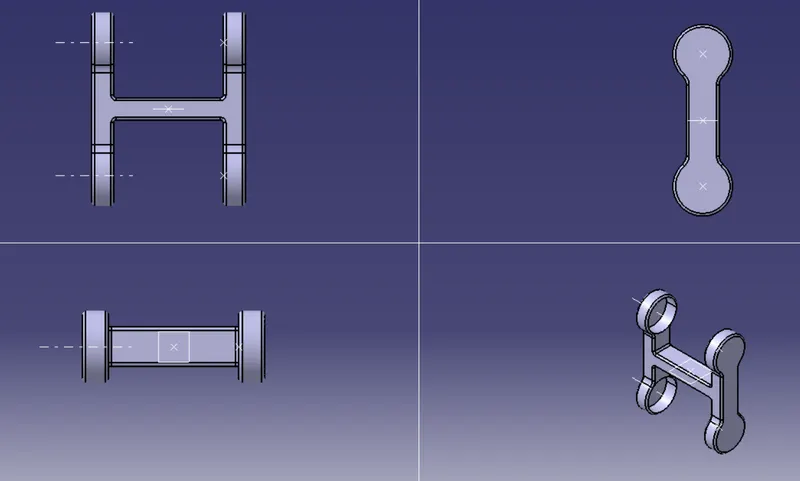
1.SPIDER
- this is created using two sketches and then padded and then they are added to each other using the boolean operatin add
- in assembly is used to give freedom of movement of rotaion along x axis for yoke and y axis for the master center yoke
2.SIDE YOKE
- this is created using two sketches and are padded and also two sketches to pad component to remove and this are performed using the boolean operation of add and remove
- this is used in the assembly for connecting the transmission and driving ends
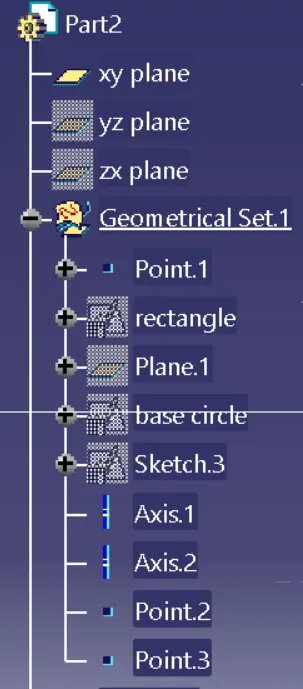
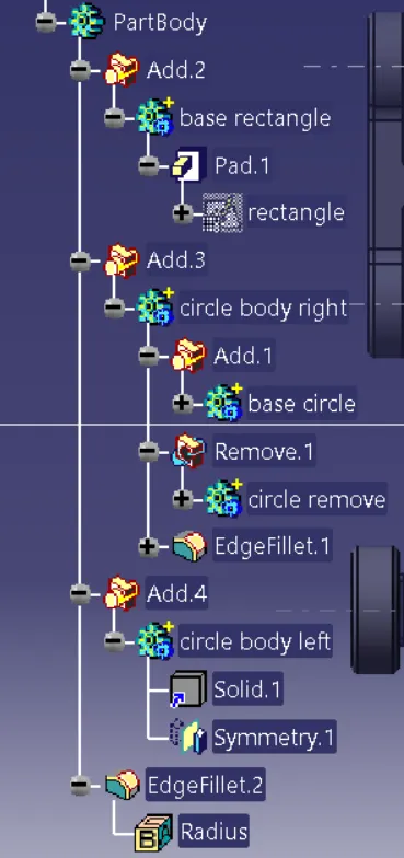
3. MASTER CENTER YOKE
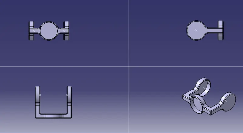
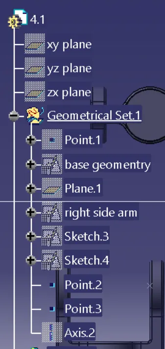
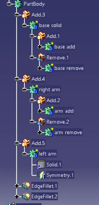
- this is created using the two sketches and pad them and also seperate sketch is made for removing material and it is also paded and then using the boolean operation of add and remove part is made
- this is used in assembly to act as a join for two spider and it also rotates along the z axis
ASSEMBLY
1. COINCIDENCE - this is used to make any points or axis or facaes to lie on the same plane or axis or point or same surface boundry
2.CONTACT CONSTRAIN - this constrain is used to create two surfaces or face to be in contact with movement and it faciiitates the movement along with the constrin and it make the motion free considering the constrain condition
3.OFFSET CONSTRAIN - this is used as a distance consrtrain between two parts based on surface or axis or point or edges
4.ANGLE CONSTRAIN - this is used to create angle between two parts
5.FIX - this is used to fix a component in its place and restricts motion
6.FIX TOGETHER - this is used to fix two components together within a particular place and it also restricts movement
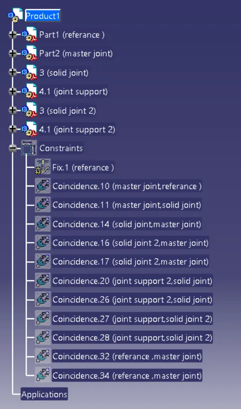
CONSTANT VELOCITY JOINT ASSEMBLY
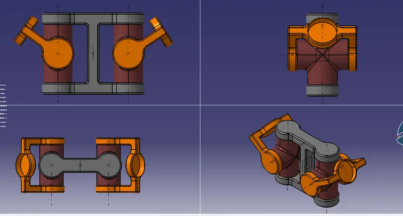
- first the referance part is created as a referance
- the first master center yoke center point is made coincident with the referance point
- then center yoke zx plane and the referance part zx are made coincident
- then the axis line of center yoke and the axis of spider are made coincident and also the faces are made coincident same is done for other side spider
- then yoke axis and spider axis are made coincident and their zx planes are also made coincident
CONCLUSION
thus the individual pars and assembly of the contant velocity joint is created as per the requirement