Roof Design
DESIGN OF CAR ROOF WITH REINFORCEMENTS USING NXCAD
Introduction
the roof is the top cover of a car it has significance in various perspective of a car and they are in performance and efficiancy of a car as it affects the air resistance and it also plays a importance in satfety ratings of car as it the region getting impactacted during roll over test and therefore it is critical in choosing the materials and placing and number of reinforcements as only the flat surfaces will be sort of strength than curved regions and there is also reinforcement placing formula .Snow load criteria as in foreign markets as it has to with stand snow and here we will see the various perpective used in my hood design and my hood design matching the master sections based on vehicle requirements
hood consideration
- hood strength
- material selection and properties
- num of reinforcement and their positions
- assembly consideration
- consideration for vehicle to meet the ergonomic consideration
hood strength :
since hood should withstand the roll over test to meet the safety requirements it is nominal for the roof to have strength to weight ratio of 4:1
here weight implies the weight of the car
material selection:
the material selected is steel ASTM A 36 and is of thickness 0.75mm and is cold rolled sheet
properties:
- Ultimate tensile stress = 400-550 Mpa
- yield strength = 250 Mpa
- Youngs modulus = 200 Gpa
- Poissond ratio = 0.26
number of reinforcements and their positions:
- here i have considered the roof having both variants of standard and with sunroof and because seperate design for sunroof is costly i have made statergy of common reinforcements for both the variants
here we have five reinforcements they are :
- front roof rail
- center roof rail
- Bow roof 1
- Bow roof 2
- rear roof rail
for commonising the desing i have spot welded the center and bow roof 1
Assembly consideration:
the various parts of the roof are assembled together by the following method
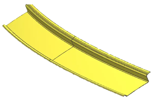
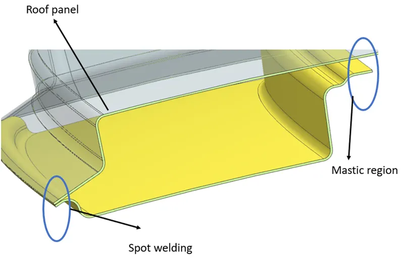
- front roof rail - it is spot welded to the roof at front side in x direction and is joined using mastic at the rear posion in x direciton
front roof rail
section view
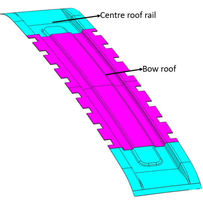
- center roof rail - it is joined to side flange of the roof in y direction through spot welding in the roof area Bow roof will be spot wlded to the center roof rail
- Bow roof 1 - it is joined to the center roof rail alone and not to the side flanges in y direction of the roof panel and it is joined to the center roof by spot welding and to the roof panel by mastic
center roof with bow roof
section view
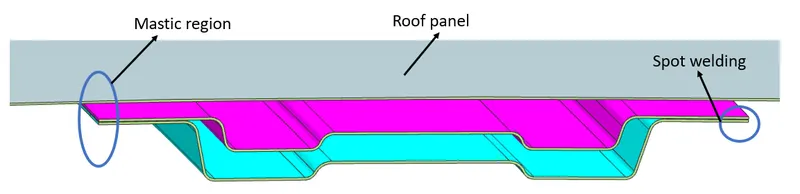
joining at the y flange of roof panel
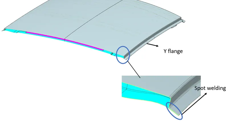
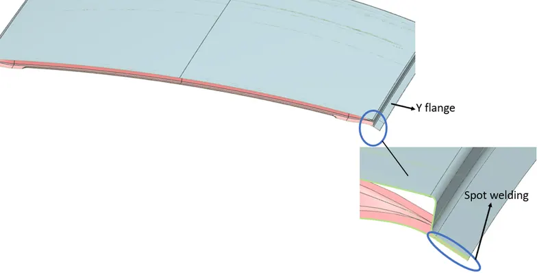
- Bow roof 2 - it is joined to the roof pane area through mastic and to the Y flange of the roof through spot welding
Bow roof 2
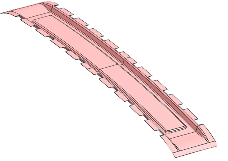
section view
in y direction
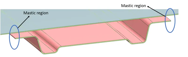
in x direction
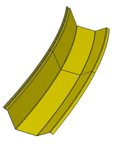
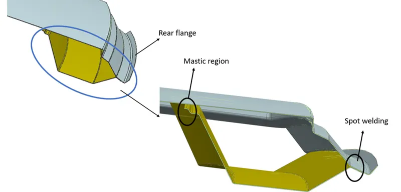
- Rear roof rail - the rear roof rail is attached to rear flange by spot welding and to the rear roof fange by mastic
rear roof rail
section view
ergonomic consideration
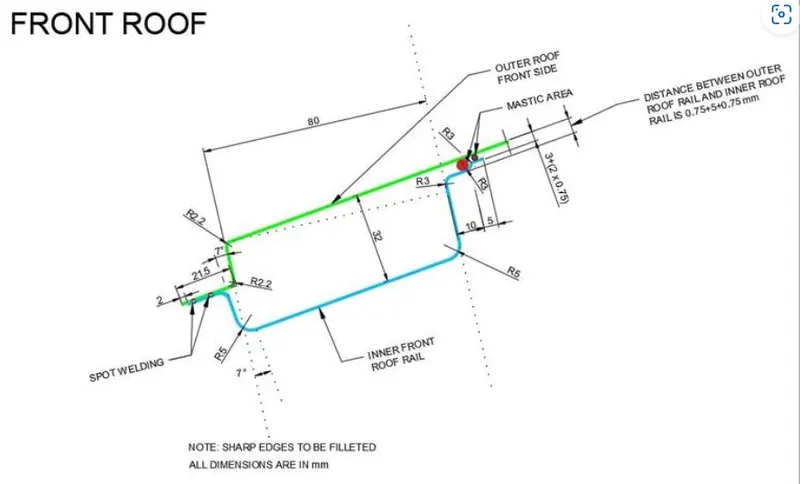
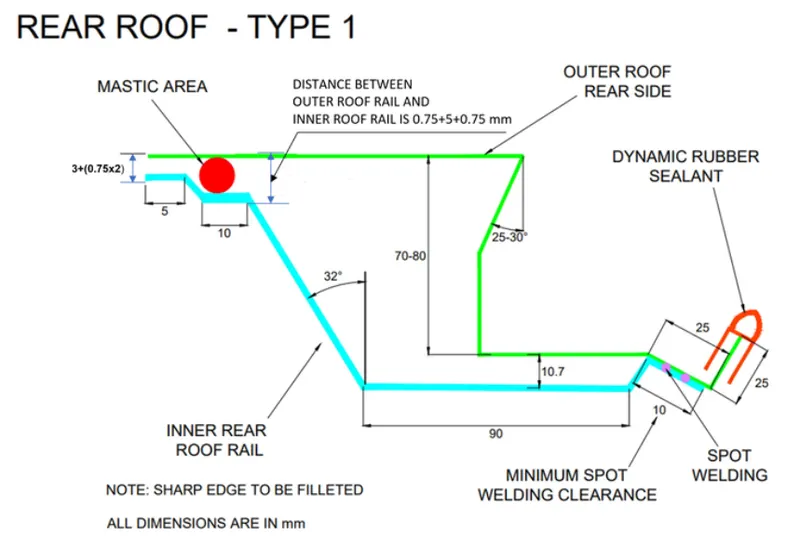
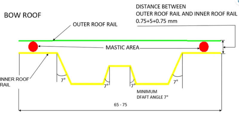
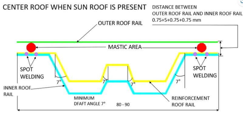
the ergonomic consideration taken here are actually the driver visibility criteria for the the rear as well as the front side of the car and the master section of the reinforcements are prepared based on these criteria the master section are shown below
conformity of design meeting the required standards
the following standards to be meet by the design to pass the verification
- DFM (design for manufacturing)
- master section and DFA(design for assembly)
- roll over requirement
- reinforcement placement confirmation
- snow load criteria
- rectification for not good in snow load
DFM
this is the manufactruring confirmaity for a sheet metal component the rules for dfm of a sheet metal are given below
- min draft of 7deg along drawing direction
- min flange lenth for tool holding and sheet metal free from cracks due to bending is 3*thickness of the metal i.e 2.25
1.FRONT ROOF RAIL
- draft
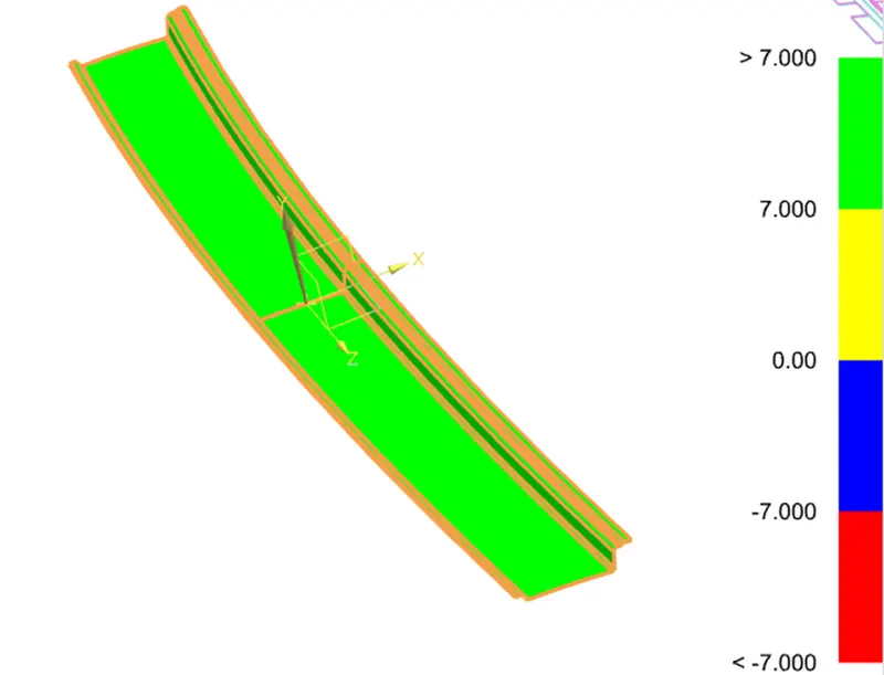
draft is conforming DFM
- flange length
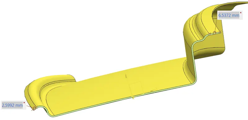
therfor the flange lenth is conforming for DFM
2.REAR ROOF RAIL
- DRAFT
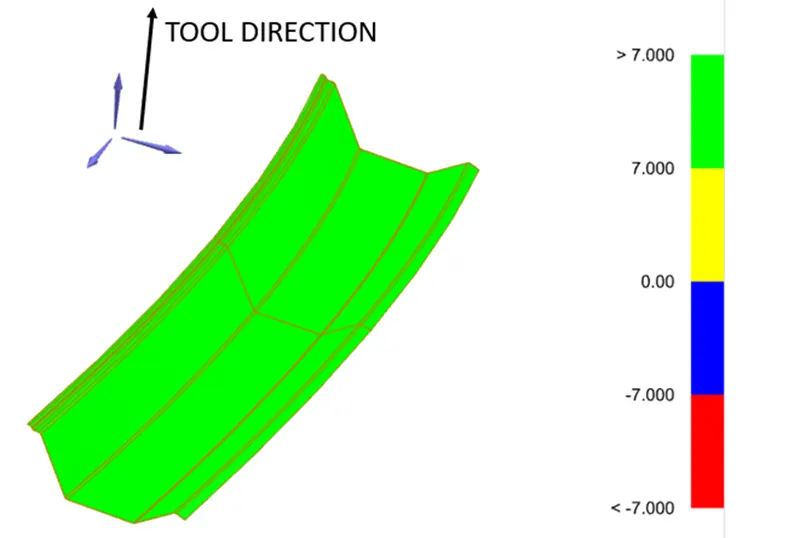
therefore draft is conforming DFM
- flange length
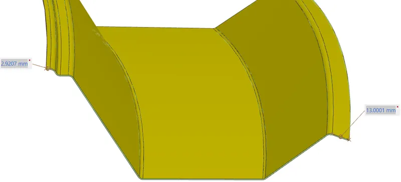
flange length is conforming
3.center roof rail
- Draft
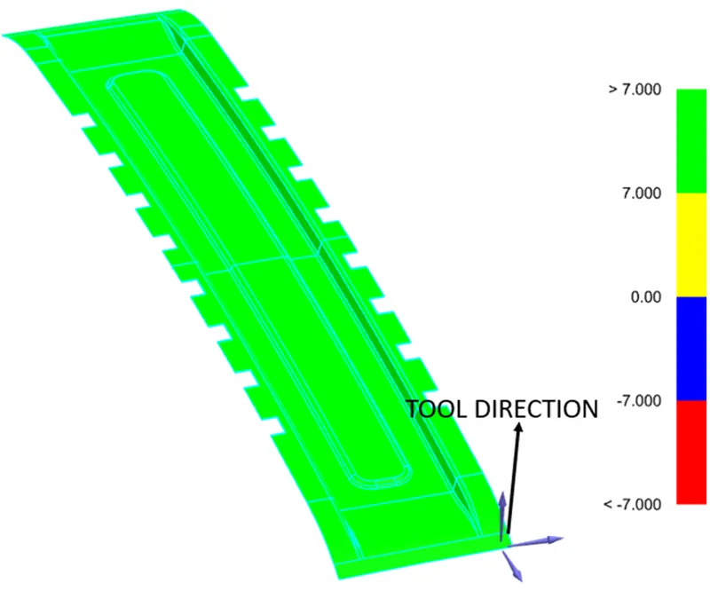
Draft is confirming
- flange length
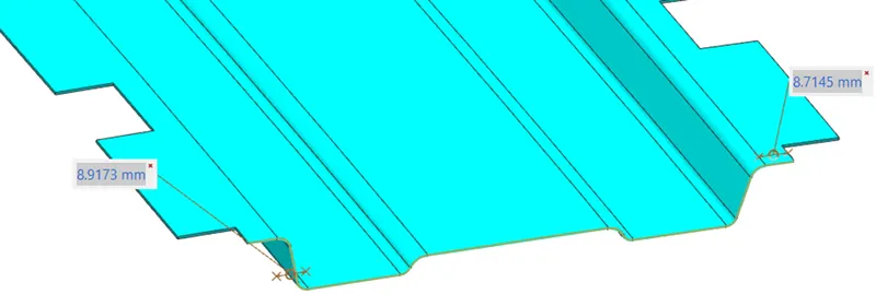
flange length is conforming
4.BOW ROOF
- DRAFT
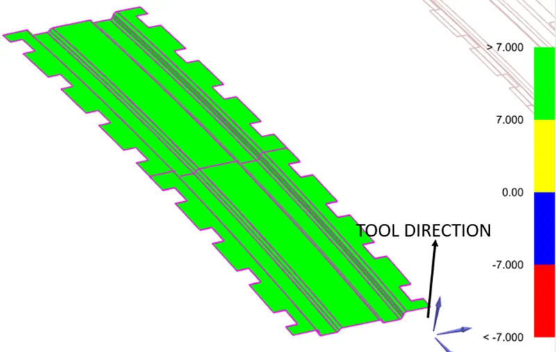
Draft is conforming
- flange length
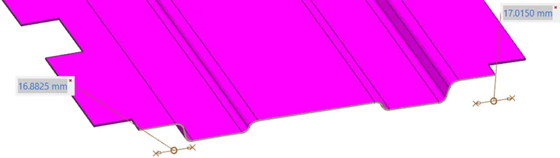
Flange lenth is conforming
4.BOW ROOF 2
- Draft
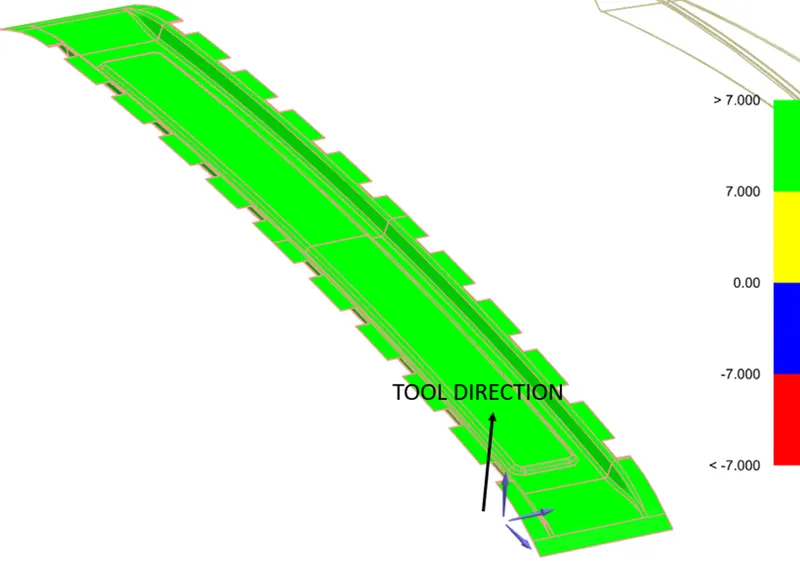
Draft is conforming
- Flange length
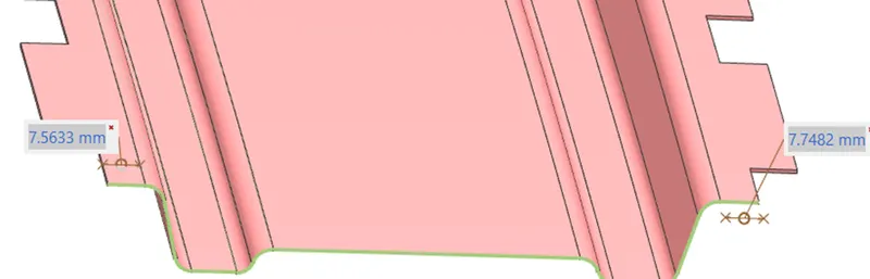
flange lenth is conforming
Master section and DFA
here we will see the master section confirmation and DFA confirmation
1.FRONT ROOF RAIL
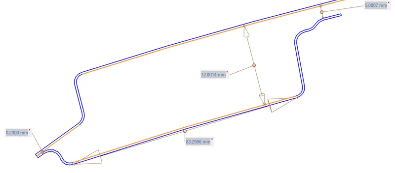
This is conforming the master section as shown above and the dimension 0.2mm in the front and 0.5mm in the rear also confirm to DFA where at front this is spot welded and at the rear it is joined by mastic
2.rear roof rail
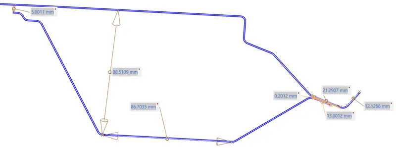
This is conforming the master section as shown above and the dimension 0.2mm in the front and 0.5mm in the rear also confirm to DFA where at front this is spot welded and at the rear it is joined by mastic
3.center roof rail and bow roof
master section
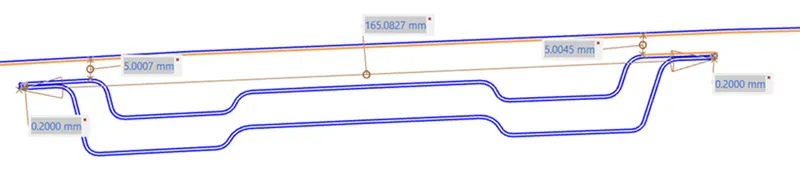
this is conforming the master section and 0.2mm between the center roof and bow roof conforming spot welding and the 0.5mm between the roof panel and center with bow roof conforming the mastic region
4.Bow roof 2
master section

this confirms the master section and 0.5mm clearance in the front and back confirm mastic region
Roll over requirement
as described in the beginning to meet the roll over requirement the roof should have strength to weight ratio of 4:1
we know that from material section
- ultimate tensile strength = 400-550 Mpa
let us take the minimum value of 400 Mpa
400 Mpa = 400 N/mm2 =
- the total arear of the hood from nx cad given below
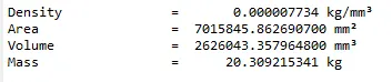
max load = ultimate tensile strength x total area of the roof
= 400*7015845
weight = 2040 kg (I have taken mahindra xuv 700)
= 2040*10
= 20400
max load /weight = 400*7015845/20400
= 14*10^4
our roof will withstand a 14*10^4 times the weight of the car
To earn a good rating, the roof must withstand a force of 4 times the vehicle’s weight before reaching 5 inches of crush.
with the available load taking ability our roof wil withstand the load and will pass the safety test
Reinforcement placement confirmation
The reinforcement in the sense is nothing but all the additional roof rail placed other than the front and rear roof rail i.e the center roof with bow roof section and the bow roof 2 section
to predict weather the placement of the reinfocements are right or wrong we use the below formula also known as heat distortion formula
to say about the approach that i have used to place before confirming the position is by the simple concept where the curved section of the roof have more strength than the flat faces and so i have placed the reinforcements in the flat regions of the roof
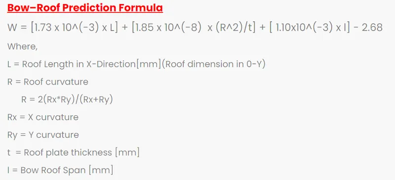
the datas for the calcultaion from my roof are given below with referance images
1.roof length- L
Here we will take the lenth of the roof along the x direction where we have taken the extreme edges excluding the ditch areas

therefore L = 2033mm
2.Roof curcvature R
first create points to create points for arc using sketch as shown below
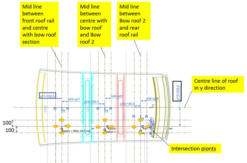
then these pints are projected and arcs are crearted and radius for these arc are measure and is used for calculation
Projected points with arc created
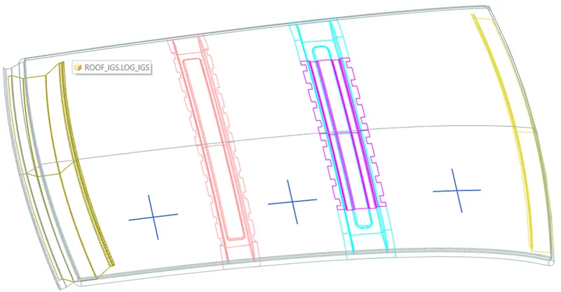
arc measurements

from above image we infer the following values
| S.NO | RX | RY | R |
| 1 | 5654.19 | 3335.13 | 419.4 |
| 2 | 4331.08 | 8871.31 | 582 |
| 3 | 3408.58 | 13761.2 | 546 |
3.Bow roof span I
it is the distance between adjacent reinforcements
the values from design is given below
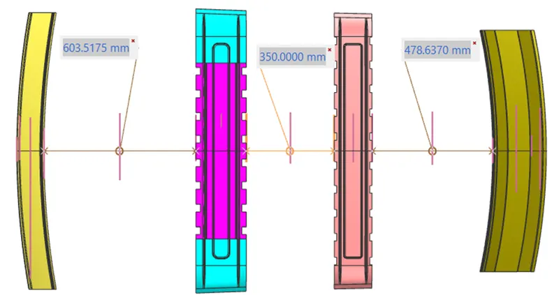
where
I1 = 603.52
I2 = 350
I3 = 478.64
the bow roof prediction calculation is shown below
| S.NO | REGION | R | I | LY | T(mm) | R^2/T | W |
| 1 | BT FR AND CR+BOW1 | 419.4 | 603.52 | 2033 | 0.75 | 23.4x10^4 | 1.5043 |
| 2 | BT CR+BOW 1 AND BOW 2 | 582 | 350 | 2033 | 0.75 | 45.16x10^4 | 1.2303 |
| 3 | BT BOW 2 AND RR | 546 | 478.64 | 2033 | 0.75 | 39.74x10^4 | 1.437 |
BT - between
FR - Front roof rail
CR - center roof rail
RR - Rear roof rail
therefore to pass the calculation the value of w should be as follows
w<2.7
therefore my design pass the calculation
SNOW LOAD CALCULATION
The snow load criteria is especially for the european and cold places where the snow will occour and because of which snow will be accomodated on the roof of the car and so calculations are made to confirm the ability of the roof to with stand the snow weight without being deformed
the calculaiton forumula for snow load is given below

where
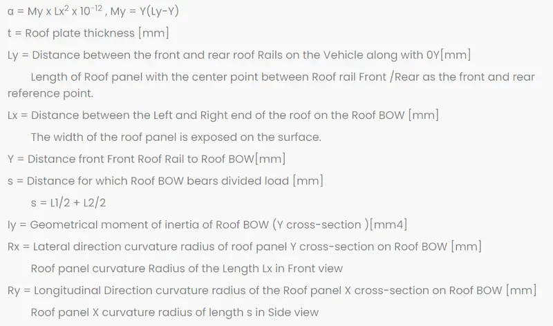
the datas for the snow load calculation are given below in the following
1.the moment of inertia Iy
since in the center roof rail and the bow roof 1 are spot welded together they are considered single section and inertia of each section is calculated and added together
- center and bow roof 1
the referance image of center roof rail is first given below
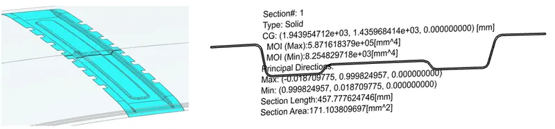
here Iy1 = 8.25X10^3 mm^4
the referance image for bow roof 1 is given as follows
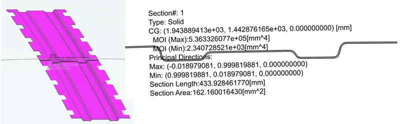
here Iy2 = 2.34x10^3mm^4
therefore the total Iy = Iy1+Iy2
Iy = 10.59x10^3mm^4
- center with bow roof rail 1 and bow roof rail 2
in the similar way Iy for this section is given below
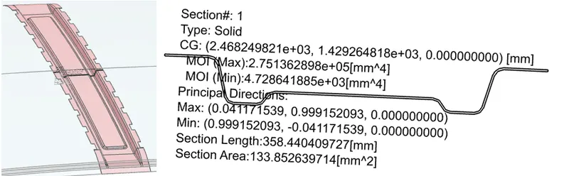
Iy = 4.72 x 10^3mm^4
2. Lx
- for the three section the value of Lx from my design is given below with ref image
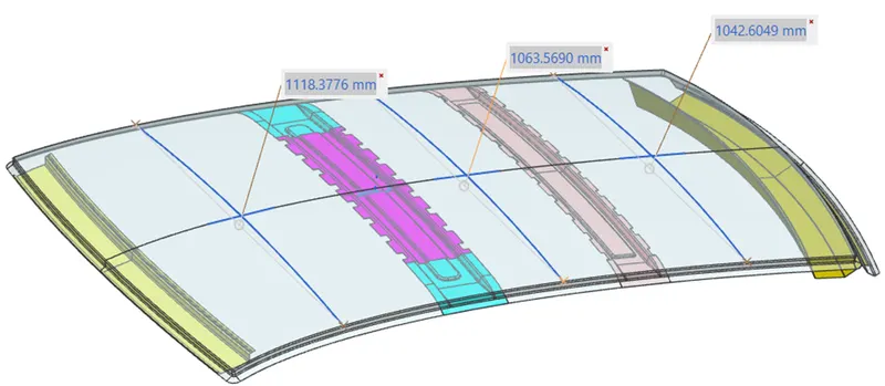
Lx1 = 1118.37
Lx2 = 1063.6
Lx3 = 1042.6
3. Ly
Here we will take the lenth of the roof along the x direction where we have taken the extreme edges excluding the ditch areas
therefore Ly= 2033mm
4.center to center distance of adj sections - Y
the center to center distance of the three sections is given below
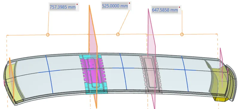
y1 = 757.39mm
y2 = 525mm
y3 = 647.6mm
5.Distance in which bow roof bears divided load S
this can be calculated using the y value calculated above
s1 = y1/2 + y2/2
= 757.39/2 + 525/2
= 64.19mm
s2 = y2/2 + y3/2
= 586.29mm
s3 = y3/2
= 323.8mm
6. local radius Rx and Ry are calculated as follows
first sketch for points are made as shown below
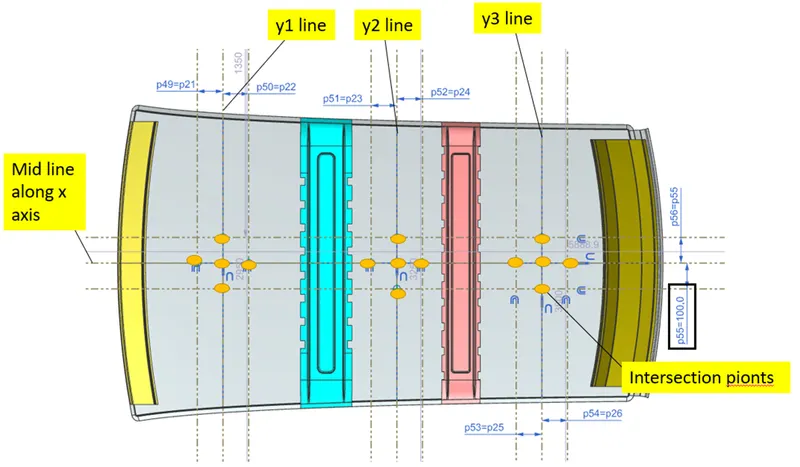
then the points are projected into the roof and arcs are made connecting the points as shown below and their local radius measured which is the Rx and Ry value
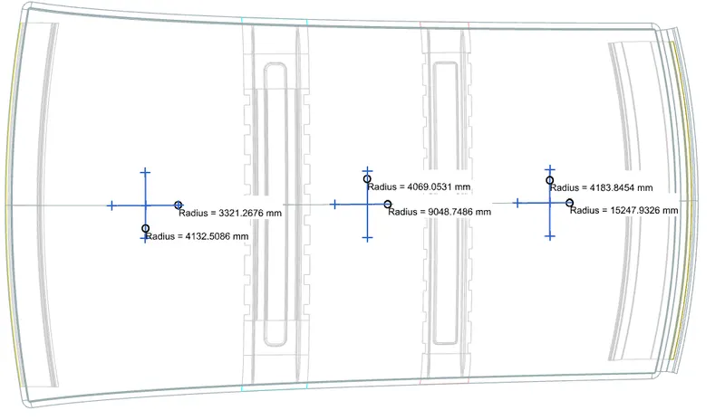
| S.NO | REGION | RX | RY |
| 1 | BT FR AND CR+BOW1 | 4132.5 | 3321.26 |
| 2 | BT CR+BOW 1 AND BOW 2 | 4069 | 9048.74 |
| 3 | BT BOW 2 AND RR | 4183.84 | 15248 |
BT - between
FR - Front roof rail
CR - center roof rail
RR - Rear roof rail
7. My
My = y (LY - Y)
we can calculate as the values for this calcultion are available above
hence we have all the datas to proceed with the final calculation which is given below
FINAL CALCULATION
| REGION | Iy | α | Lx | Ly | Y | S | Rx | Ry | T | Qr | GOOD (G)/ NOT GOOD(NG) |
| BT FR AND CR+BOW1 | 10.59x10^3 | 0.0134 | 1118.37 | 2033 | 757.39 | 641.19 | 4132.5 | 3321.26 | 0.75 | 20635.73 | G |
| BT CR+BOW 1 AND BOW 2 | 4.72 x 10^3 | 0.9 | 1063.6 | 2033 | 525 | 586.29 | 4069 | 9048.74 | 0.75 | 6.8135 | G |
| BT BOW 2 AND RR | 1 | 1042.6 | 2033 | 647.6 | 323.8 | 4183.84 | 15248 | 0.75 | _ | _ |
BT - between
FR - Front roof rail
CR - center roof rail
RR - Rear roof rail
From the above calculation the judgement criteria is
Qr ≥ 3.1
therefore my design is confirming to the above criteria
RECTIFICATION FOR NOT GOOD IN SNOW LOAD CRITERIA
In case we are getting NG in snow load calculation we can infer from the calculation it is majorly depend on the inertia , local radius (Rx, Ry) and thickness of the material we can try and find out the possible and cost effective way to solve the problem
the solutions to the problems can be of the following
- modify the local radius by approaching the syling team
- in case styling is freezed then we can create local embossed on the roof surfaces and it will increase the radius locally and improve strength
- to increase inertia we can increate the area of the reinforcements by increasing length or by increasing the thickness of the reinforcements
here i have taken a case of creating local embossed to show a solution similarly other solutions can also be done using the value calculation and design modification to match the values
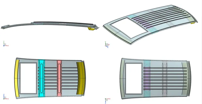
roof with local embossed
embosses are also created to commonise the roof variant with sunroof and without sunroof
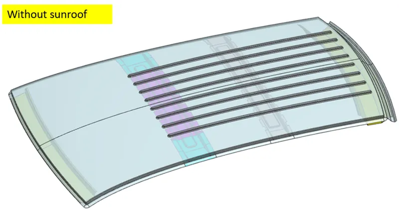
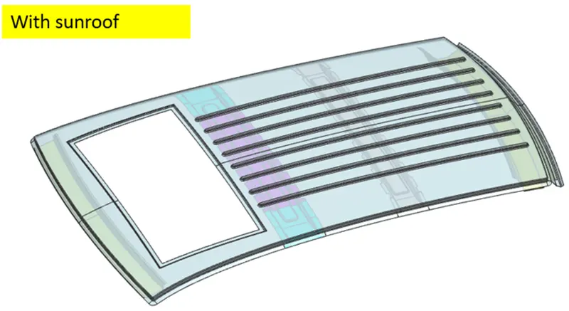
FINAL ROOF VIEWS WITH EMBOSSES AND SUNROOF
Conclusion
Hence i have designed the roof consiring various criteria from manufacturability to assembly , safety and visibiliity criteria and have also verified my design by above methods and calculations and my roof passed all the requirements