Week 8 - Challenge 2 - Base Bracket Design
CREATION OF SURFACE BODY OF BASE BRACKET AND TOOLING AXIS AND DFAFT ANALYSIS
TOOLING AXIS PURPOSE:
- The purpose of tooling axis is to first assign the direction of opening and closing of core and cavity
- The another purpose of the tooling axis creation is to ensure the clearance of the class c suface by the core and cavity
TOOLING AXIS CREATION
The tooling axis for the base bracket is created by the following steps
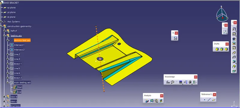
- first a point for the tooling axis is created and a dummy tooling axis is created and here the tooing is taken along the z axis
- then a axis system is created and intersection of the class a with referace to the axis system is created
X AXIS
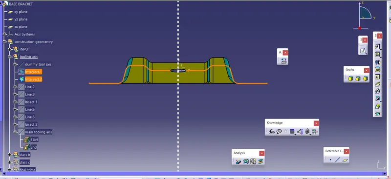
the intersection of the class a with respect to x axis direction in created and here we can see there are no parallel faces with respect to tooling axis and hence no action is requred
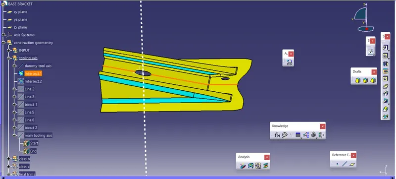
Y AXIS
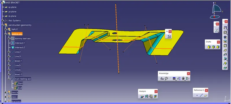
here the intersection is created and we can see two pairs of parallel faces are seen
- first pair lines are created using the points
- then the lines are bisected using the referace point and two lines
- then the same procedure is repeated for second pair
- at last the two bisected lines are bisected to create the tooling axis
DRAFT OF CLASS A
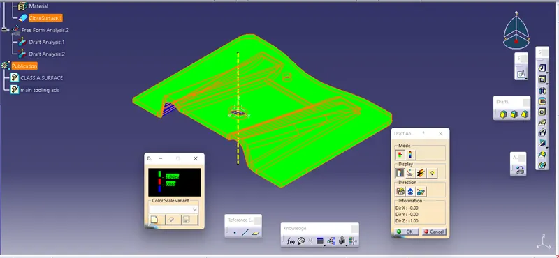
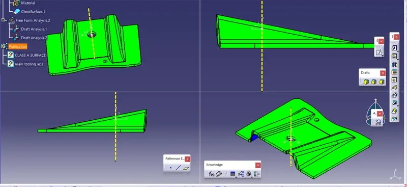
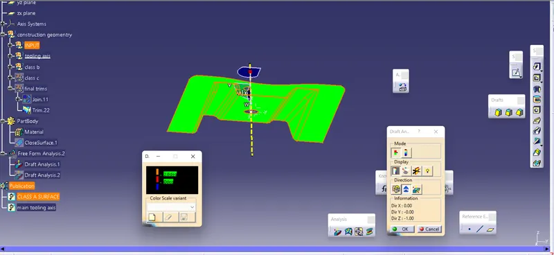
- now the draft analysis of the class a is created using the main tooling axis and the draft is properly ensured
- this is done as a preventive step to get proper final draft
CREATION OF CLASS B:
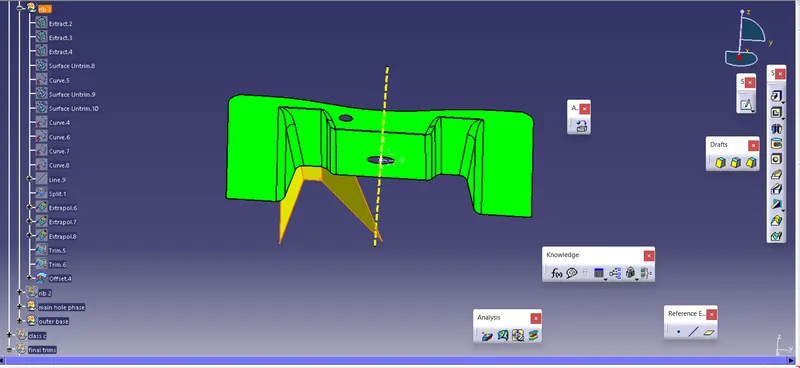
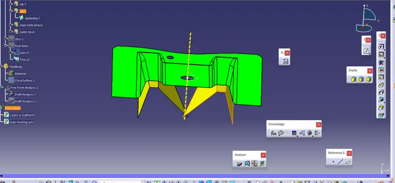
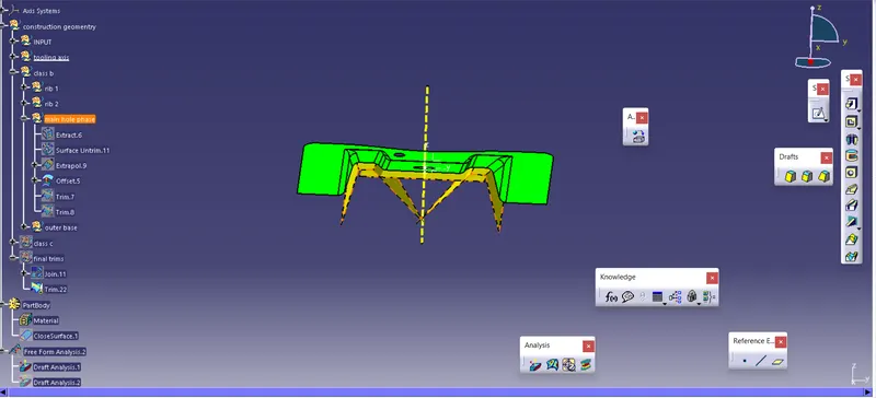
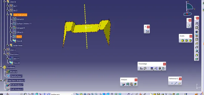
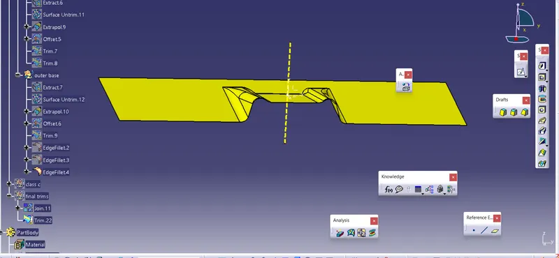
- first rib is created by extracting and extrapolated and then is trimmed and offsete to 2.5mm
- since both the ribs are symmentric the other is created symmentry
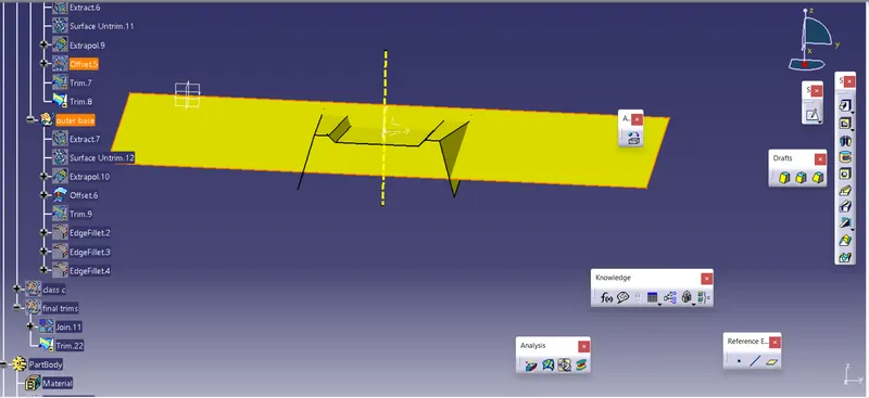
- then main holel phase is extracted and offseted to 2.5mm and untrimmed then it is trimmed to the two ribs
- then the outer phase is extracted untrimmed and offserted and trimmed to created class b surface
CREATION OF CLASS C:
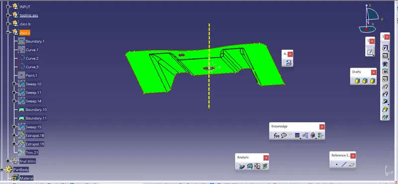
- the class c is created in three sub sets
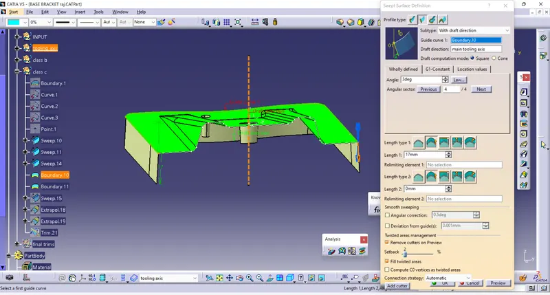
- first the boundry of the class a is created and is disassembled into three parts as main hole and small hole and outer boundry
- then the main hole is sweeped using the tooling axis and draft direction of 3 deg is given
- same followed for the small hole
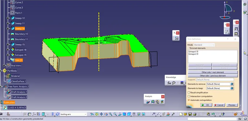
- then the outer boundry is seperated into two boundry and sweeped and then trimmed
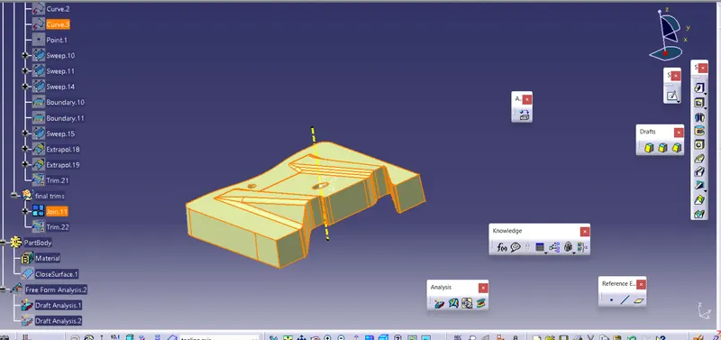
CREATION OF SURAFACE BODY:
- now the class a and class c are joined together
- then the joined surface is trimmed with the class b to give the final surface body
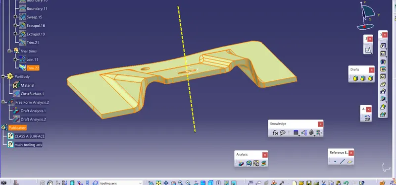
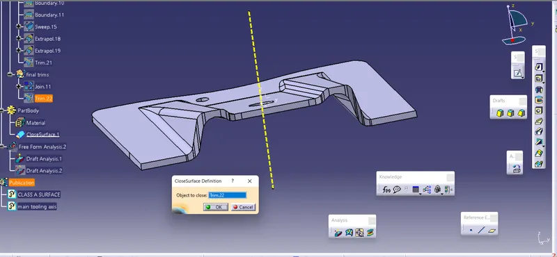
CREATION OF THE SOLID
- the solid is created from the surface body using the closed body option
FINAL DRAFT:
- the solid body is then draft analysed to see if the final body can be cleared using the main tooling axis
- the green colour of the draft is ensured and is adjusted to arrive at the result