Week 8 - Challenge 4 - Coin Holder Design
CREATION OF TOOLING AXIS , CLASS B AND C AND DRAFT ANALYSIS OF COIN HOLDER
TOOLING AXIS
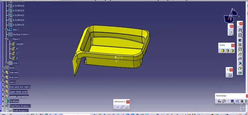
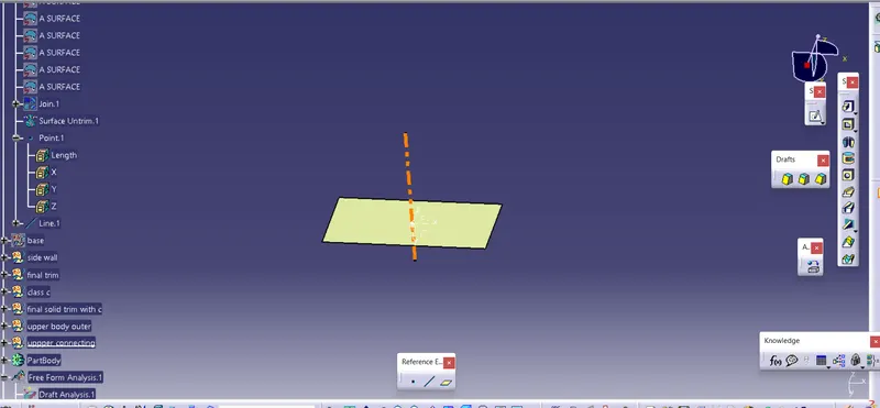
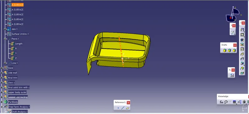
- here the tooling axis is created by extracting the base and mid point is created on the base
- then a line drwan in z direction using the midpoint
- here bisecting method is not used because the mid line itself cleares faces
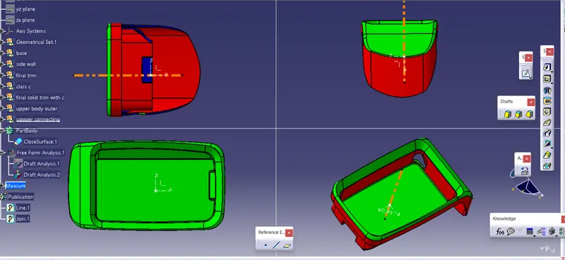
- draft analysis is made to conform the tooling axis
- we can see from draft analysis that the side walls are not clearing and this can be rectified by the styling engineer to create draft on those faces
CLASS B
BASE
- the extracted base for the tooling axis is used
- another sturcture like a dent in the bottom is also extracted and
- both the base and the structure and trimmed offseted to 2.5mm
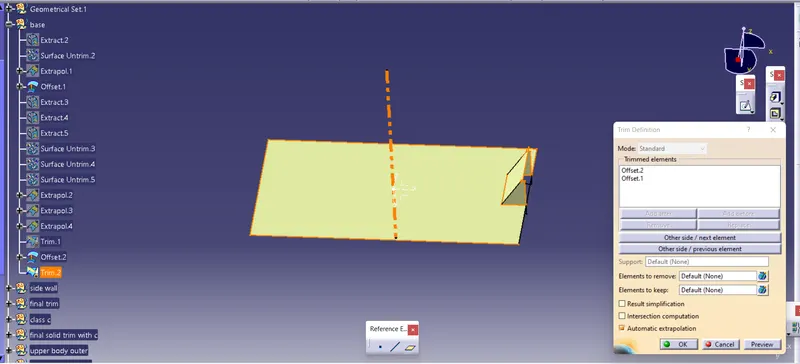
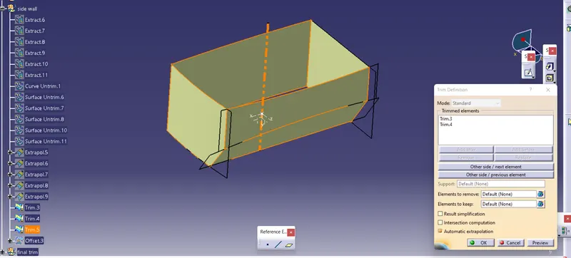
SIDE WALL
- the side wall is the cavity area of the coin holder is extracted
- they are also untrimmed and are extrapolated
- then they are trimmed together offseted to 2.5mm
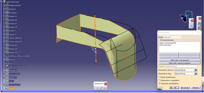
UPPER BODY OUTER
- the upper outer surface is first extracted and then the faces are extapolated using smooth curves
- then it is extended futher till intersecting each other
- finally the adjacent faces are joined together and they are trimmed offseted to 2.5mm
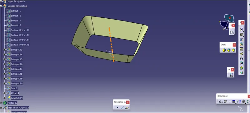
UPPER BODY CONNECTIVE
- the upper outer coonnecting faces are first extracted and they are made untrimmed
- they are also extrapolated untill they intersect each other
- then they are trimmed and offseted to 2.5mm
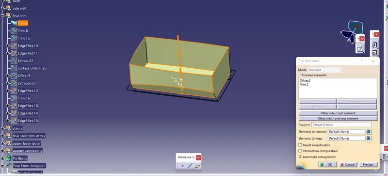
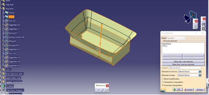
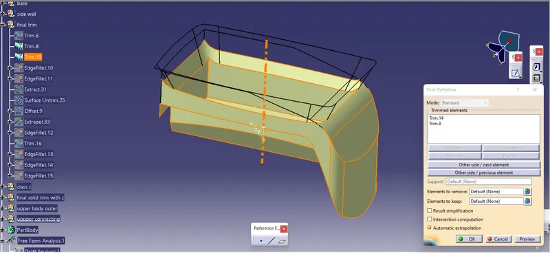
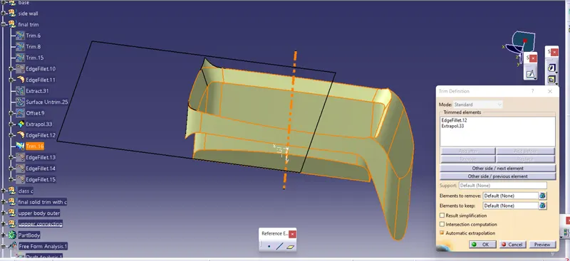
FINAL TRIM
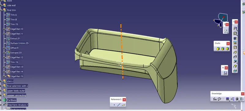
- the trim of the base and the trim of the side wall are first trimmed together
- then this trim is trimmed with the outer body connetive
- they it is trimmed with the outer body surface
- this gives the final b
- but a small parch got peeped out of the class a
- this is rectified by using the small patch left out and trimming the final bsu
- now the desired class b is created
CLASS C
MAIN CLASS C
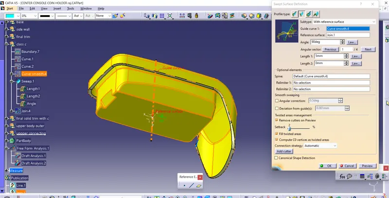
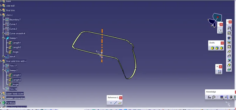
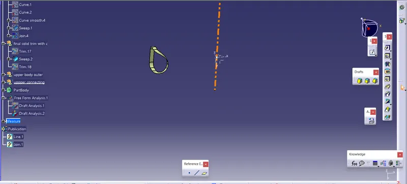
- the main class c is created using the outer class a surface and creating boundry and is diassembled into two components
- one major one and that is then made into smooth curve and then it is sweeped using the referance surface sweep and a angle of 90 deg is given
- then this is joined to the class a
UNDERCUT C
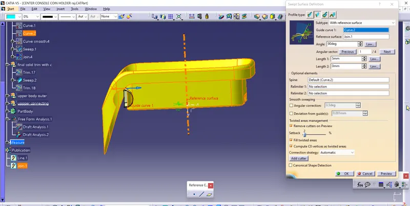
- another disassembled boundry is the under cut
- it is then made into smooth curve and it is also sweeped using the referace surface option
- then it is also joined to the class a
FINAL SOLID TRIM
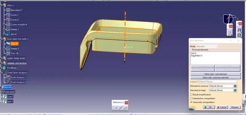
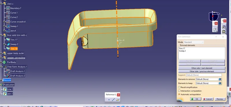
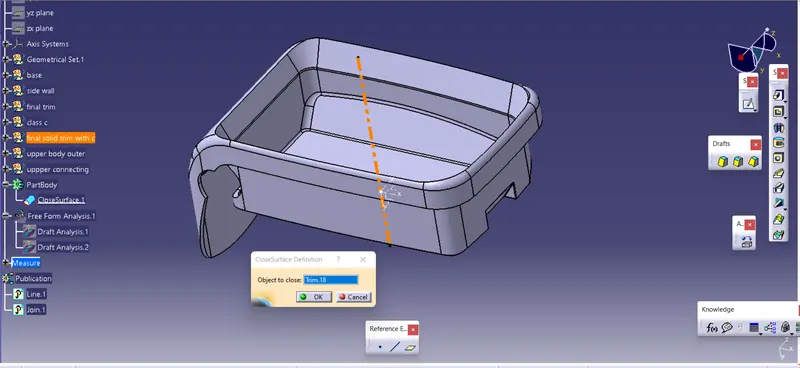
- now the joined class a is trimmed with the class b
- then a closed surface is obtained and then it is converted into solid by the closed surface option
FINAL DRAFT
- the final draft is created in the solid formed
- the draft results show the red colour in the side wall and it can be rectified only by working on the class a by styling designer