Bird Strike - Project - 2
Aim-
- To perform and simulate the non-linear case of Birdstrike in Aero-engine using explicit analysis in LS-Dyna.
Objective-
- The FE model consists of 4 parts that need to be separated and save part-wise. The suitable material is created and saved in a subfolder.
- The node number, element number, and part number are assigned as mentioned above. Also, to conclude the final simulation create the main file with the *include file and run the explicit simulation using mass scaling.
Theory-
- Bird strikes pose a significant threat to aircraft structures, as contact with a bird while in flight can cause significant structural damage.
- For more than 30 years, computational approaches have been used to design birdproof structures, and they have proven to be a cost-effective alternative to costly physical certification testing with live birds.
- The bird behaves as a soft body and flows over the target structure in a fluidlike way at the velocities of interest, with the high deformations of the spreading material being a substantial problem for finite element simulations.
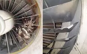
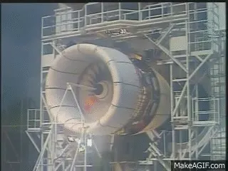
Procedure-
Case setup
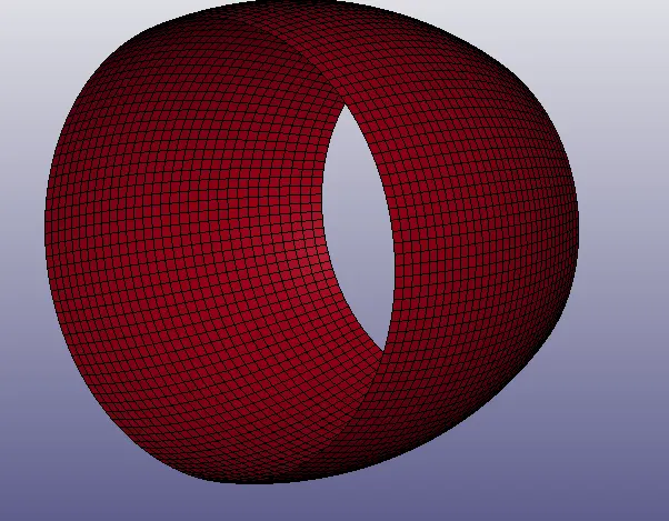
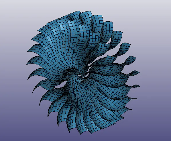
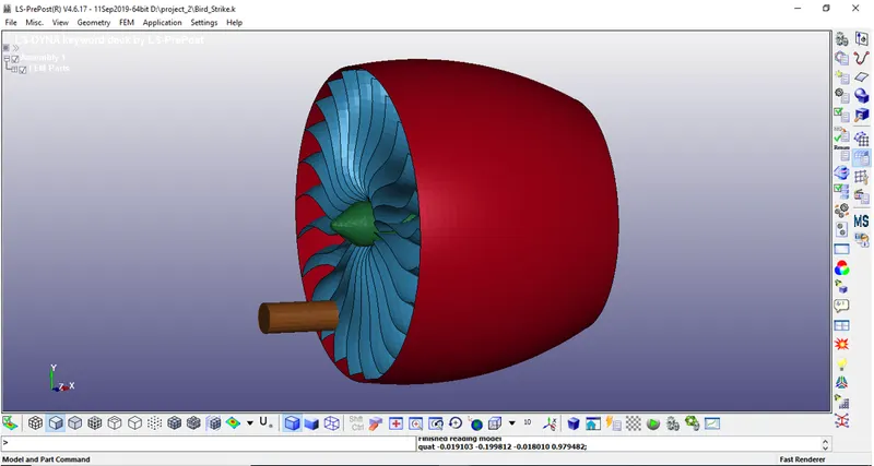
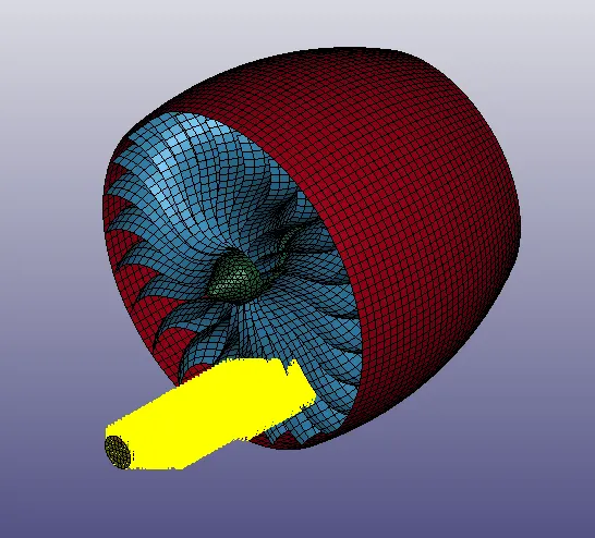
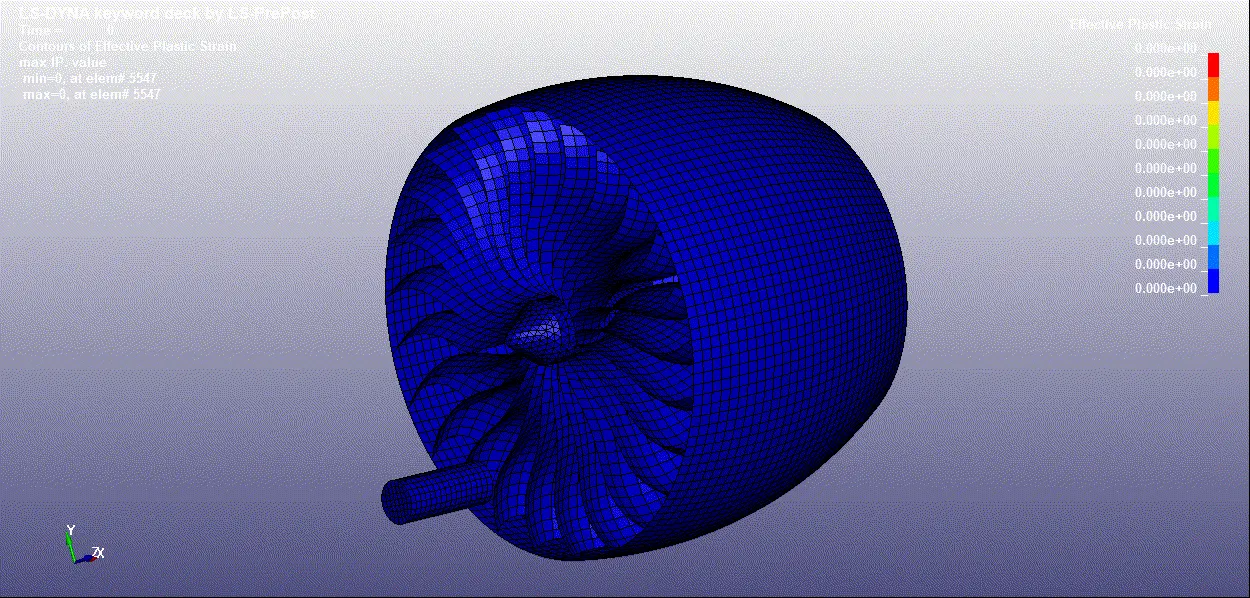
- The given keyword file BIRD_STRIKE consists of nodes and elements for all the four parts collectively i.e, Engine casing, Blade, Hub, and Blade
1}:- Casing
2}:- Blades
3}:- Bird
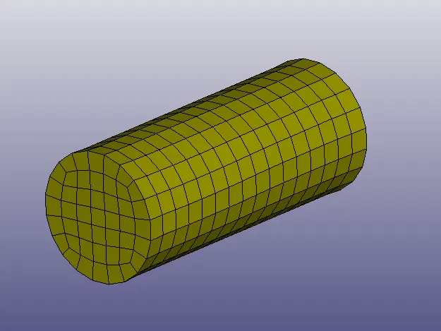
4}:- Hub
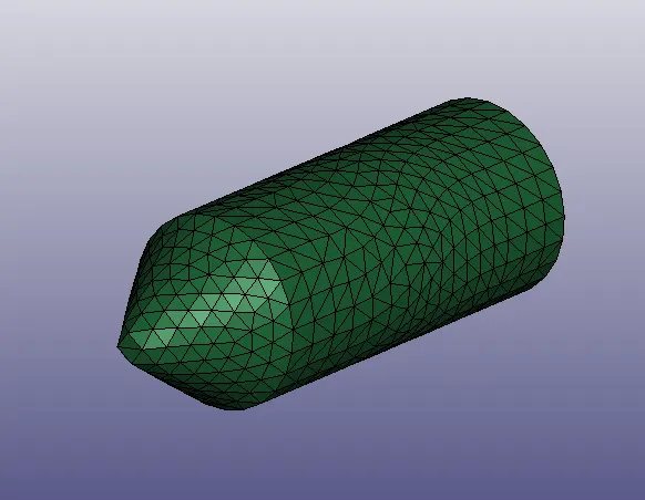
Note-For this FE model the unit system followed here will be Kg, mm, ms.
- Now we will take each part seperatley and create the material card and section cards accordingly.
Step 1:- Open Bird_Strike.k File
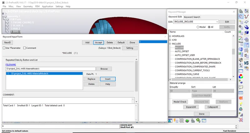
Creat *Includ Card And Includ AL-4495-MaterialModel.k File . Then Save It
Then Open Result_Bird_Strike.k File
Step2:- Creat Sections, Materials And Assign To All Parts .
- For ENGINE CASING
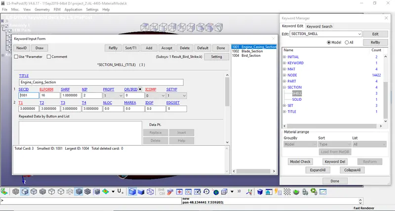
{*Section_Shell}
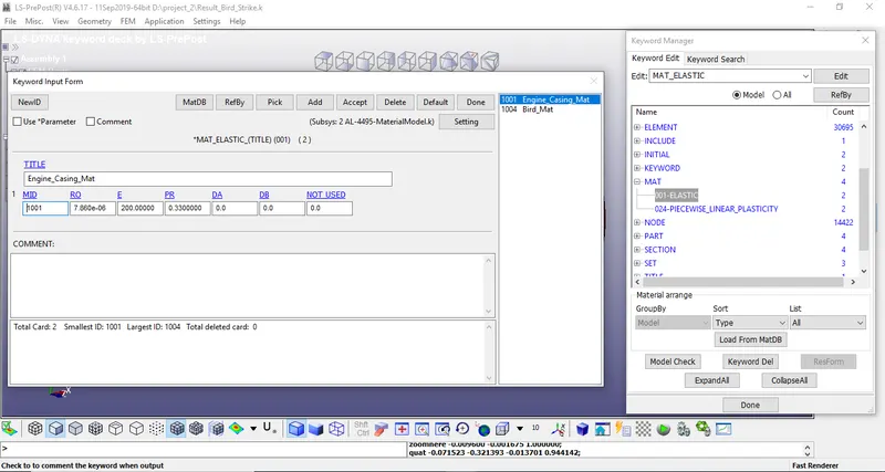
{Mat_Elastic}
- As per data given in project problem statement that we have to use elastic mat card with E value as 2000GPa, so we will so the same.
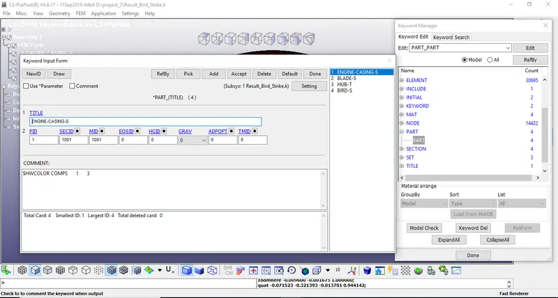
Assign To Parts
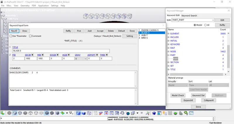
- For BLADE
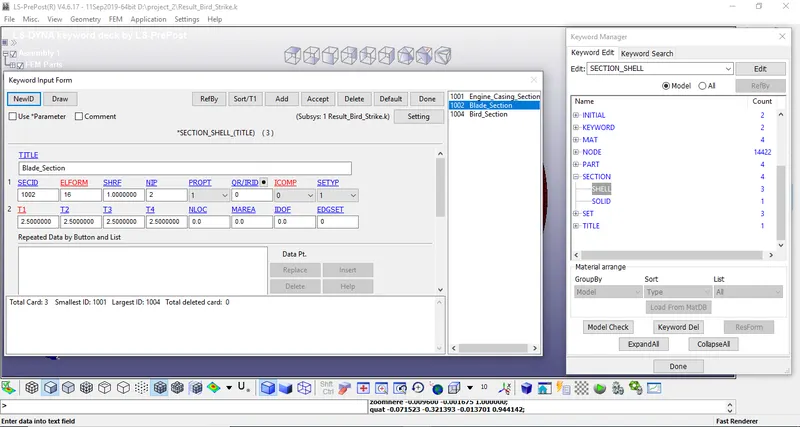
{*Section_Shell}
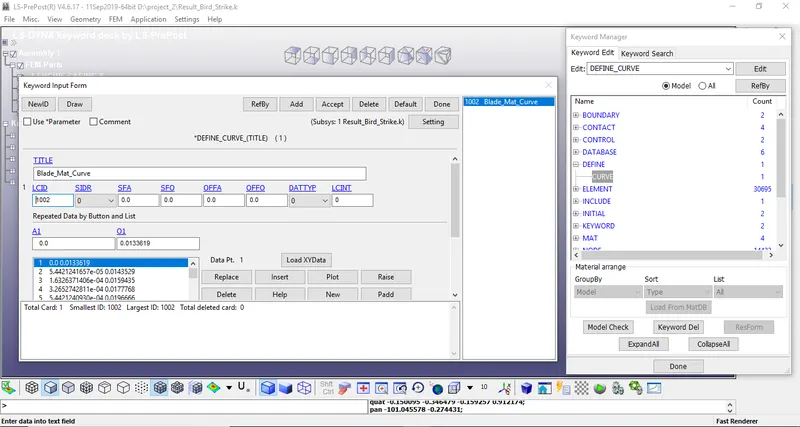
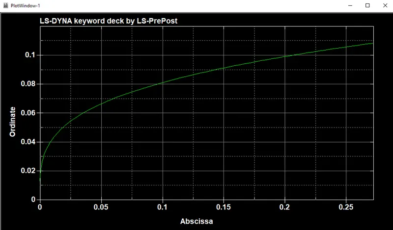
load_curve
- Now weill define a curve as per given in the mat card and assign it to the model mat card.
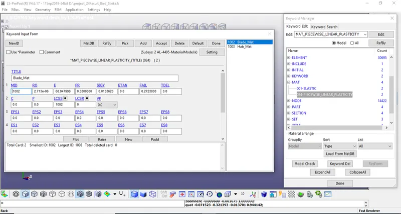
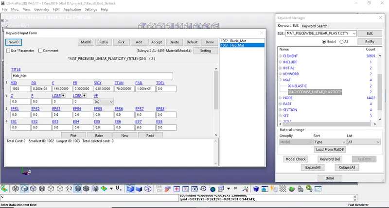
{Mat_Piecewise_Linear_}
- As per data given in project problem statement that we have given a material type which we have to use for blade, so we will use same material card with piecewise linear plasticity_024, and also assign a curve for same.
Assign To Parts
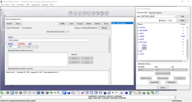
- For HUB
{*Section_Solid}
{Mat_Piecewise_Linear_}
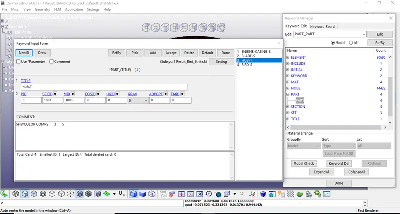
Assign To Parts
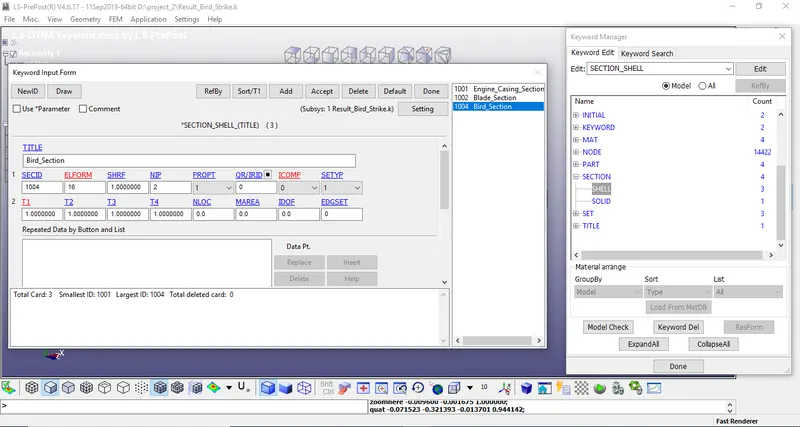
- For BIRD
{*Section_Shell}
{Mat_Elastic}
- As per data given in project problem statement that we have to use elastic mat card with E value as 2000MPa, so we will so the same.
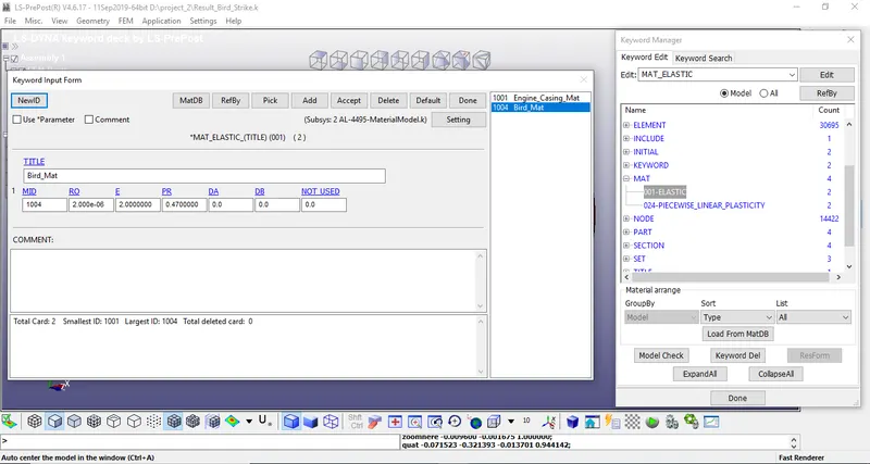
Assign To Parts
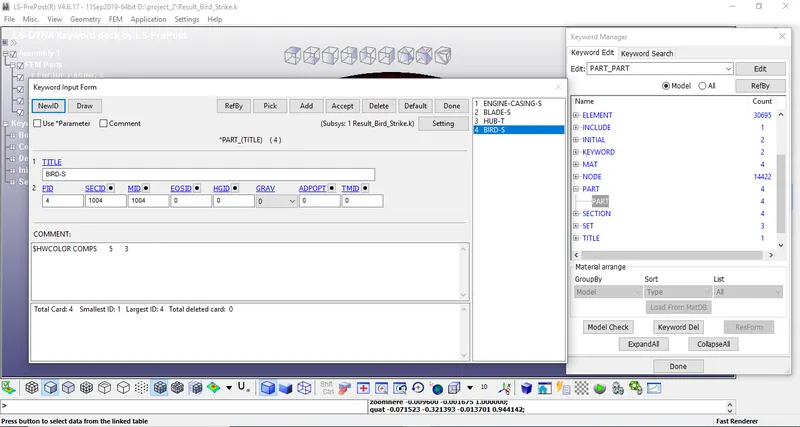
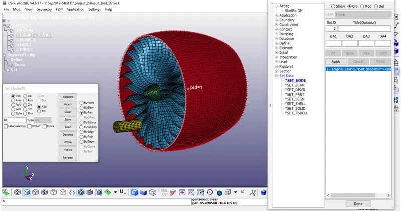
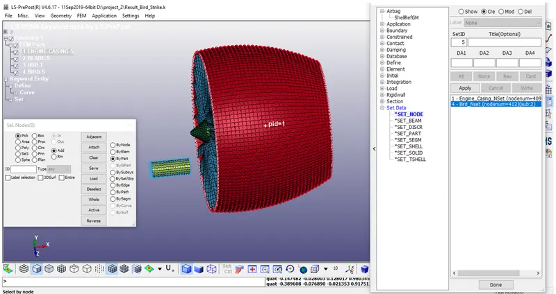
Step 3:- Craet NodeSets
1}:-Engine Casing
2};- Blad,Hub
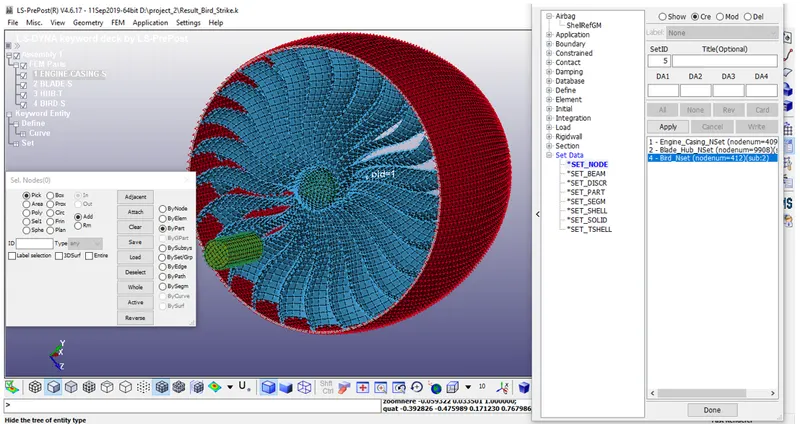
4}:-Bird
Step 4:- Creat Contact Cards
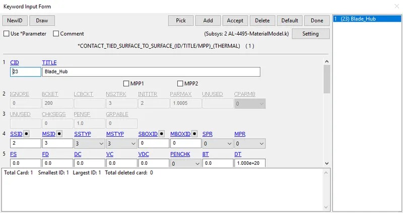
- Now we have to create contacts between the parts one by one.
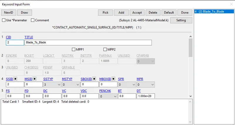
2}:-
- Finally we have to create the singlre surface contact for blades only.
- Eventually, once the bird hits the blades the deformed blades not supposed to penetrate with each other.
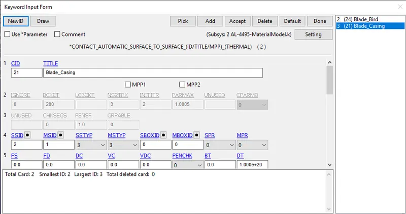
21}:-
- Now third contact is between blades and casing, where casing is master and blades are slave.
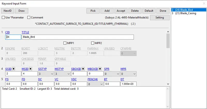
24}:-
- Now second contact is between blades and bird, where bird is master and blades are slave.
23}:-
- firstly we will create contact tied surface to surface between hub and blade where hub is master and blade is slave.
Step 5:- Creat Initial Velocity
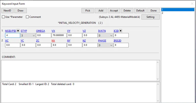
- The average velocity of the bird travels from the references is observed to be approximately 20 to 80 mm/ms.
- Here the velocity of the bird is assigned to be VX=70 mm/ms along the X-axis translative direction.
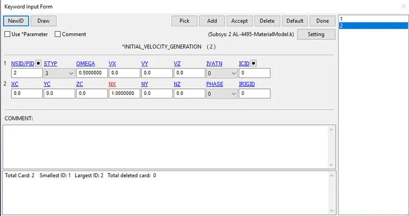
- The angular velocity of the blades is roughly around an average speed of around 3000 to 20000 RPM.
- Considering 5000 rpm and convert it to radiant. From which angular velocity OMEGA=0.5 rad/ms, NX=1 (x-direction cosine).
Step 6:-Craet Control Terminetion And Timestep.
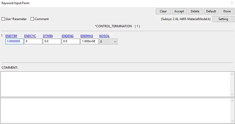
we have to define control termination card, For that go to Model and part> Keyword manager> All> Control> Termination, Provide the End time is 3 ms
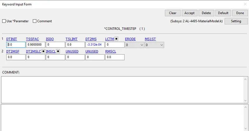
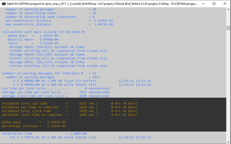
- Control Time step card is also defined with experimenting the percentage mass scale to be upto 8%.
- Now we will create the database file.
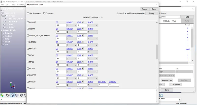
- BINARY_D3PLOT - It defines the frequency at which the animation file is to be created and is set to 0.1ms
- Now we will create the ASCII files.
The output request in ASCII format, The following keyword are activated
- GLSTAT- Global Data
- MATSUM- Material Energies and
- NODOUT- Nodal point data
- Now we will check the model and then head for simulation.
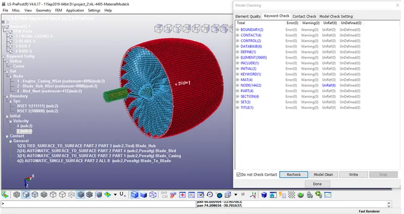
- Since there is no error we can proceed further to save and run the keyword file.
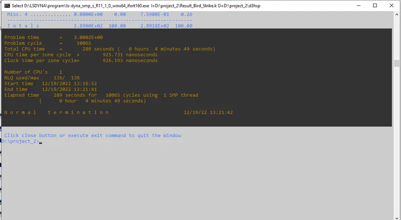
- As simulation ended with Normal Termination. Therefore, the model is simulated successfully.
- Now we can open this files one by one using LS-post processor.
Results & Plots-
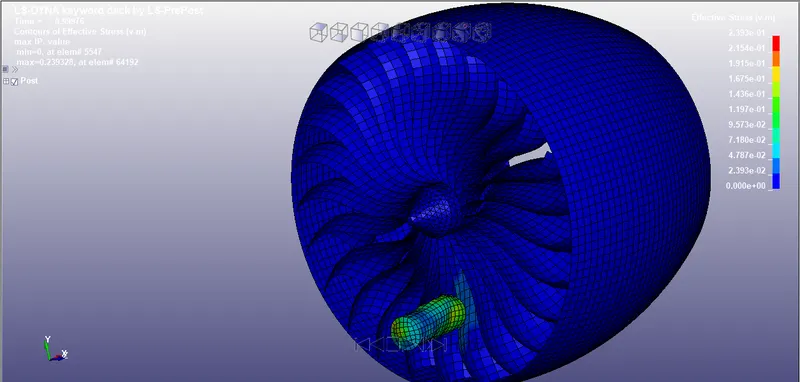
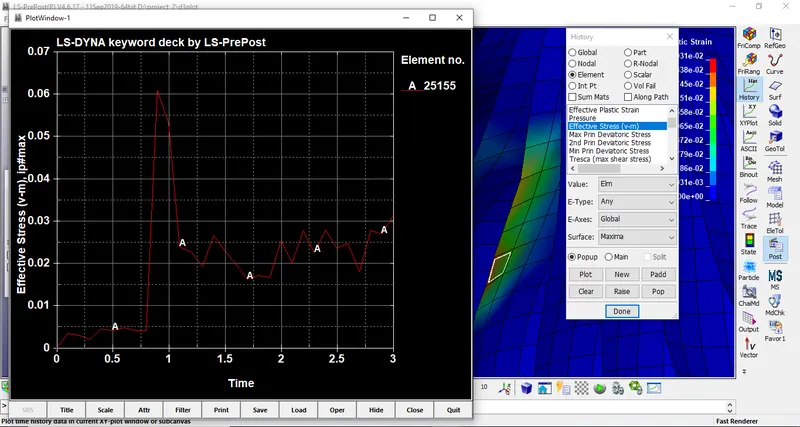
Effective Stress (V-M)-
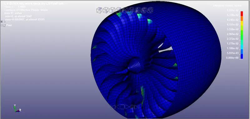
Effective plastic strain-
Plots:-
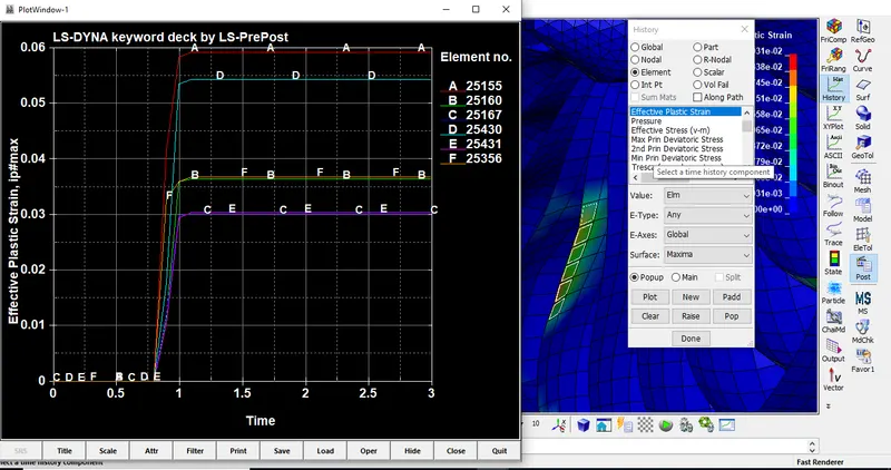
Effective Stress at Element 25155
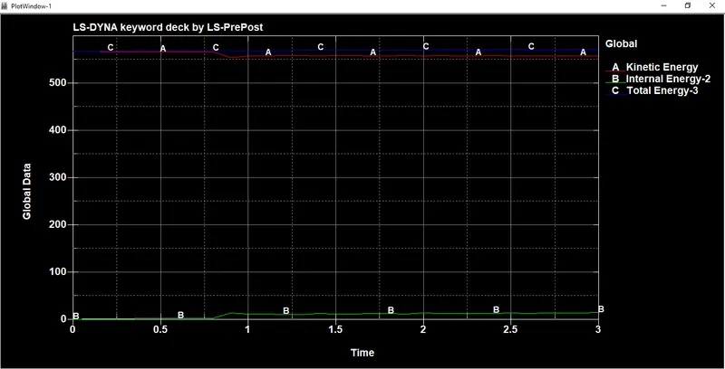
- In this Explicit Analysis, when the bird hits the blade at a velocity of 70kmph. The Internal energy increases and kinetic energy decreases due to the impact on the blades.
- There is no hourglass formation due to full integration ELFORM-16 is used the total energy of the system remains constant throughout the simulation.
- Hence we can notice that the plot satisfies the law of conservation of energy.
Animations-
Effective Stress (V-M)-
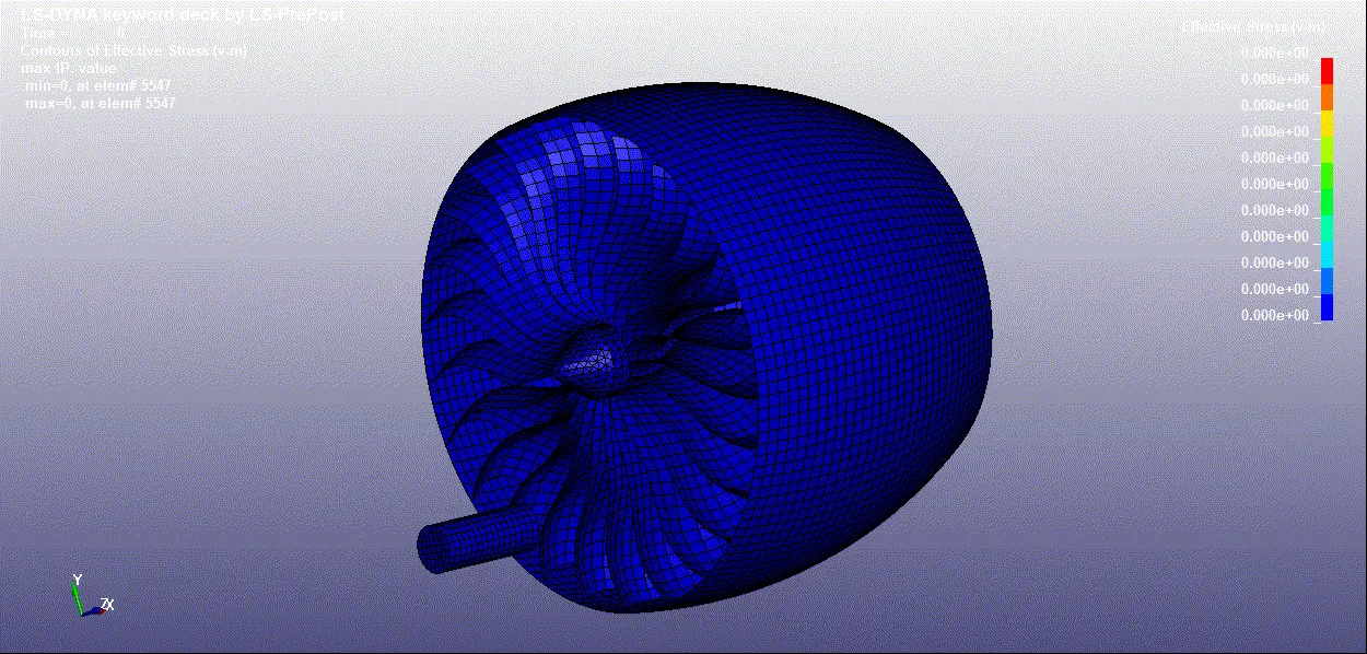
Effective plastic strain-
Conclusion-
- All the components are following a consistent number pattern for each element, node, and part as followed in many Industries.
- All the files such as for component, BC's, contact, control, database are included in the Main file. The BC and load conditions are mimicking the real-world scenario.
- For Mass-scaling, the % mass added is 8% which accepted value. From the energy plot, we can observe that total energy is constant over the simulation which represents the simulation runs well(1st check).