Week - 3 Drop test Challenge
Aim-
To create a complete simulation file to perform a drop test from given basic .k file consisting of only nodes and elements. Essential keywords should be added to create a basic solver deck to simulate a drop test.
Procedure-
- Open the LS-PrePost and open the given keyword file.
- The given input file consists of three different parts the bottom plate of shell elements, the mobile phone of solid elements and the bottom plate as solid elements. We can either model the test with a bottom plate as a shell or solid elements.
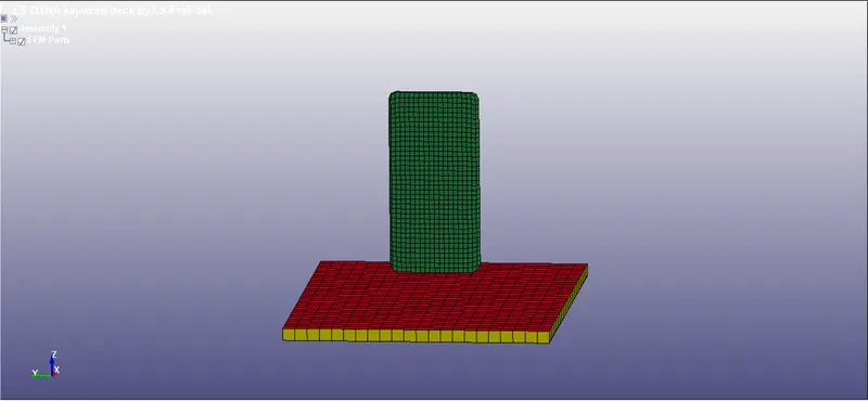
- As per above image, we have sheet made of shell elements in red color.
- We can do analysis with considering sheet as a Rigid Wall of below solid plate as a rigid wall.
- For easy way to handle the Phone as well as Rigid wall, we can use solid rigid wall. So we can delete red color sheet part.
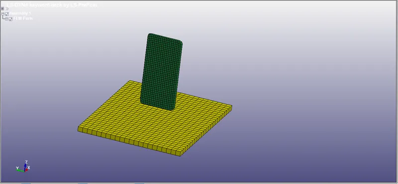
- Now we have to select the material card for mobile and rigid wall.
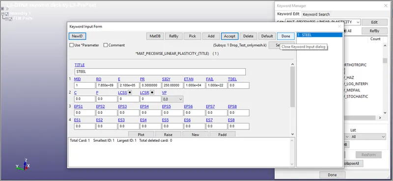
- For mobile we can select steel as material and for this we will select 024-PIECEWISE_LINEAR_PLASTICITY card.
- For selecting material go to keyward>>all>>mat>>select material card as 024.
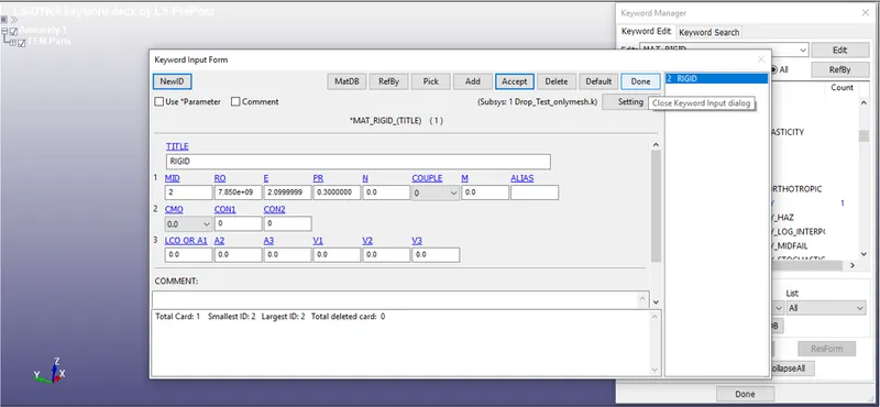
- For rigid wall will select the same steel material with card as 020-MAT_RIGID.
- Here we have to input material properties like, density, young's modulus, poisson's ratio etc.
- Similarly, we have to define section card for assigning element type as solid. Select *SECTION_SOLID card and define required properties.
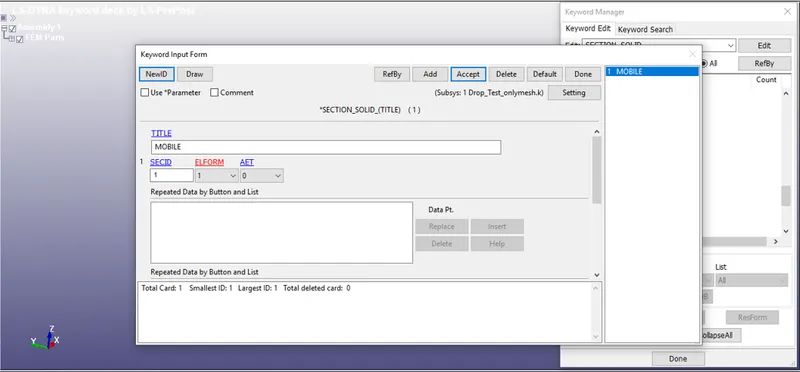
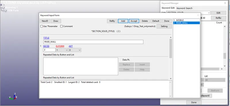
- Now assign the above generated material and section to the each parts.
- For that we have to go to part and have to select section and mat card for each part.
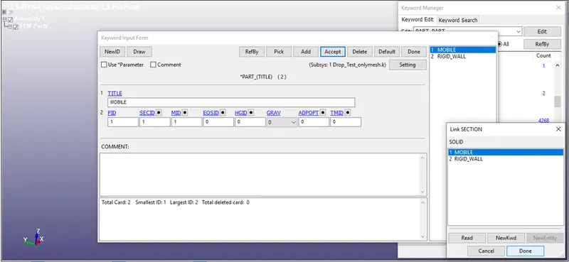
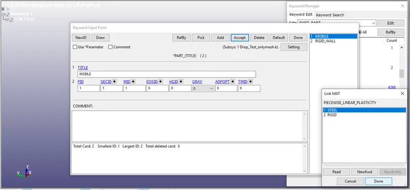
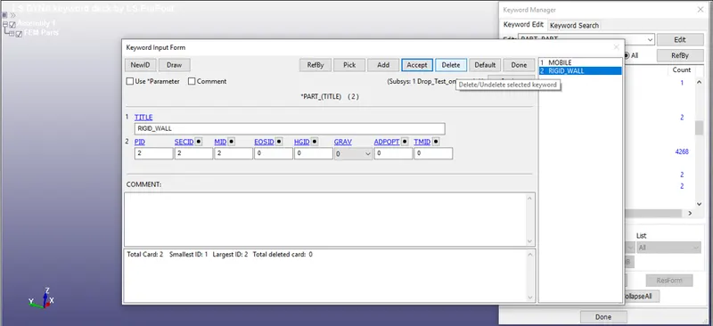
- Once we have defined the section and mat card to parts no go to define the boundary conditions.
- Now, assign proper boundary condition to the parts. This can be done by going through create an entity and selecting required boundary conditions.
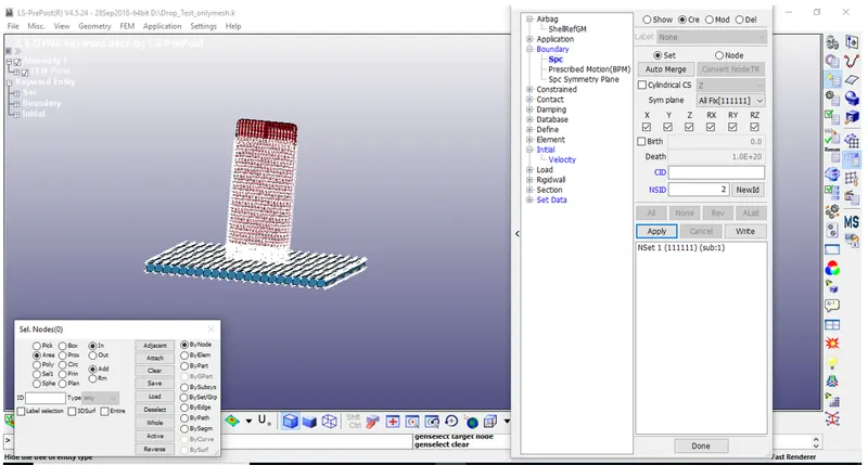
- The bottom plate is fixed by constraining the boundary elements of the plate in all the degree of freedoms. The selection of part is done by area. Boundary>Spc(Single point constraint) option is utilized for defining this boundary condition.
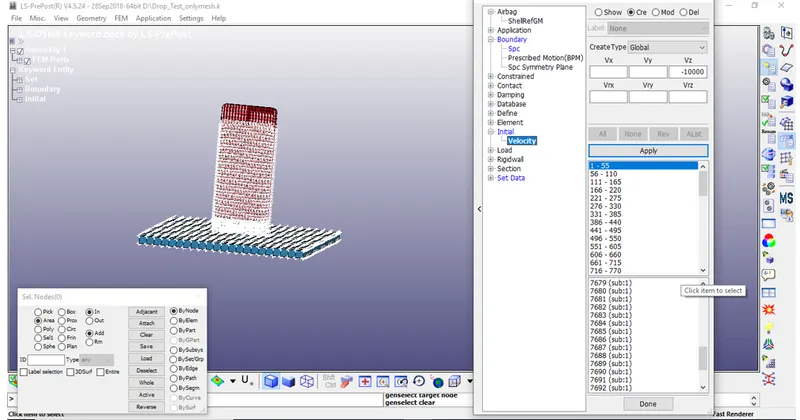
- Similarly, the velocity of 10000mm/s is given through *INITIAL_VELOCITY card available in create entity toolbar. The mobile phone is selected by picking the part option. In negative Z direction.
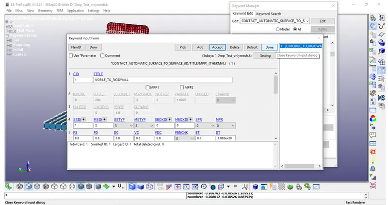
- The contact between the two parts is an important parameter. This is defined by *CONTACT_AUTOMATIC_SURFACE_TO_SURFACE card. The slave segment(SSTYP) and master segment(MSTYP) set type is defined as part ID. Slave segment is defined as a mobile phone and master segment is defined as the bottom plate.
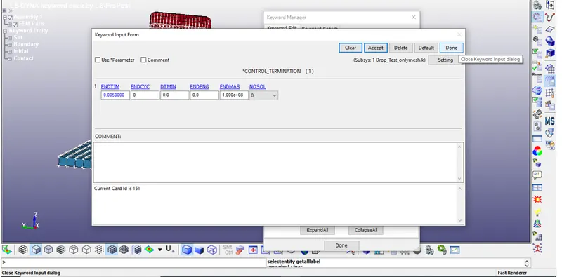
- The termination time for the problem is defined by *CONTROL_TERMINATION card. The distance between the mobile phone and the bottom plate is calculated and the approximate time taken to hit the bottom plate and some additional time after the impact is calculated. This cumulative time (0.005 s) is defined as termination time in the card.
- For doing so go to keyword manager>>all>>control>>termination.
- Now after all conditions and termination details generated, we can generate output requests or results what we want from the analysis.
- For that, we have to create cards for output. For animation and other part related data, create “BINARY_D3PLOT”, from database and “GLSTAT”, “RCFORC”, from ASCII_option in database.
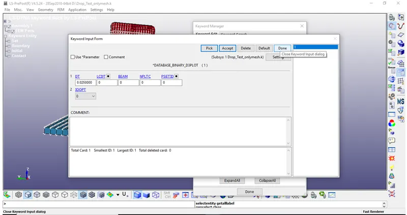
- After creation of all necessary cards, save the Keyword file with “.K” extension.
Calculation-
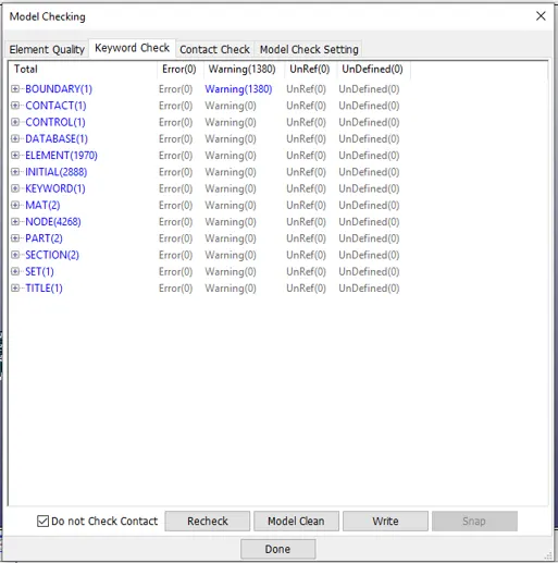
- Before going to run simulation we have to do the model check, here we can ignore the warnings.
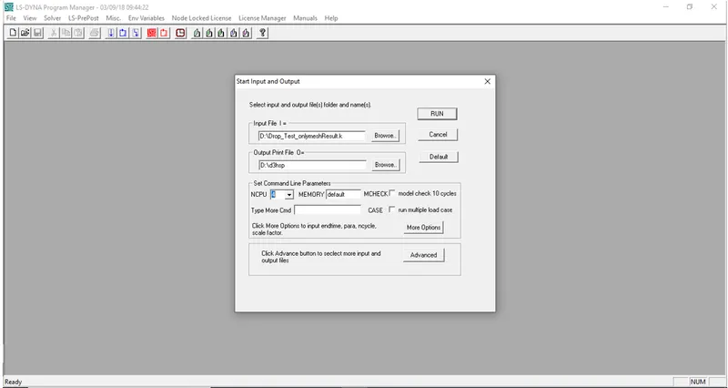
- For running the simulation we have to go to LS-run and need to select the .k extension file.
- Now for calculation of all analysis, run the simulation as per availability of the core of CPU bu giving the value in “NCPU”.
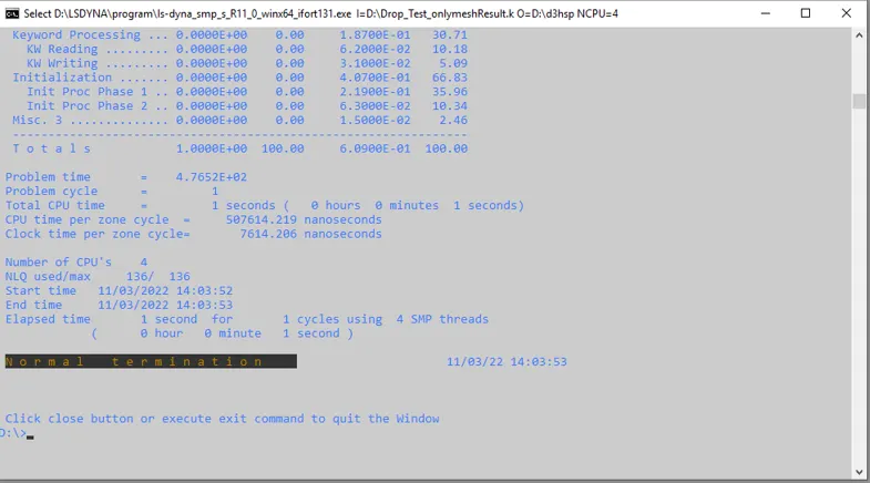
- Note that normal termination means our simulation has been ran properky and no issues are found.
Results-
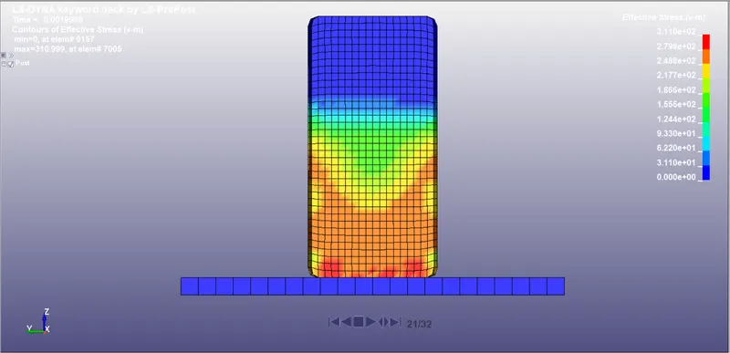
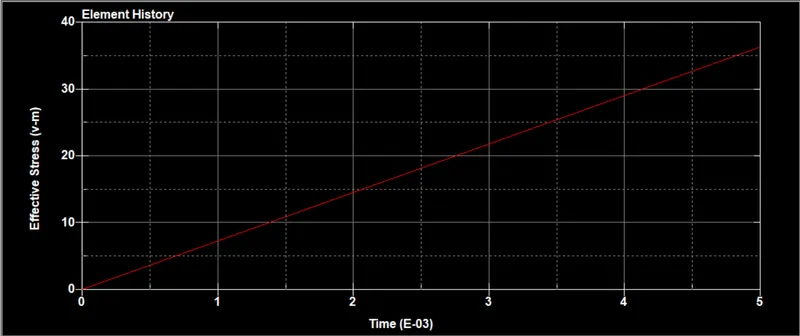
Von-Mises Stress-
Force plots-
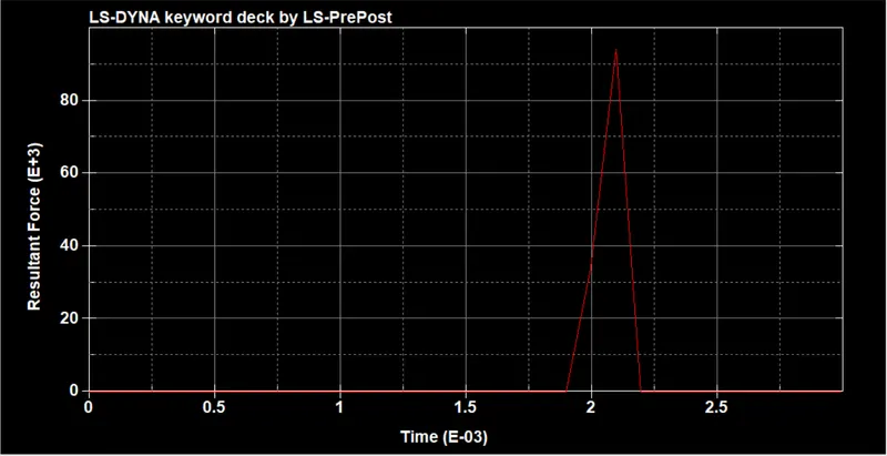
Resultant-
Displacement-
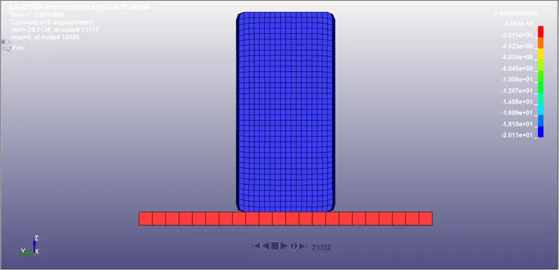
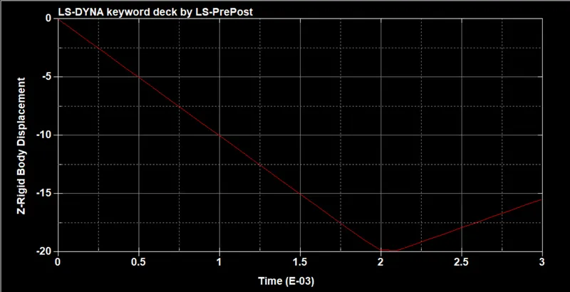
Velocity Plot-
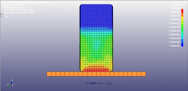
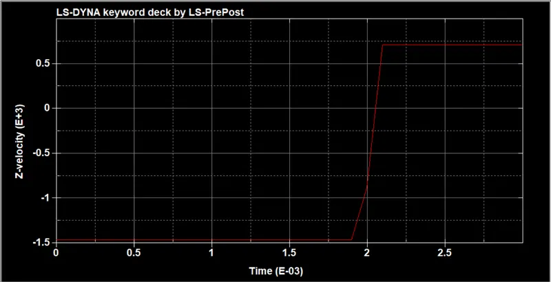
Conclusion:
This concludes Material modeling strategy considerably acceptable for this case; however different Material model should be checked with different loading condition to arrive at correctness of modeling strategy of the simulation. The simulation results adds confidence to the Material modeling approach and endorses the mesh size, element selection and contact definitions specific for problem describe in this analysis. This drop test simulation helps to improve the design of Cellphone while it is in design life cycle. We can try different Material models and also check for the various output results for more accurate results.