Project 1 - 2D meshing on the instrumental Panel
AIM : To diploy 2D mesh for the given CAD model.
procedure :
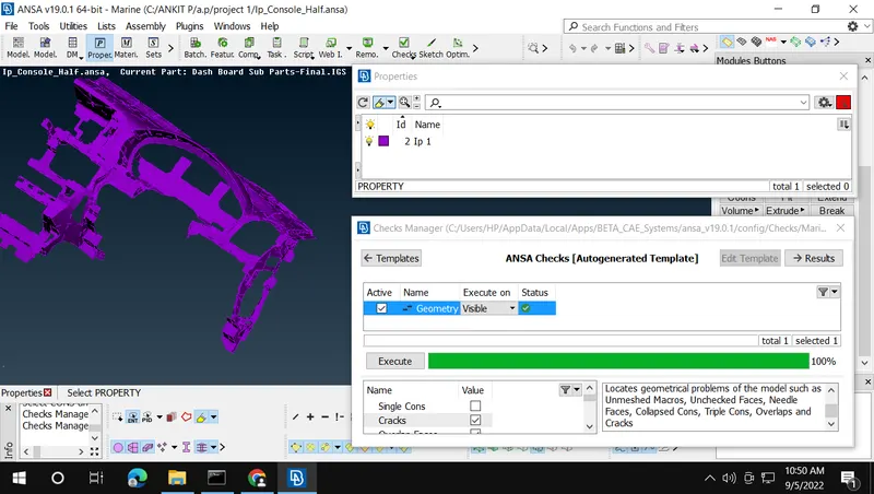
- First,we should check the geomentrical errors in CHECKS MANAGER and fix them.
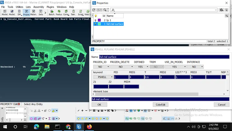
- This model IP console is aplastic component it contains varying thickness.so,try to measure the entire model and set PID for the model.
- now,mid-surface of the model should be taken using different tools at different regions according to the requirement.
- Some rules of thumb when meshing:
- The mesh should look rather smooth and regular
- Use the simplest element type suited for the problem.
- Start with a coarse mesh and understand the modeling results; then use a finer mesh if needed.
- Try to keep mesh related uncertainties to a minimum if possible. Keep it simple as it can get more complicated on its own.
- The mixed mode element type is the most common element type used due to the better mesh pattern that it produces (restriction: total tria % <5). Sometimes for structural analysis or for convergence and better results for a non linear analysis, the pure quadrilateral element meshing option is selected.
-
- How Not to Mesh
- Back to back triangles should be avoided. Two tria elements should not be connected to each other directly.
- On plane surfaces triangular element should be avoided.
- No mesh transition on constant radius fillets / curvatures
- Circular holes should be modelled carefully with a washer (1.5 to 2 times diameter) and a minimum of two layers around the hole.
- Holes should be modelled with an even number of equally spaced elements: For a better representation of the hole geometry and smooth mesh flow lines, holes should be modelled with an even number of elements (like 6, 8, 12,16 etc. rather than 5, 7, 9 or 13).
- Nodes should lie properly on the surface, with no deviation (and no kinks).
- Follow the feature lines (nodes should lie exactly on the edges).
- Instead of a zig-zag distribution, a structured or smooth mesh is recommended
- For crash analysis, follow the mesh flow line requirement
- For crash analysis, rotating quads are not Recommended.
- For crash analysis, constant mesh size (by using trias) is preferred (due to a minimum element length and a time step criteria).
- How Not to Mesh
Step 1 :- I check for the geometrical error. and clean the geometry 100%.
Step 2 :- Make Mid Surface one by one for total geometry with its thickness of 0.6mm.
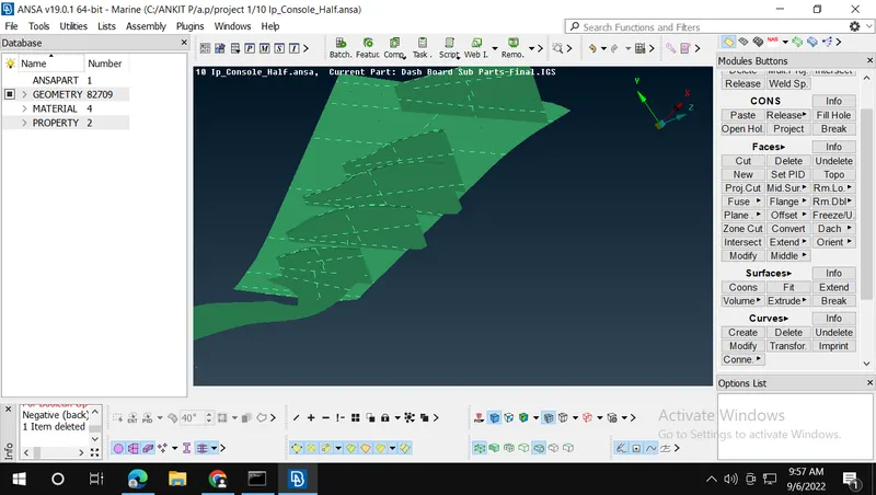
use measure option and try to mesure the thickness of the buttons using other entities.
total thicness =3.5
base thicness=0.6
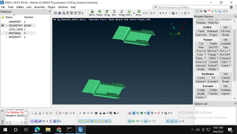
Use Measure option and try to mesure the thickness of the buttons using other entities.
total thicness =3.5
base thicness=0.6
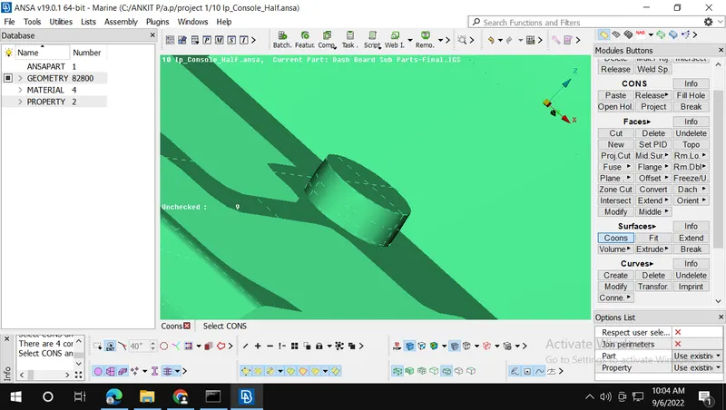
Step 3 :- Make Mid Surface Meshing with given element Quality criteria.
Quality Criteria:
|
S.No |
Quality Criteria |
Value |
|
1 |
Target/Average length |
4 |
|
2 |
Minimum Length |
2 |
|
3 |
Maximum Length |
6 |
|
4 |
Aspect |
3 |
|
5 |
Warpage |
15 |
|
6 |
Skewness |
45 |
|
7 |
Jacobian |
0.7 |
|
8 |
Minimum Quad Angle |
45 |
|
9 |
Maximum Quad Angle |
135 |
|
10 |
Minimum Tria Angle |
30 |
|
11 |
Maximum Tria Angle |
120 |
|
10 |
Tria Percentage |
15 |
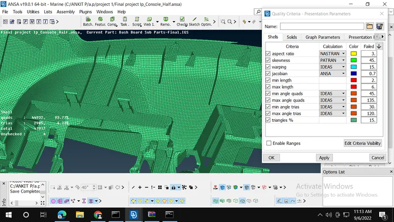
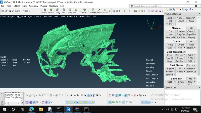
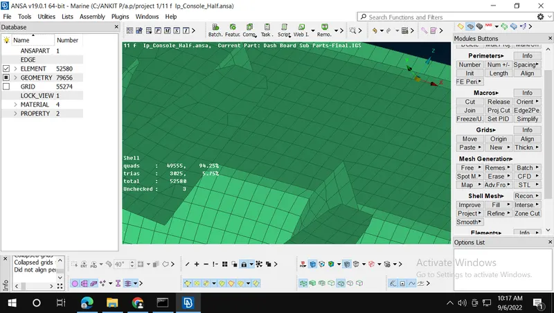
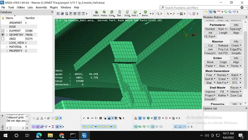
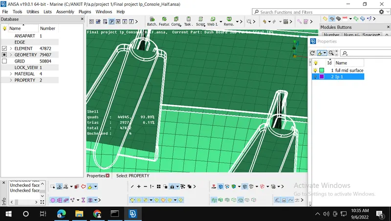
TO VIEW THE SHELL SOILD PRESS F11 >GO TO THE PRENSENTATION OF PARAMETR>CHECK THE DRAW SHELL SOILD.
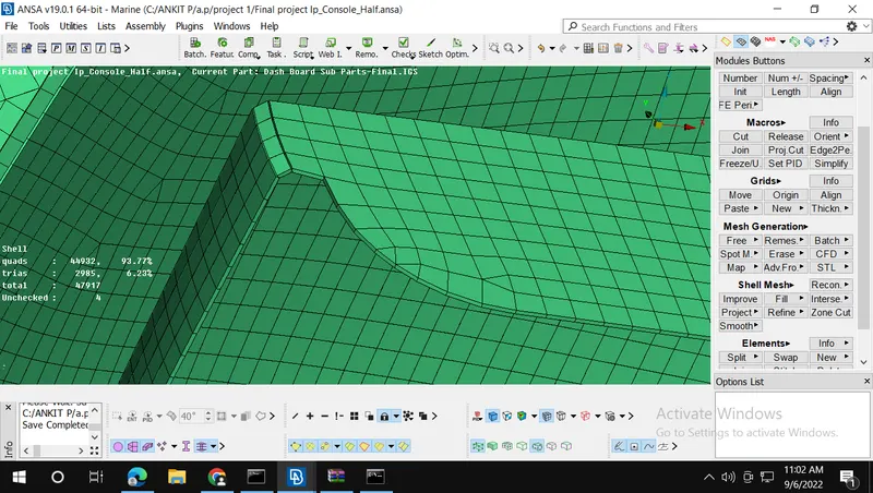
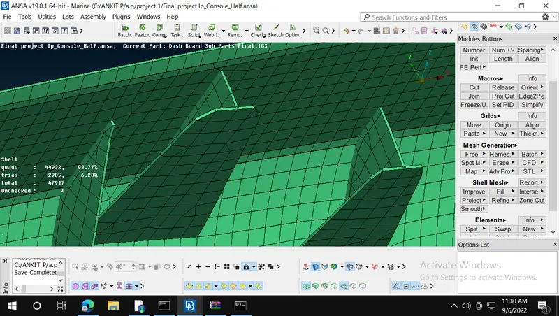
Possible Outcome :-
- how to get mid-surface for complicated plastic components.
- how to achieve a proper 2D mesh flow.
- how to use different tools according to the requirememt.
RESULT AND LEARNING OUT COME:-
- IN this assign-ment we learn the how to mesh the such complex part in automobile like dash board
- how to mesh the part by part and how to get feature
- how to use the mesh parameter and meshing feature in mehsh module etc..
Project File Link:- https://drive.google.com/file/d/1iqUHZJ9vcLqWju81537Plj1Cc9FnGSrN/view?usp=drivesdk