Assignment 3-2D Element Formulation Challenge
AIM
- The aim is to run the simulation on crash beam model with base simulation (default values in hypermesh) and improved shell element properties (recommended properties)
|
Parameters |
value |
Description |
|
Ishell |
24 |
QEPH 4 nodes shells are best combination of cost and accuracy |
|
Ismstr |
2 |
Full geometric nonlinearities (default)with possible small strain formulation activation in RADIOSS Engine |
|
Ish3n |
2 |
Standard 3 noded shell (C0) with modification for large rotation(default) |
|
N |
5 |
Number of integration points set to 5 for accuracy bending |
|
Ithick |
1 |
Thickness change is considered for accuracy |
|
Iplas |
1 |
Iterative plasticity for good accuracy. |
- Change the elemental properties as mentioned below and check whether the results are acceptable then compare the results with the base simulation.
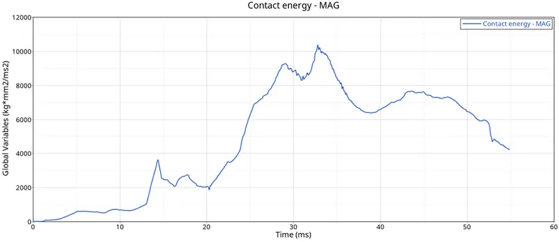
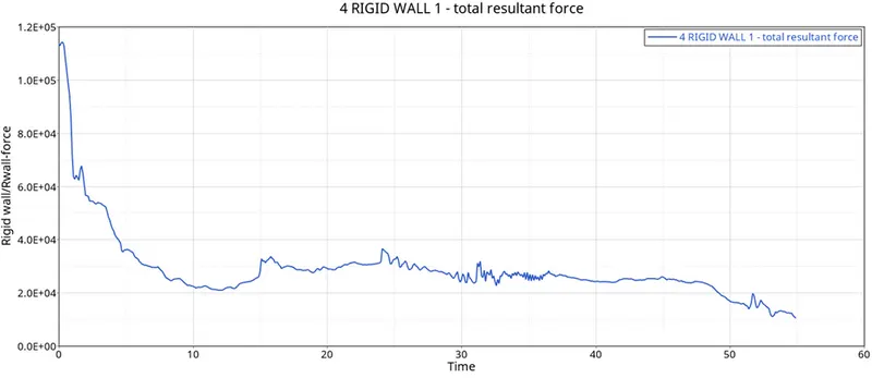
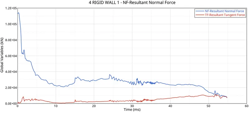
- Study the output of both the simulation by plotting Rigid wall forces and Energies like internal energy, Hourglass energy, Contact energy and Total energy.
Objective:
1. Using the crash beam file from the previous assignment, change the run time to 55 ms.
2. Change the number of animation steps during simulation to a minimum of 25 and a maximum of 60.
3. Run the base simulation without any modification to element properties.
4. At the end of the simulation, do the energy error and mass error checks and determine whether the results would be acceptable.
5. If acceptable, Plot rigid wall forces, internal energy, hourglass energy, contact energy, the total energy of the simulations.
6. Change all the shell elements properties to recommended properties, save this as separate, rad files and run the simulation.
7. Follow steps 5 and 6.
8. Create a brief report comparing all the results from steps 5 and 6 for both simulations.
9.Comment whether there is any change in the results and why there is any change in the result.
What is Hourglass?
- It is weird mode of deformation that occurs in under integrated shell elements where no stresses are produced. As stresses are not produced, it reduces the accuracy and true response of the structure. This leads to inaccurate strain and displacement results with unrealistic deformations.
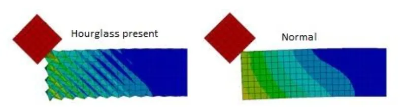
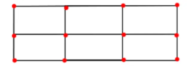
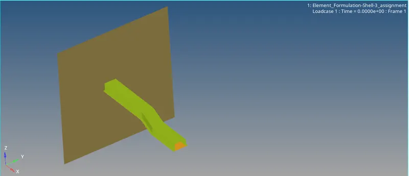
BEFORE HOURGLASS EFFECT
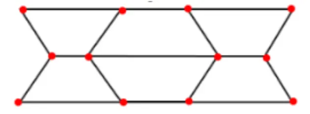
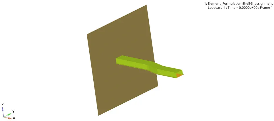
AFTER HOURGLASS EFFECT
When do we say that hourglass is produced?
- In an under-integrated element, displacements and forces exist for each node of the element. If the summation of all these forces and displacements provides zero stress and strain on the integration point of the element, then that element fails to calculate the stiffness for the mode of deformation. Due to no stiffness calculation, the deformation happens in a very weird manner. This is when we call, the element has entered into hourglass.
How is hourglass controlled?
- As mentioned before, the hourglass occurs only at the under integrated shell elements. To avoid hourglass, we go with reduced integration elements. We saw two types of reduced integration shell elements: Ishell=1,2,3,4 and Ishell=24, The control of hourglass also changes on the type of shell elements used. Ishell=1,2,3,4 (Q4) employs perturbation method for controlling hourglass. Ishell=24 (QEPH) employs a physical stabilization method for controlling hourglass.
- Perturbation Method: In Ishell=1,2,3,4, the hour glass deformation is detected with motion of the nodes. If it is detected, an apposing force is applied on the node to stabilize the deformation. The amount of force inputted is based on the model’smaterial applied like young’s modulus, yield stress and plastic tangent. This apposing force produces an artificial energy called hourglass energy. One disadvantage is that Q4 elements fails in case of large rotation and elastic loading-unloading cycles.
- Physical Stabilization: In Ishell-24, shell elements control the hourglass from the material level. Here, the hourglass loading stiffness and hourglass yield depends on that model’s material properties like natural tangent modulus and natural yield respectively. By this way, the hourglass is stabilized QEPH elements. Advantage over Q4 is that it works perfectly well at all kinds of loading-unloading cases.
PROCEDURE:-
Objective1: This first question requires us to change the run time to 55 ms. For that, we first need to import the solver deck file in question to RADIOSS
CASE 1:
- Go to File >> Import >> Solver Deck. This brings up the import menu. Here, we can select the file we need to import. This file is called starter input deckfile, which is the file that ends with '0000.rad'
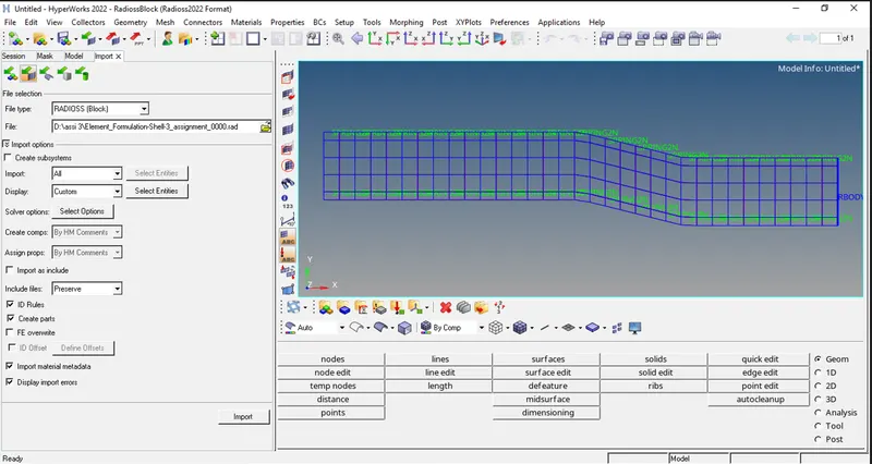
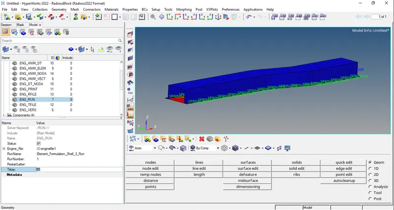
- Now, edit the file. For that, go to the cards folder and edit the ENG_RUN. Change the run time to 55 ms in Tstop.
- Change the run time to 55 ms in Tstop.
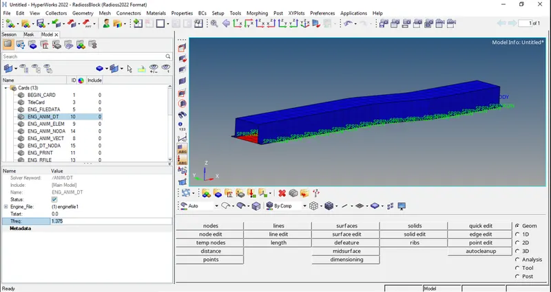
Change the number of animation steps during simulation to a minimum of 25 and a maximum of 60. So, we put 45 animation steps.
Frequency = 1/time
f = 1/t
Put the value in above equation,
f = 1/55
f = 0.01818 Hz
Multiply frequency by 40
f = 1/0.01818 × 40
f = 1.375 Hz
- In model tree, under CARDS collector, ENG_ANIM_DT card have a Tfreq of 1.0, which is changed to 1.375.
- After that, go to analysis and select radios.
- Upload .rad file and put -nt 4 in options, then press Radioss.
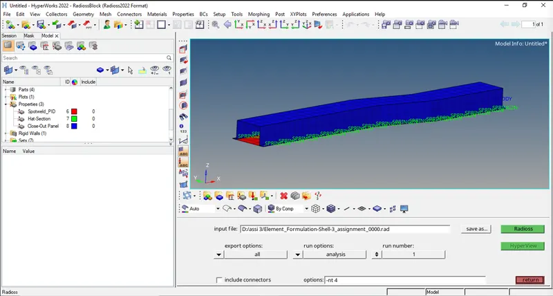
- Wait for a minute to complete the entire procedure.
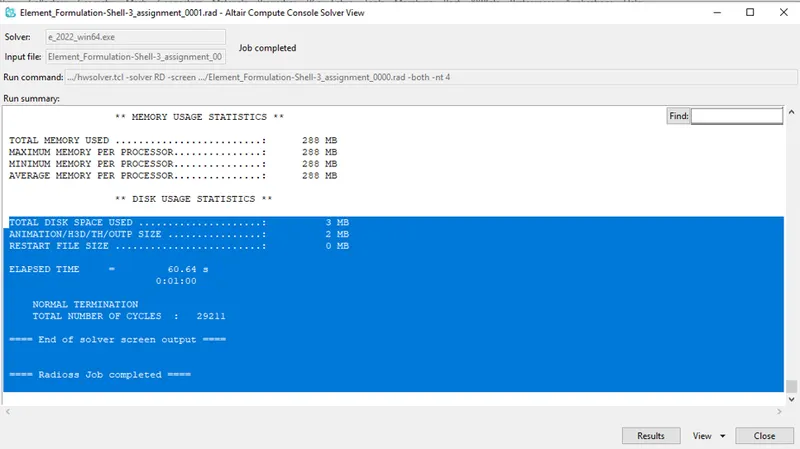
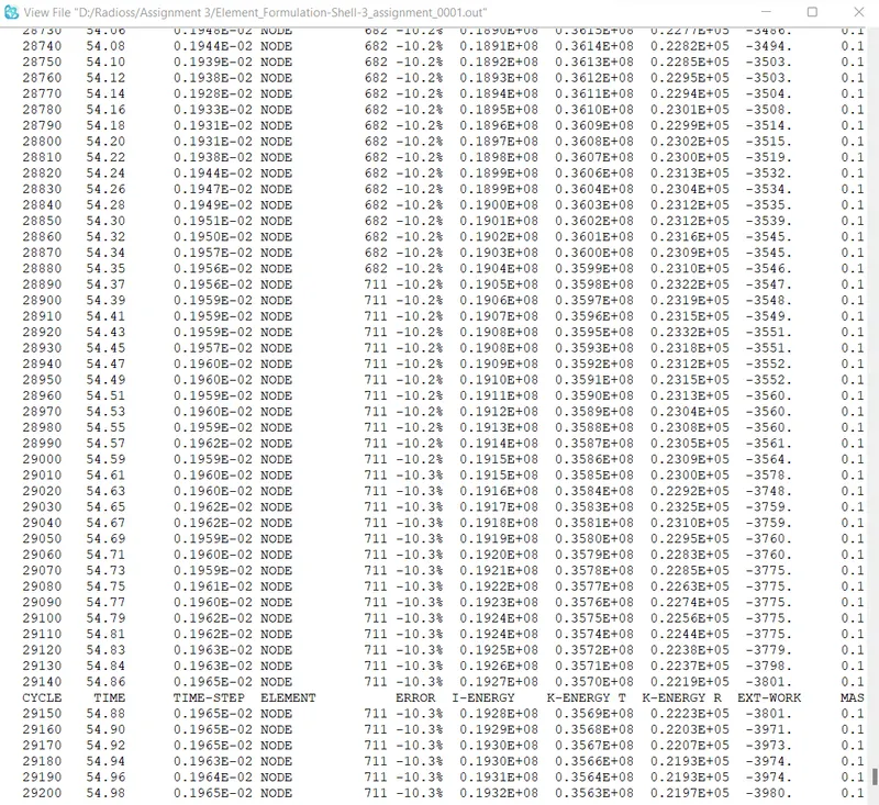
- The Energy error range is between -15% to +5%, and we obtain -10.3% which is an acceptable range.
- Now, the job is completed. Press Result.
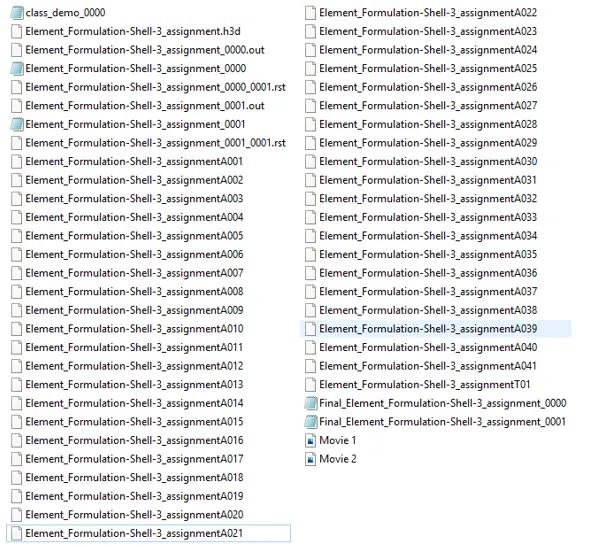
All Files:-
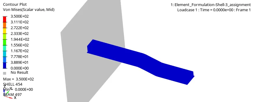
Von-Mises Stress-
Hourglass Energy-
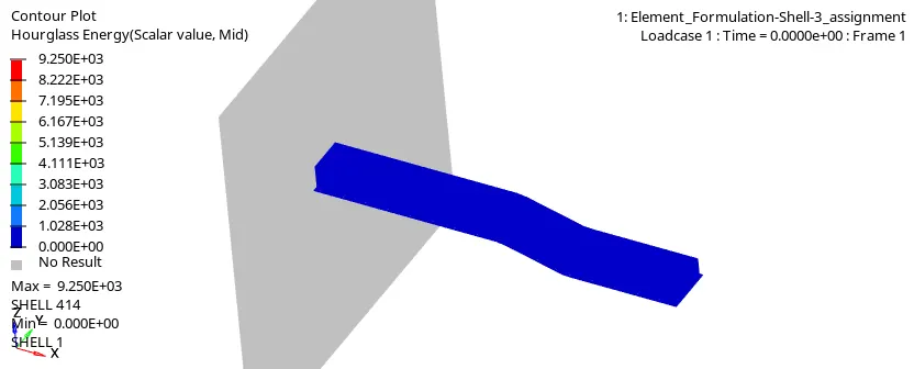
- Hourglass energy is range between Min. -2.758E+01 to Max. +2.758E+04. As shown in the above animation.
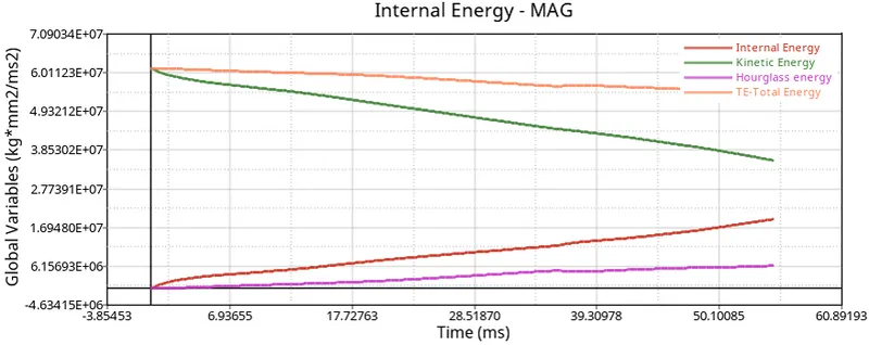
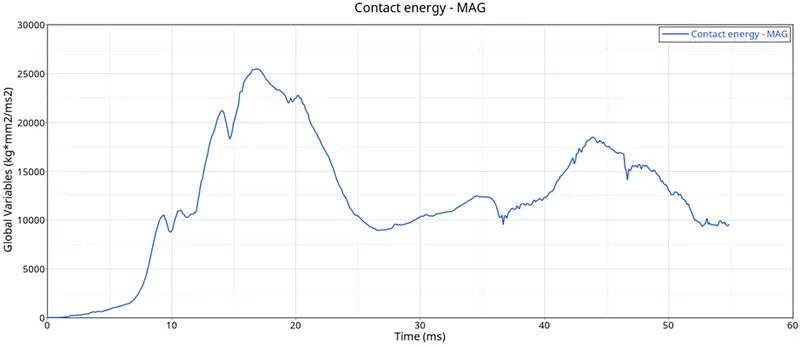
- Now, open the Hypergraph 2D to view the graph and open the assignmentT01 file.
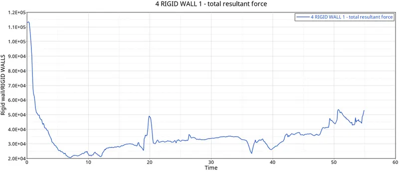
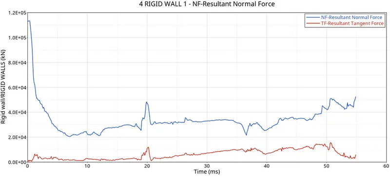
CASE 2
In case 2 assign the Recommended properties:
|
Parameters |
Comment |
|
|
Ishell =24 |
QEPH 4 nodes shells are the best combination of cost and accuracy. |
|
|
Ismstr=2 |
Full geometric nonlinearities (default)with possible small strain formulation activation in RADIOSS Engine. |
|
|
Ish3n=2 |
Standard 3 noded shell (C0) with modification for large rotation(default) |
|
|
N=5 |
The number of integration points is set to 5 for accuracy bending. |
|
|
Ithick=1 |
Thickness change is taken into account for accuracy. |
|
|
Iplas=1 |
Iterative plasticity for good accuracy. |
Now, open the property and put all the above-given values.
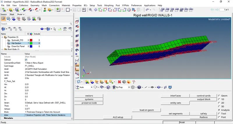
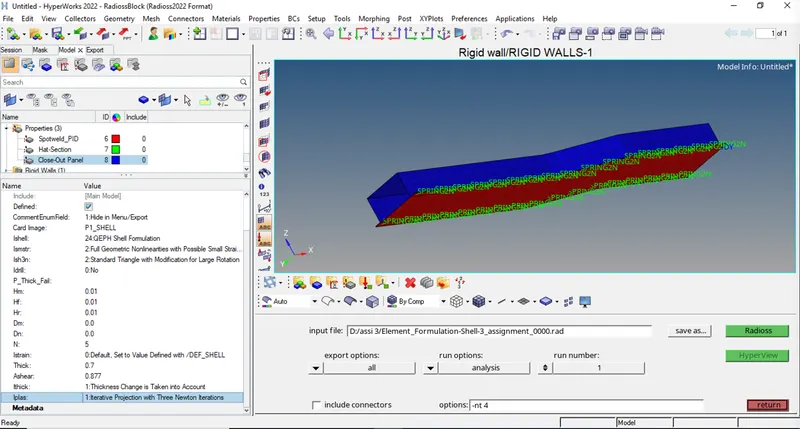
After that, go to analysis and select radios.
Upload .rad file and put -nt 4 in options, then press Radioss.
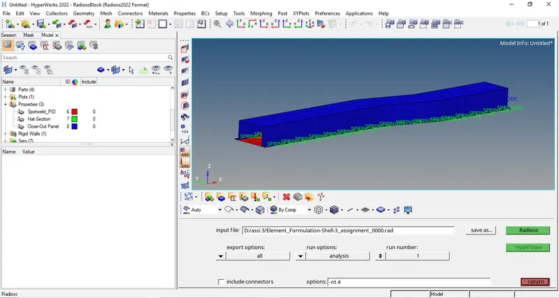
Wait for a minute to complete the entire procedure.
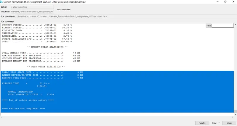
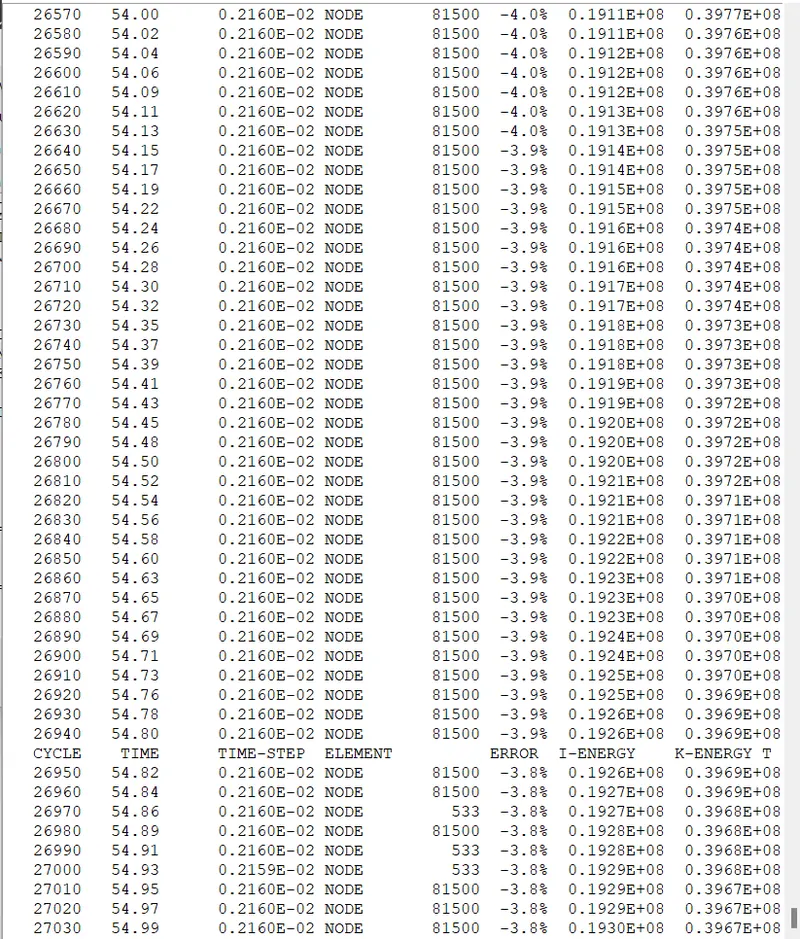
- The Energy error range is between -15% to +5%, and we obtain -3.8% which is an acceptable range.
- Now, the job is completed. Press Result.
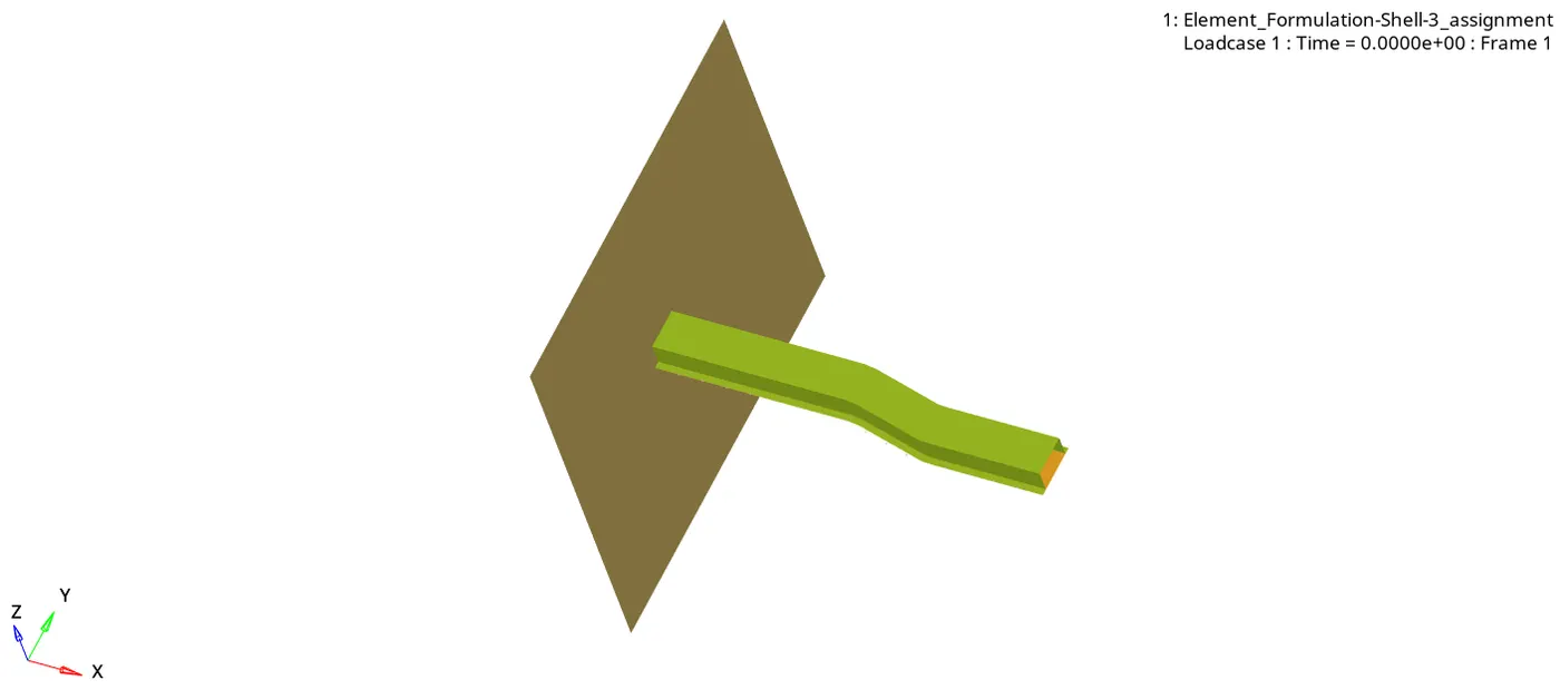
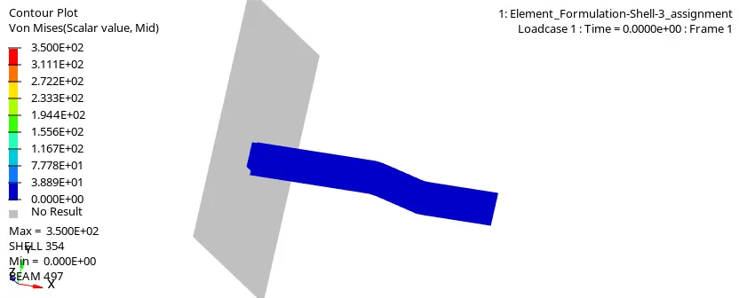
Von-Mises Stress
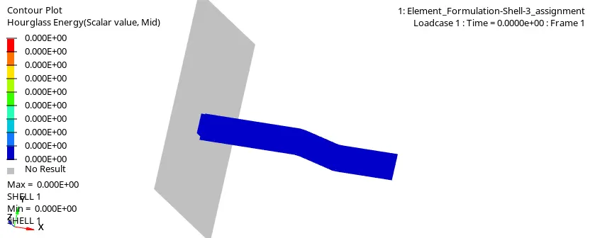
Hourglass Energy-
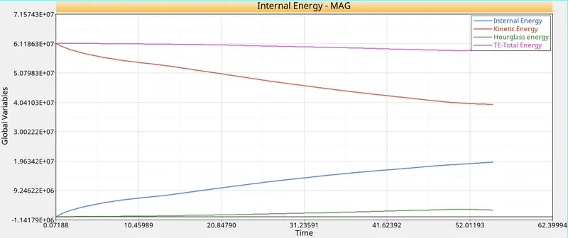
- File named Element_Formulation-Shell-3_assignmentT01 is opened.
- Specified energies are plotted against time on the same plot as shown below:
Comparison of CASE 1 & CASE 2
|
Parameters |
CASE 1 |
CASE 2 |
|
1. Energy Error |
-10.3% |
-3.8% |
|
2. Kinetic Energy |
0.3563E+08 |
0.3967E+08 |
|
3. Internal Energy |
0.1932E+08 |
0.1932E+08 |
|
4. Hourglass Energy |
Min. -2.871E+01 Max. 2.284E+04 |
Min. -9.957E+01 Max. 3.653E+04 |
|
5. Mass Error |
0.1659E-03 |
0.1659E-03 |
|
6. Von mises stress |
3.500E+02 |
3.500E+02 |
Learning Outcomes: -
- We learnt about how to analyze the file using radioss.
- We learnt about how the energy error and hourglass energy change the model values.
- We learnt about how to perform animation with different methods like Von mises and Hourglass energy in contour mode.
- Also, we learn about how to plot the graph of internal energy, kinetic energy, hourglass energy, total energy, contact energy, and time step.
Conclusion: -
In this project, we check the difference between CASE 1 & CASE 2 how the energy error and hourglass energy affect the model with the same run time and animation steps.