Week-6 Calculate the Stretch Ratio by comparing the ELFORM (-2,-1,1,2) with Ogden_Material Model.
Aim-
Given is a Ogden material card which is hyperelastic (rubber). Create a 10x10x10mm solid mesh and run a pure tensile run on it with stretch ratio of 5. Compare different element formulations of solids 1,-1,2,-2 and plot engineering stress vs stretch values.
Explanation-
Since this simulation is happening at a really slow pace (quasi static) the inertial effects can be neglected we can consider implicit for the analysis.
Since this a hyperelastic material even though we are running it in implicit , we need steps and iterations to achieve the equilibruim.
Element formulations used are 1,-1,2,-2 for solids.
ELFORM 1 - underintegrated constant stress ; needs hourglass stabilisation; efficient and accurate
ELFORM 2 - Reduced integrated ; no hour glass stabilisation needed; slower than ELFORM 1; shear locking can occur
ELFORM(-1 )- Similiar to ELFORM 2 , but shearlocking is accounted for; efficient formulation (CPU time)
ELFORM (-2) - Similiar to -1 , more accurate, more computational cost.
Procedure-
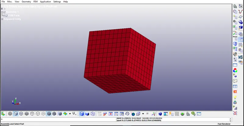
- We have to open the given LS-Dyna keyword (.k file) file in LS-PrePost, using option File>Open>LS-Dyna Keyword File as shown in below snap.
Step 1:- Import:
- Import the keyword file using LS - Prepost.
Step 2:- Create Material and Section Card:
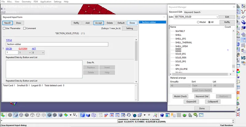
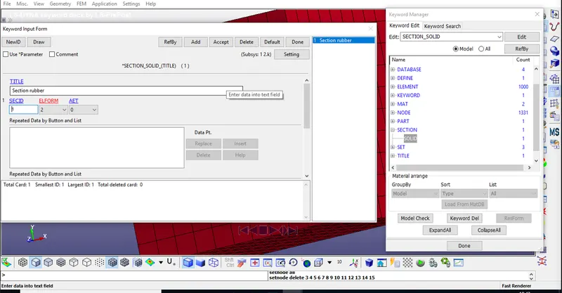
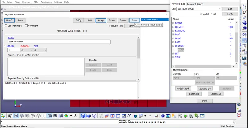
- First we will start with section card, to create section card from keyword>>all>>section>>solid>>here we will input id, elform type as shown below.
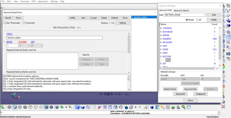
- As per given cases we have to change ELFORM as 1, -1,2 & -2, accordingly as shown in above snap or we can do it form .k file after saving it.
- Now we will check the MAT card given to us.
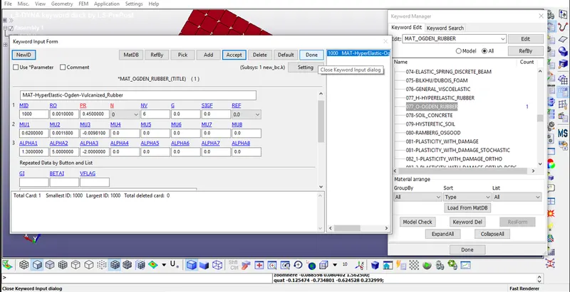
ELFORM 1
ELFORM -1
ELFORM 2
ELFORM -2
- Finally we have to assign the section and material to the part.
Step 3:- Creat Baundary Conditions with some NSet .
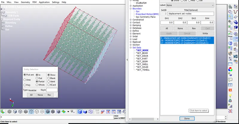
- Here we will fix the Bottom of the Cube and give the motion to the set of nodes on the Upper face.
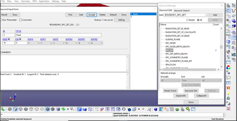
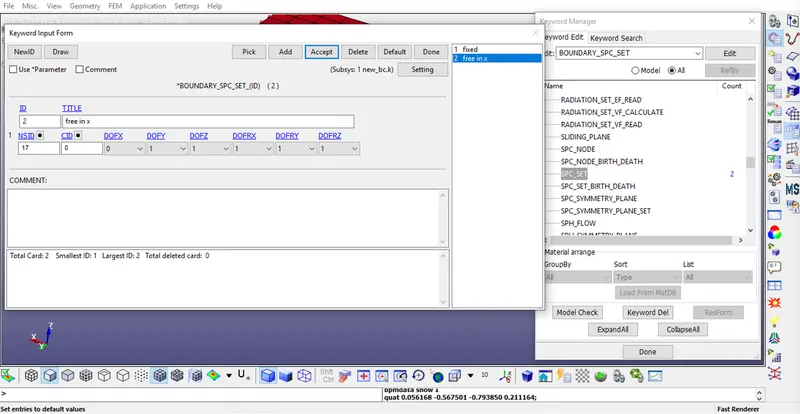
- To fix the Bottom face, we will use different set of nodes and using single point constraint boundary, we can allow or constraint the nodes with different degrees of freedom.
- Boundary conditions using single point constrained for different set of nodes will be as given below:
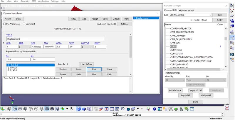
CREAT CURVE FOR DISPLACMENT IN Z DIRECTION.
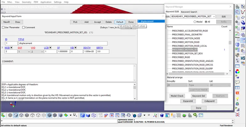
- To apply the tensile load in Z-Direction to the cube, we have to give the motion to the set of node on the upper face of the cube.
We know that Stretch = 1 + Engg strain
=> 5 = 1 + (change in length / 10)
=> Displacement(change in length) = 40mm
- As shown in above image, we have given DOF = 3 , to allow translation in Z-Direction translation
- VAD = 2 is given for Displacement.
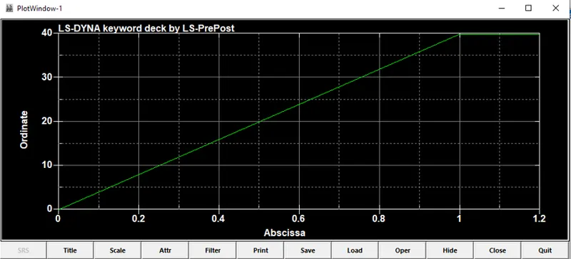
- We will define curve for displacement is given below, displacement is linearly applied at constat rate.
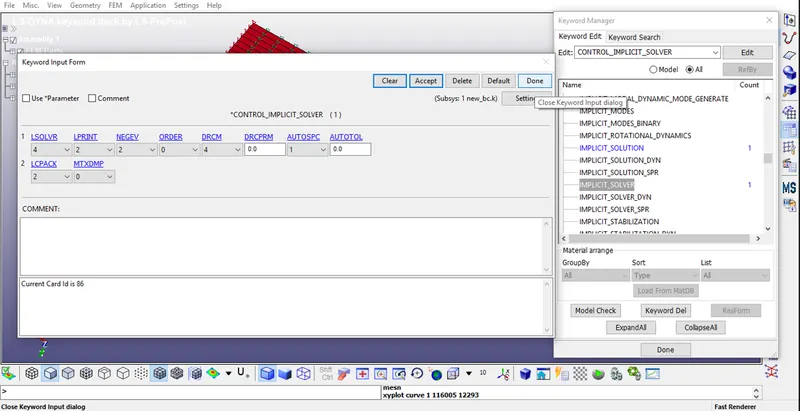
Step 4:- Creat control energy, implicit auto,implicit genral,implicit solutiom ,implicit solve.
- In *CONTOL_IMPLICIT_GENERAL, IMFLAG =1 is given to activate the implicit analysis method and initial Time step value is given as 0.1.
- In *CONTROL_IMPLICIT_AUTO, values of DTMIN and DTMAX are not defined, so that the solver can change the time step size as needed automatically.
- In CONTROL_TERINATION, ENDTIM is set to 10. Here termination does not represent the time but gives the value at which step the analysis will end.
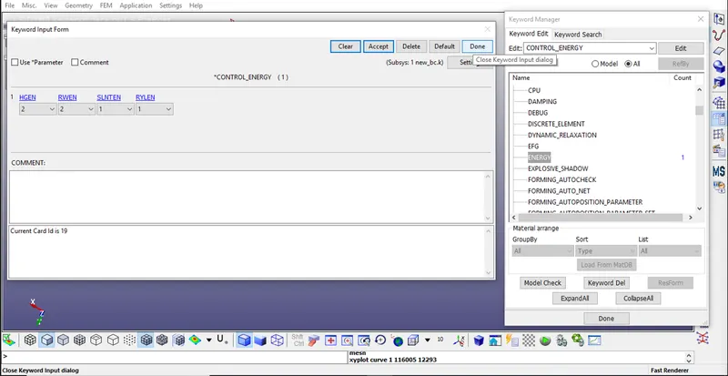
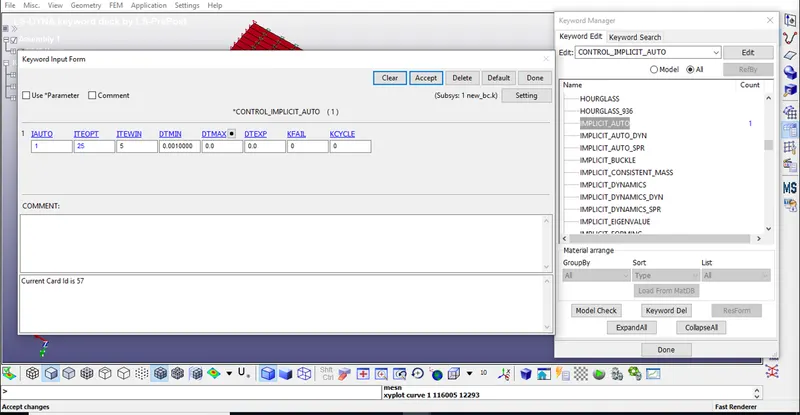
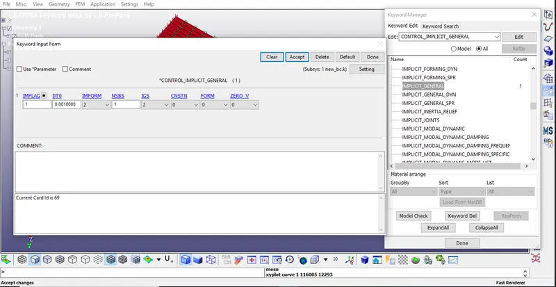
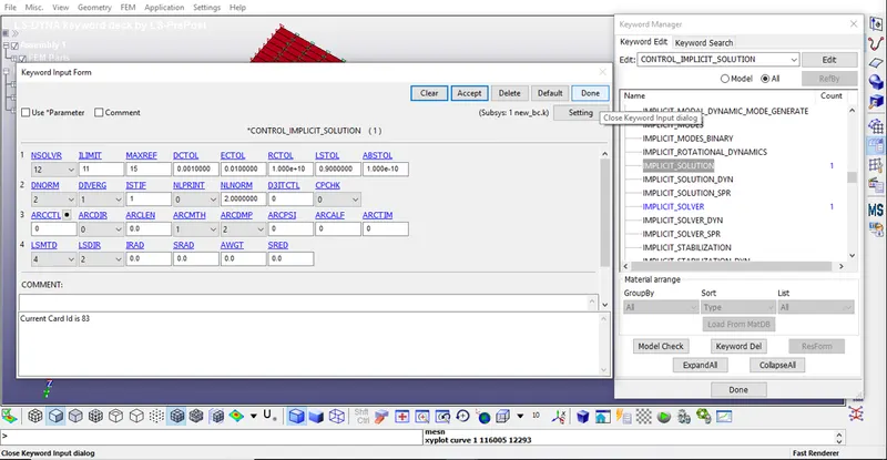
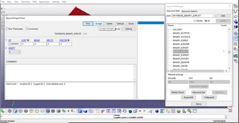
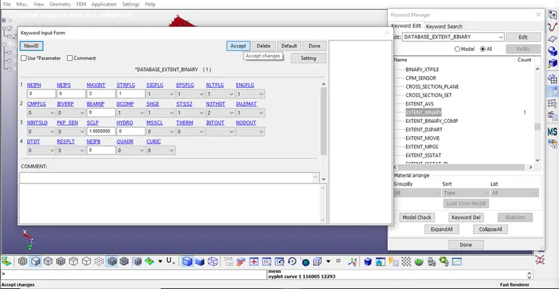
Step 5:- Creat Database for output like Binary D3Plot ,ASCII.
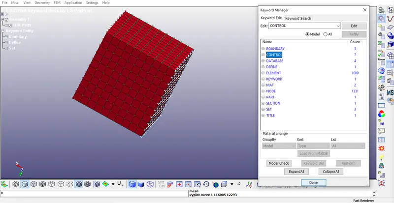
CHECK THE MODEL
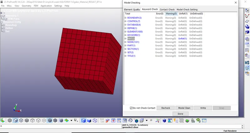
- Since there is no error we can proceed further to save and run the keyword file ONE BY ONE.
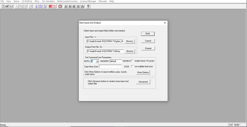
- All simulations ended with Normal Termination. Therefore, all the models are simulated successfully.
- Now we can open this files one by one using LS-post processor.
Results & Plots-
Effective stresses
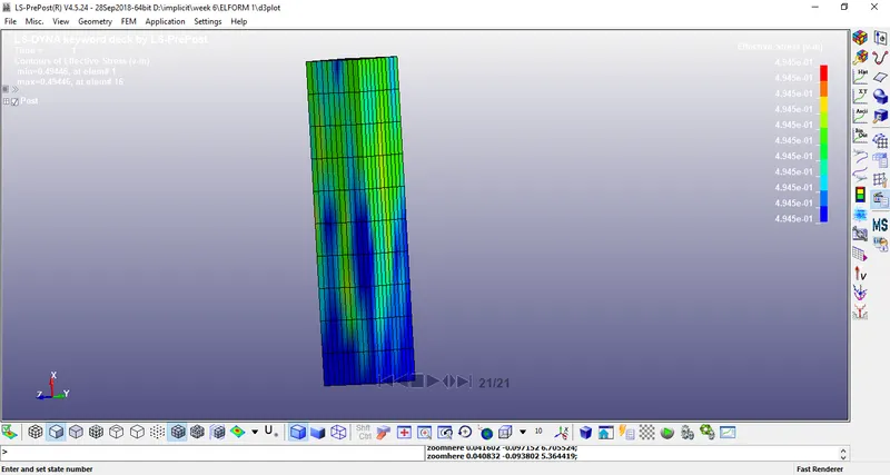
ELEMENT FORMULATION 1:-

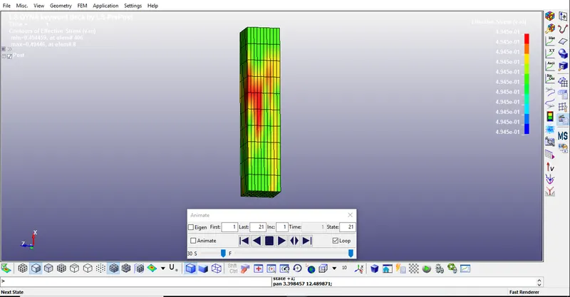
ELEMENT FORMULATION -1:-
ELEMENT FORMULATION 2:-
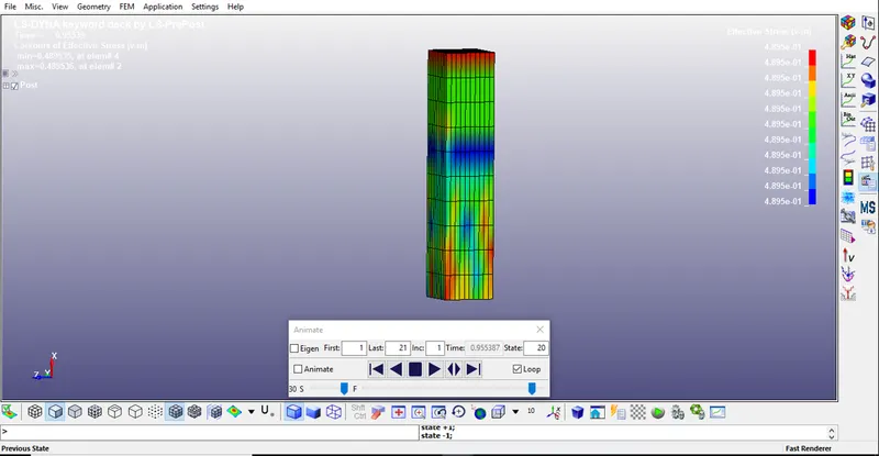
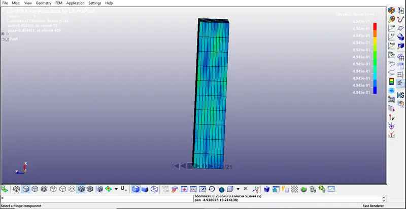
ELEMENT FORMULATION -2:-
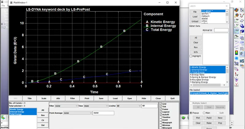
Comparison:
- Plots obtained from the simulation results, we can observe the Stress and Strain results are same for different solid element formulations.
- We can observe same stretch ratio for all different element formulations.
- But we can see the distribution of stress over the length of the cube is in different manner while stretching. This is due to different behavior of element formulations.