Assignment 6-Frontal Crash Simulation Challenge
Aim:
To perform a Frontal crash simulation challenge. Following steps should be followed
- Create an appropriate interface, friction 0.2, and recommended parameters.
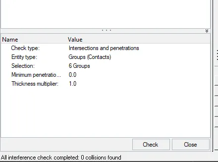
- Make sure of no penetrations and intersections.
- Correct rigid bodies if any issues.
- Create a rigid wall with friction 0.1.
- Compare the model weight with the full-scale 300k nodes model and use added masses to reach a target weight of 700kg while getting CG about the required range
- Initial velocity 35 mph.
- Use a model checker to ensure good quality.
- Time-step :0.5 to 0.1 microseconds.
- Run 80 ms.
- Sectional force in the rails at the location of indicated node 174247.
- The axial force received on the rails from the bumper.
- Shotgun cross-sectional forces.
- A pillar cross-section.
- Acceleration curve received on the accelerometer at base of B pillar (on B pillar rocker).
- Intrusions on the dash wall 66695,66244.
PREREQUISITES:--

A frontal crash is the most common type of crash resulting in fatalities. Major strides have been made in frontal protection, thanks in large part to the crash test program that the National Highway Traffic Safety Administration (NHTSA) began in the late 1970s and the crashworthiness evaluations that IIHS began in 1995.
IIHS conducts three different frontal crash tests: a moderate overlap test (formerly known as the frontal offset test), a driver-side small overlap test and a passenger-side small overlap test.
A frontal crash is the most common type of crash resulting in fatalities. Major strides have been made in frontal protection, thanks in large part to the crash test program that the National Highway Traffic Safety Administration (NHTSA) began in the late 1970s and the crashworthiness evaluations that IIHS began in 1995.
IIHS conducts three different frontal crash tests: a moderate overlap test (formerly known as the frontal offset test), a driver-side small overlap test and a passenger-side small overlap test.
PROCEDURE:--
STEP 1—CHECK COG POINT
- Initially changing the CENTRE OF GRAVITY by using CRASH application
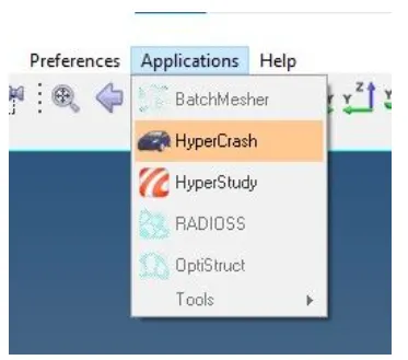
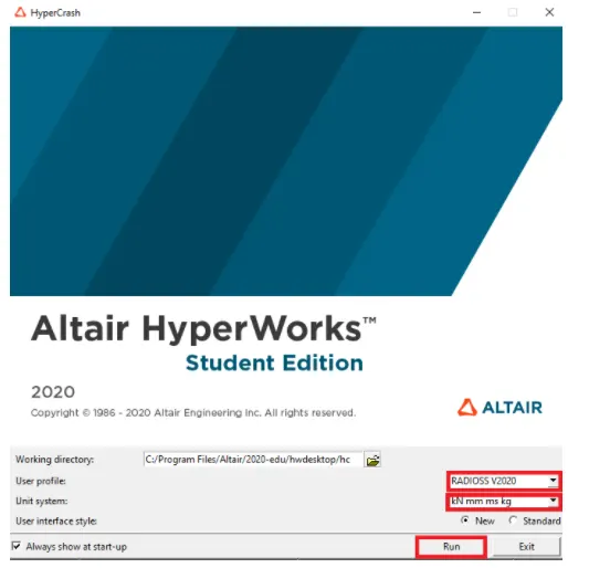
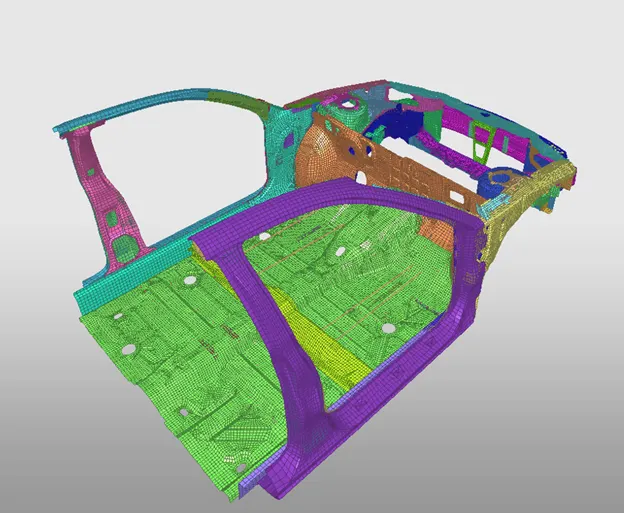
- After changing the units, Import the files in crash.
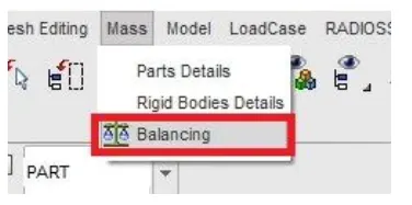
- To change the center of gravity go to MASS-BALANCING
- View the center of gravity
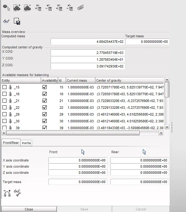
- Initial position of COG is
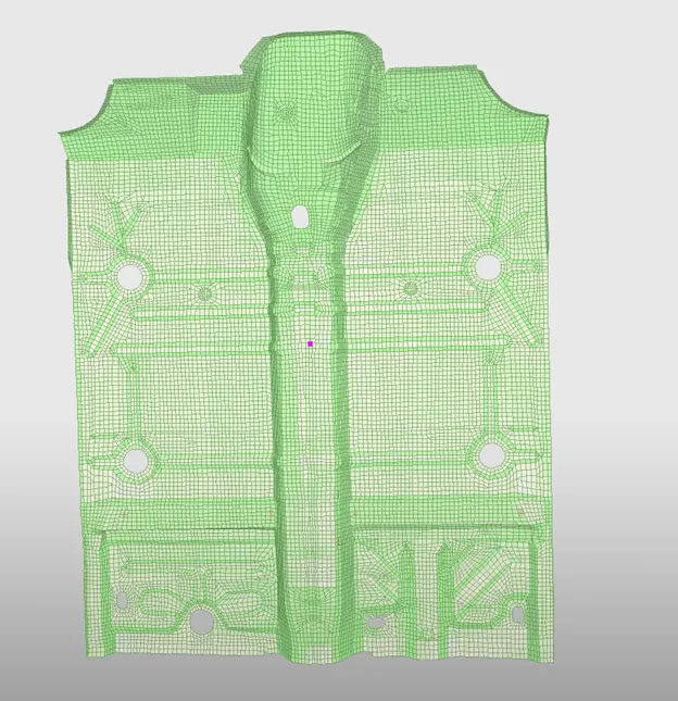
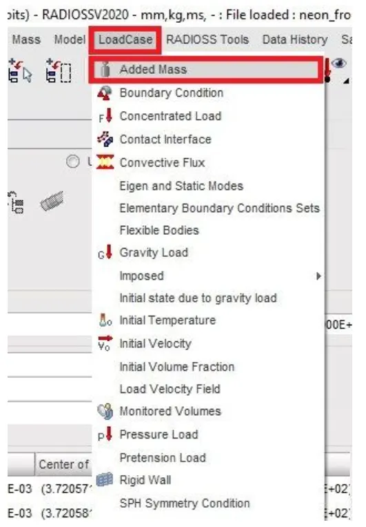
- Now mass should be added in all the passenger seat of 70 kg. To add go to LOAD CASE—ADDED MASS—CREAT NEW—TYPE1

- To select the nodes ADD/REMOVE NODES IN THE GRAPHICAL AREA
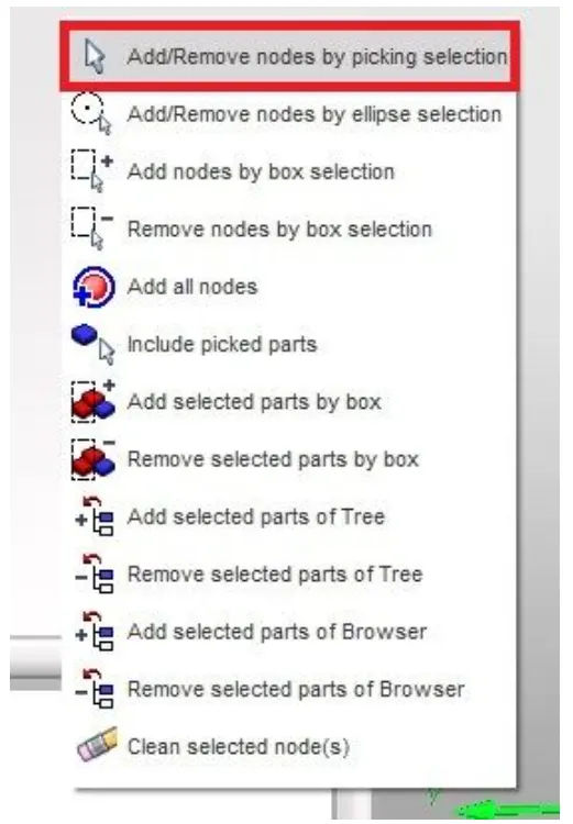
- After this select the nodes
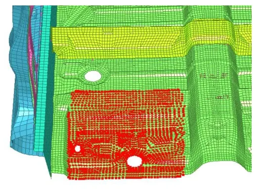
- Hit yes and save the changes
- Now do the same for all the three remaining seats.
- After do the same. COG will come on center
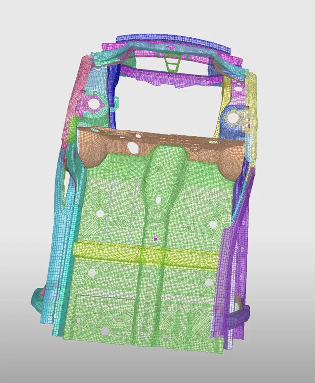
STEP 2—PENETRATION CHECK
- Now save the model and open the same model in Hypermesh
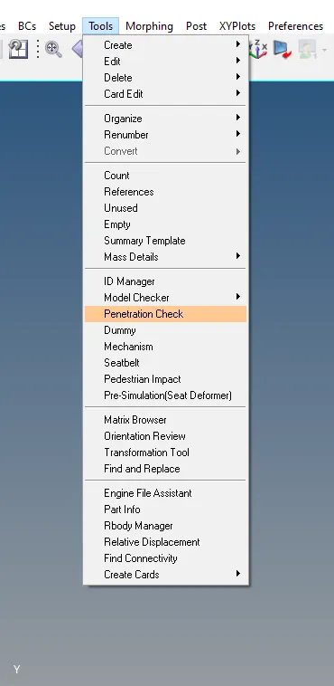
- Now check for penetration TOOLS—PENETRATION CHECK.
STEP 3—CREATING INTERFACE
- Create TYPE 7 interface using recommended parameters
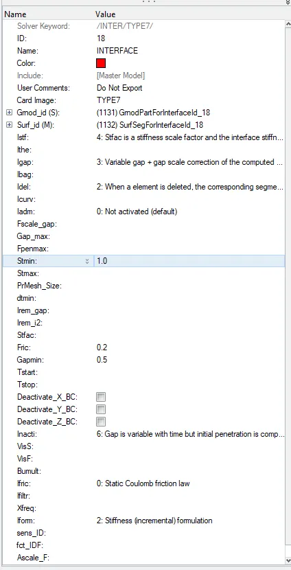
STEP 4—CREAT RIGID WALL
- Go to SOLVER DECK—RIGHTCLICK CHOOSE RWALL—PLANE
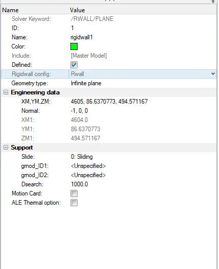
THERE SHOULD BE 5-10MM DISTANCE BETWEEN COMPONENT AND RIGID WALL.
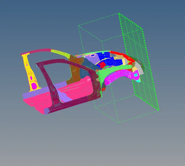
- FRICTION value should be 0.1
STEP 4—APPLY BOUNDARY CINDITION
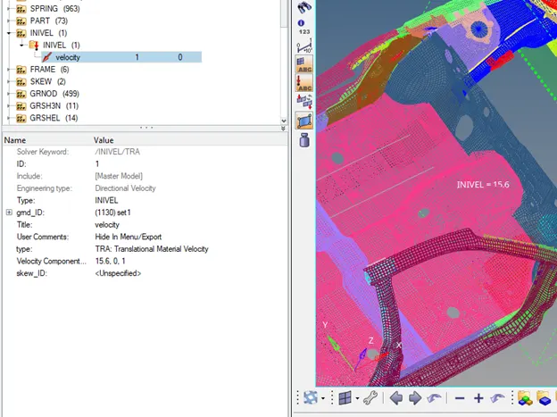
- INITIAL VELOCITY/INIVEL
- SOLVER BROSER—RIGHTCLICK—BOUNDARY CONDITION—INIVEL
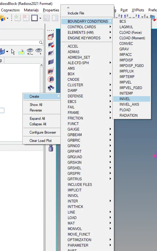
- Change the 35mph to mps that will be equals to 15.6
STEP 5—CREATE SECTION
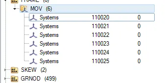
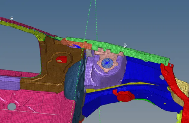
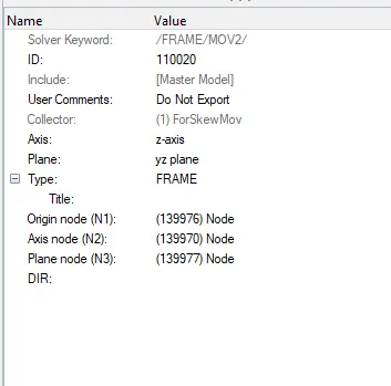
- Before section we have to define the moving frame
To define that go to SOLVER DECK—RIGHTCLICK—FRAME—MOVE
WE HAVE TO CREAT FRAME ON
- A PILLAR
- SHORTGUN
- RAIL
ON BOTH SIDE THAT IS LEFT AS WELL RIGHT SIDE. SO THERE WILL BE 6 FRAME
STEP 6—CREAT SECTION FOR THE FRAME
- To create section go to SOLVERDECK—RIGHTCLICK—SECT—SECT
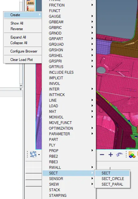
- Define the frame_id & grshel_id
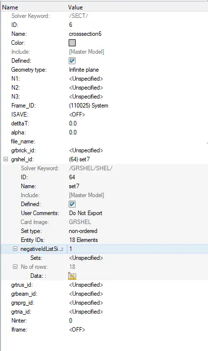
To create grshell_id right click on that and hit create now choose the elements nearby of the frame
THERE WILL BE 6 SECTION FOR THE 6 FRAME
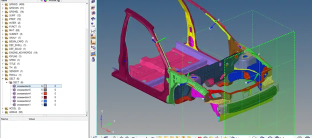
STEP 7—CREAT ACCELEROMETER
- To create accelerometer go to SOLVERDECK—RIGHTCLICK—ACCELEROMETER
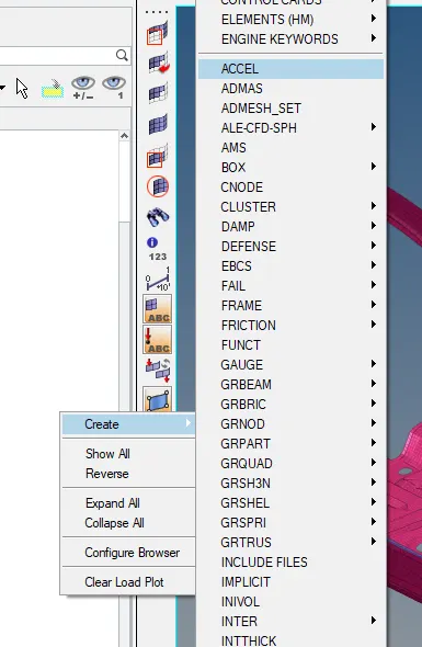
- SPECIGY THE NODE ON THE FLOOR.
- AND DO IT DAME WAY FOR OTHER SIDE AS WELL
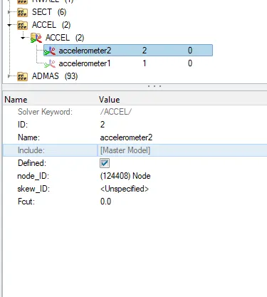
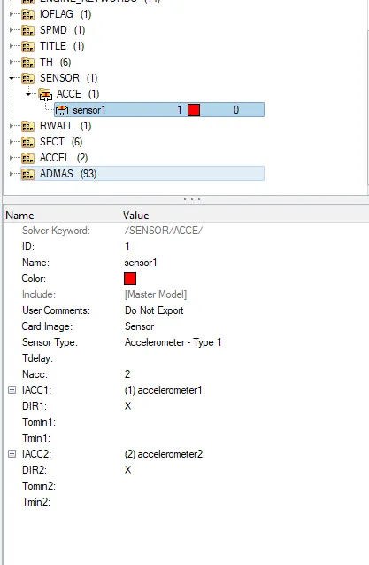
- After this we have to assign the sensor to the accelerometer
SOLVERDECK—RIGHCLICK—SENSOR—ACCEL
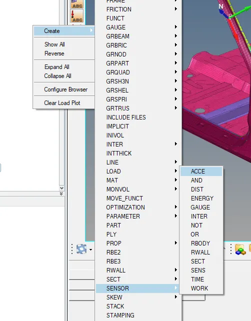
- Now define the accelerometer for both side floor
STEP 8—CREATE INTRUSION
- To create intrusion go to MESH—CREATE—1D SPRING.
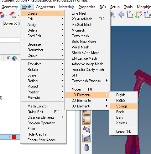
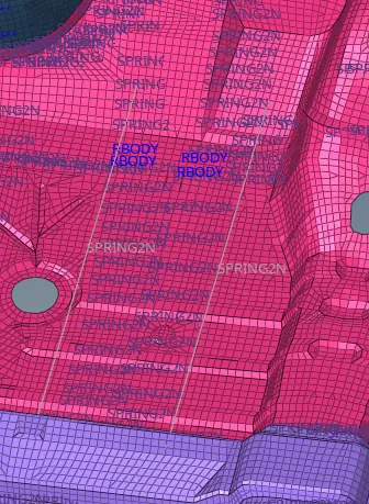
- Now define the property for the spring component. And assign its component also

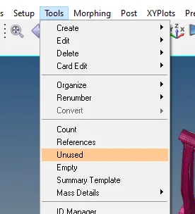
STEP 9—DELETE THE UNSED AND EMPTY FILES FROM CRASH
- For this go to TOOLS—UNUSED—SELECT AND DELETE.
- Also delete the empty card as well
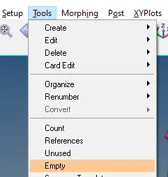
THIS MEANS THERE IS NO EMPTY AND UNSED CARD IN THE MODEL WHICH MAY CAUSE EEROR
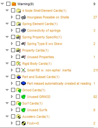
STEP 10—RIUN THE MODEL CHECKER IN CRASH
- Import the model in crash application.
- Now go to QUALITY—MODEL CHECKER—RUN
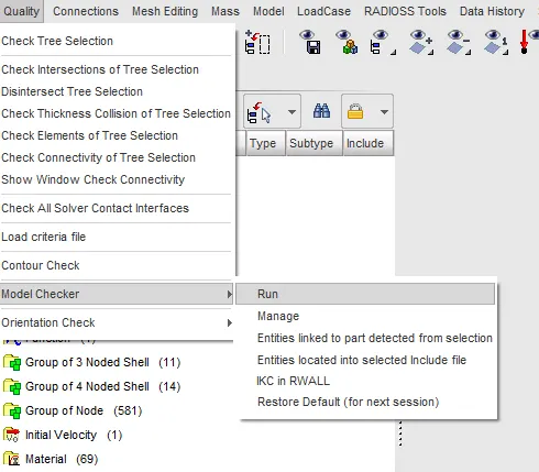
- It is best practice to do so that model will be very clean.
- But there are some genuine warning & those are totally acceptable.
STEP 11—RUN THE SIMUALTION
- Import the model in Hypermesh
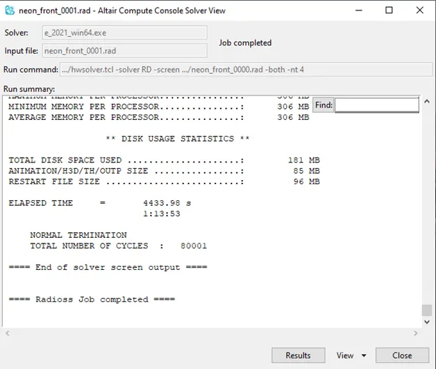
- Go to ANALAYSIS—RADIOSS
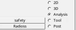
- Specify the location and mention –nt 4 in option

STEP 12—DO THE POST PROCESSING
- Click on result.
- Import .h3d file the animation
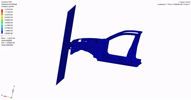
This is the von misses displacement animation
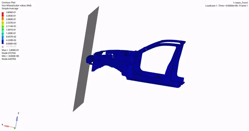
This is the displacement deformation aninmation
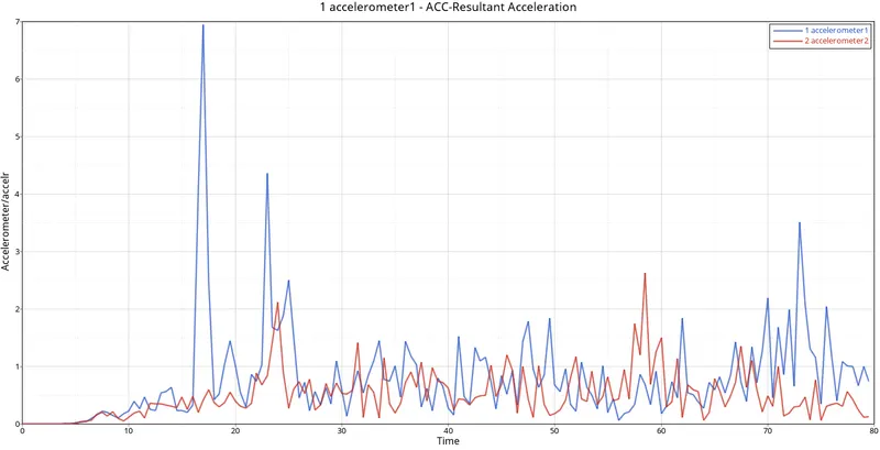
- Import .T01 file to plot the graph
- Graph of total acceleration force defined both side of the floor. It reaches peak around 6.8 m/s. curves follows the zig zag pattern.
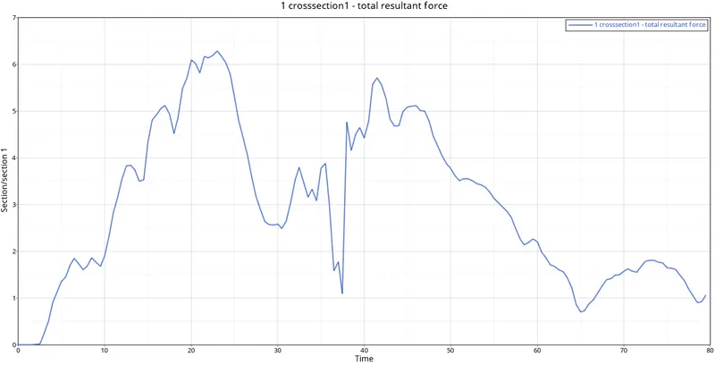
43. Obtained graph of TOTAL RESULTANT FORCE RIGHT-HAND SHORTGUN. It reaches a PEAK at 6.3kN. Curves follow zig zag manner
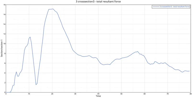
44. Obtained graph of TOTAL RESULTANT FORCE ON RIGHT-HAND RAIL. It reaches PEAK on 16.56KN. Curve start after some time then increases, reaches peak and then starts decreasing
45. Obtained graph of TOTAL RESULTANT FORCE ON RIGHT-HAND A PILLAR. It reaches PEAK on 6.75 KN. curves follow zig-zag manner and reaches peak after considerable time
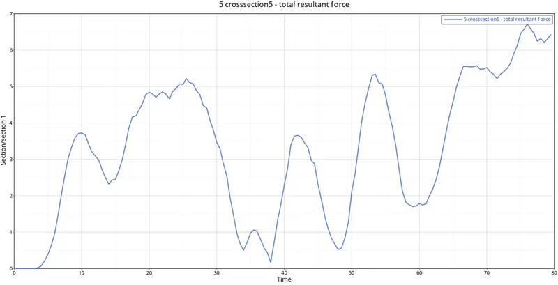
46. Obtained graph of TOTAL RESULTANT FORCE ON LEFT-HAND ON RAIL. It reaches PEAK on 35.1 KN. Curve start after small force and reaches peak and then becomes constant
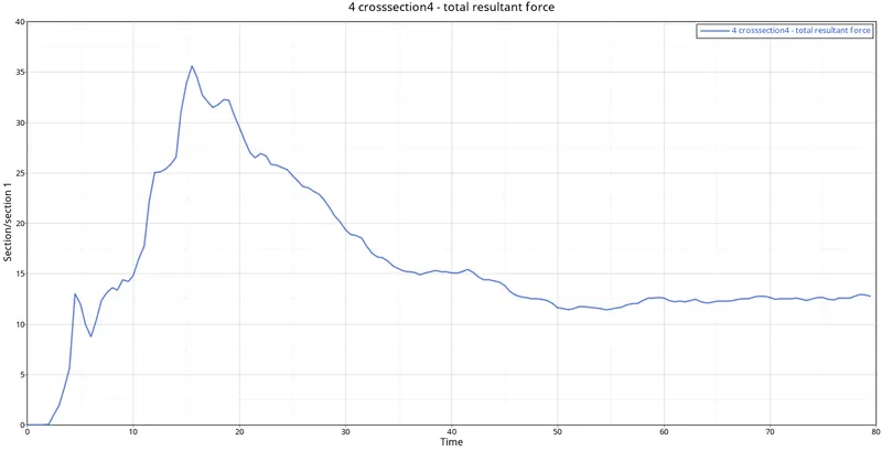
47. Obtained graph of TOTAL RESULTANT FORCE ON LEFT-HAND ON A PILLAR. It reaches PEAK on 35.6 KN. Curve starts after some force and then decreases and follow zig zag manner.
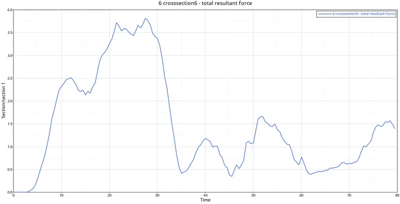
48. Obtained graph of TOTAL RESULTANT FORCE ON LEFT-HAND ON SHORTGUN. It reaches PEAK on 7.9 KN. Cuves follows same pattern as above
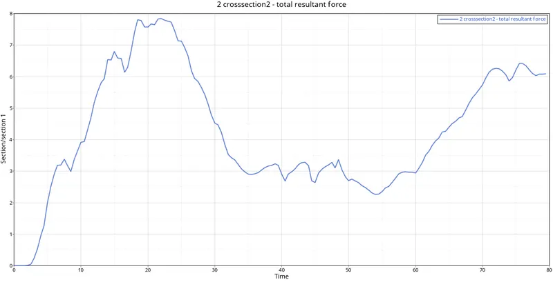
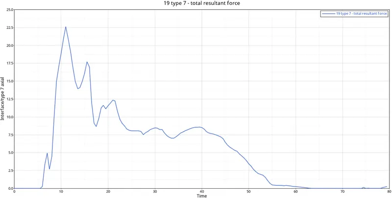
49. Obtained axial force of type 7. It reaches peak of 22.51 kn force. Curve first increses to pick and then starts decreasing.
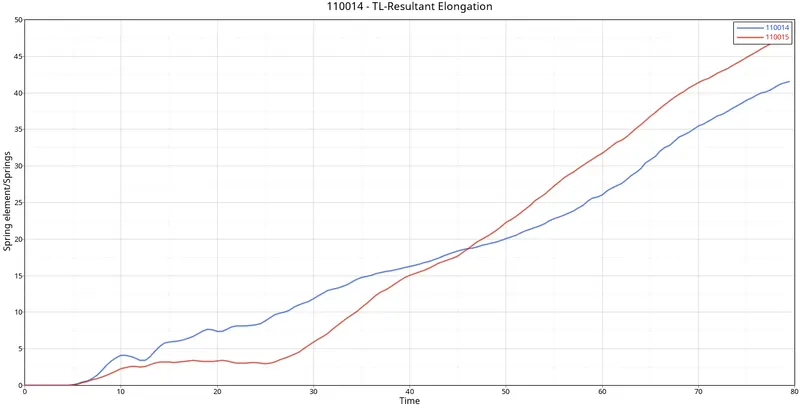
50. Obtained graph for both spring intrusion. Curve is increasing almost linearly and reaches peak on the 45.4 KN force
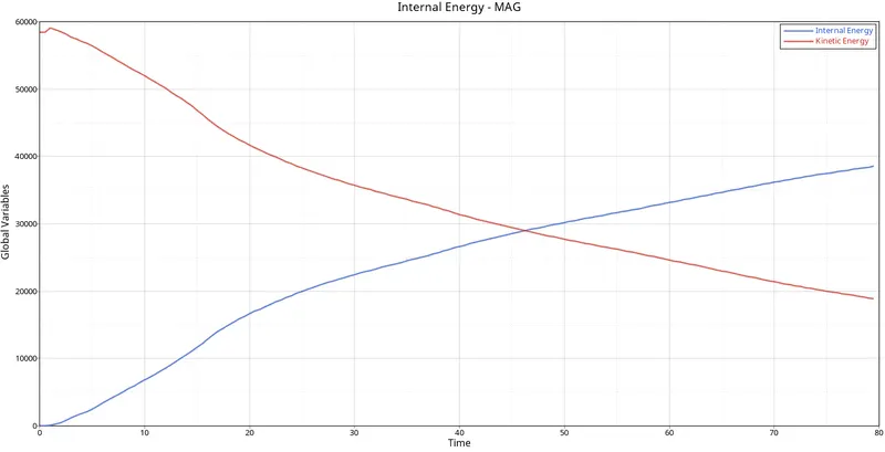
51. Obtained graph is for TOTAL INTERNAL ENERGY & TOTAL KINETIC ENERGY. Kinetic energy is decreasing and internal energy is increasing. And both forces intersect nearly at 40.6 sec
NOTE:-- ONE THING IS COMMON IN ALL THE GRAPH THAT DEFORMATION TAKES PLACE AFTER SMALL INTERVAL OF TIME AND REACHES PEAK ONCE IT COLLIDES WITH RIGID WALL.
CONCLUSION:--
1) Changed the COG
2) check for penetrartion
3) created new interface
4) created accelerometer on b pillar rocker
5) Assign the initial velocity
6) created type 7 contact at front to obtain axial force
7) created rigid wall
8) Finally plotted the graph with obtained result.