Week 3 - 2D meshing for sheet metal
AIM:--
For the given Hood model, Take the mid surface for all the components after checking the geometrical errors and mesh the mid surface with the given element Quality criteria.
PROCEDURE:--
1) First import the model in the appropriate format.
2) Then visualize the model properly.
3) After visualizing the model, you must have got an idea of how to do geometry cleanup.
4) In ANSA, There are three types of CONS/Lines
- SINGLE CONS -- 'Single' are the CONS that lie on one Face only (free edges) and it is represented by RED lines.
- DOUBLE CONS -- 'Double' are called the CONS that lie on the common boundary of two faces, which are topologically connected and it is represented by YELLOW line.
- TRIPLE CONS -- In geometry, 'Triple' are the CONS that are shared from three or more faces. In FE mesh 'Triple' are the common edges of three or more shells and it is represented by the CYAN line.
5) Check for Orientation of Model.Basically its function sets a uniform orientation direction to all visible Faces according to the orientation of the majority of the Faces. The mesh elements that will be generated, or those already existing, also obtain a uniform orientation.
YELLOW is negative.
GREY is positive.
6) After all of these check, there shouldn't be any CYAN colour in the model. There should be only YELLOW colour line in model.
7) To remove the CYAN colour.
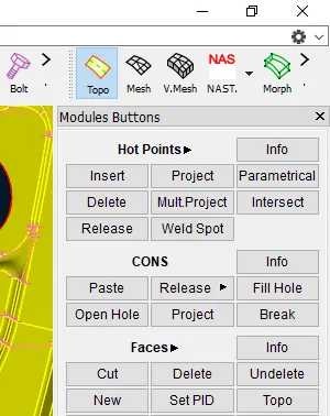
First we have to Release those CYAN colour lines from TOPO MODULE--HOT POINTS--RELEASE
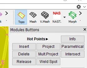
8) Then do the TOPO by selecting all nearby lines.
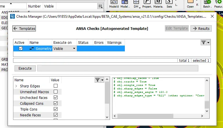
9) To identify all the geometry error we can use CHECK OPTION from TOOL bar.
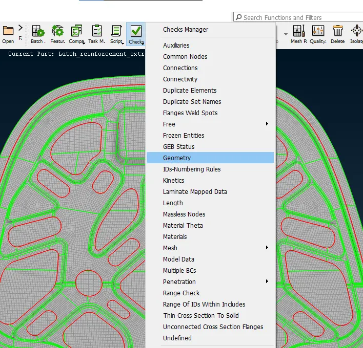
This tools is very helpful and it will identify all the error which are not visible also
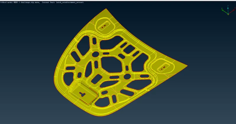
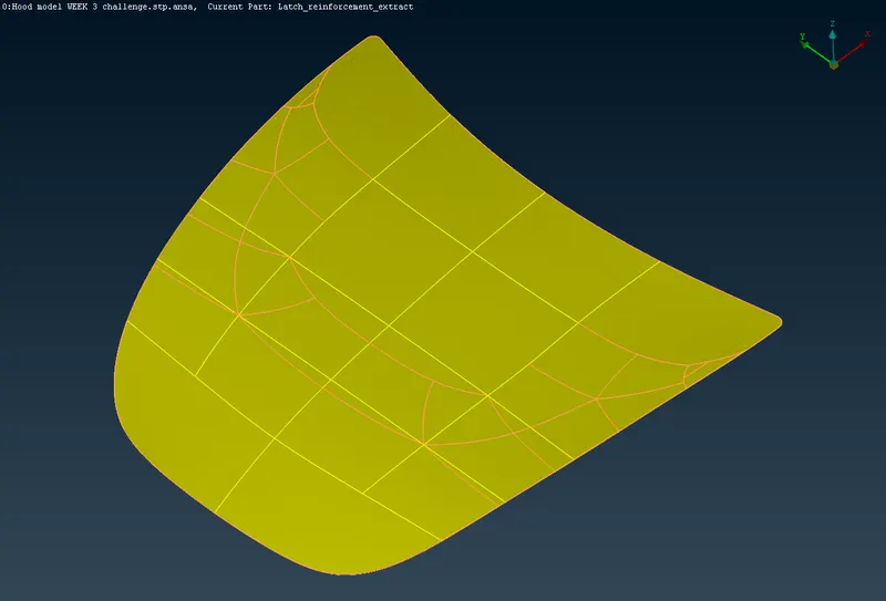
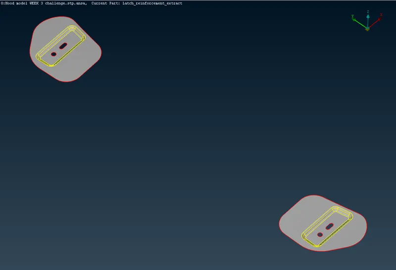
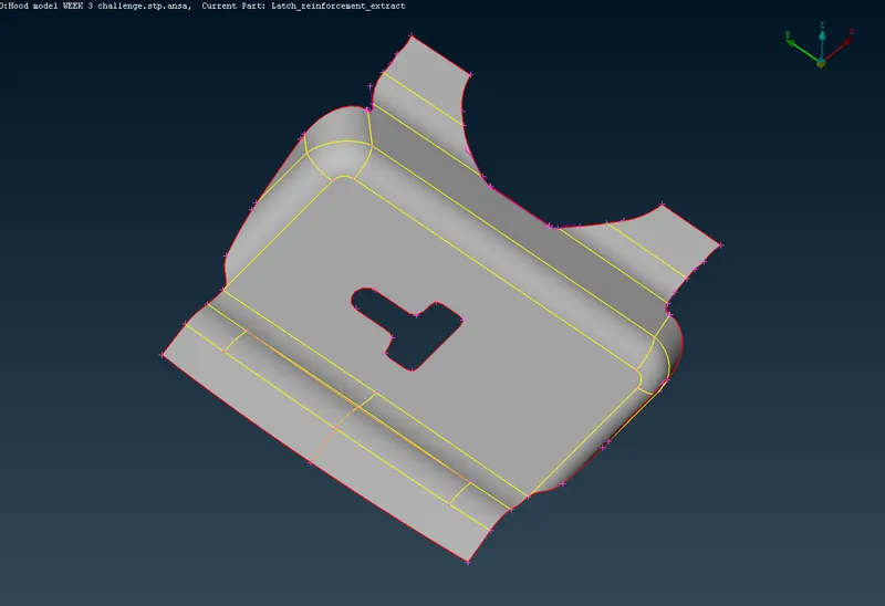
10) After geometry cleanup MODEL are
11) Now we have to start meshing
12) First we have to switch to MESH module
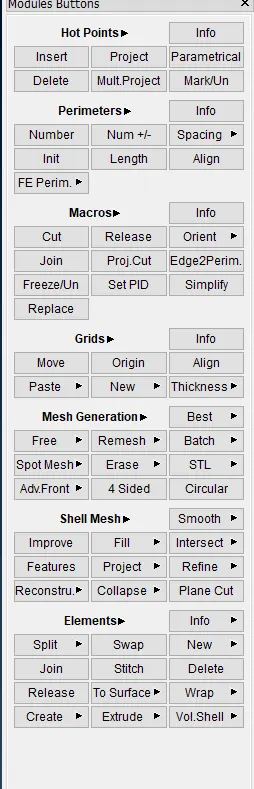
13) Creat criteria file setting by pressing F11 or BY using CRITERIA setting from UTILITY bar.
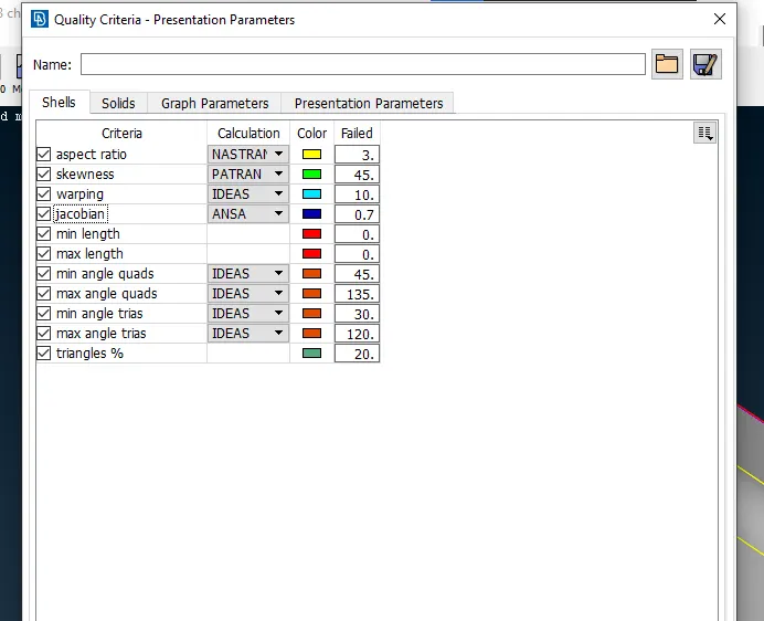
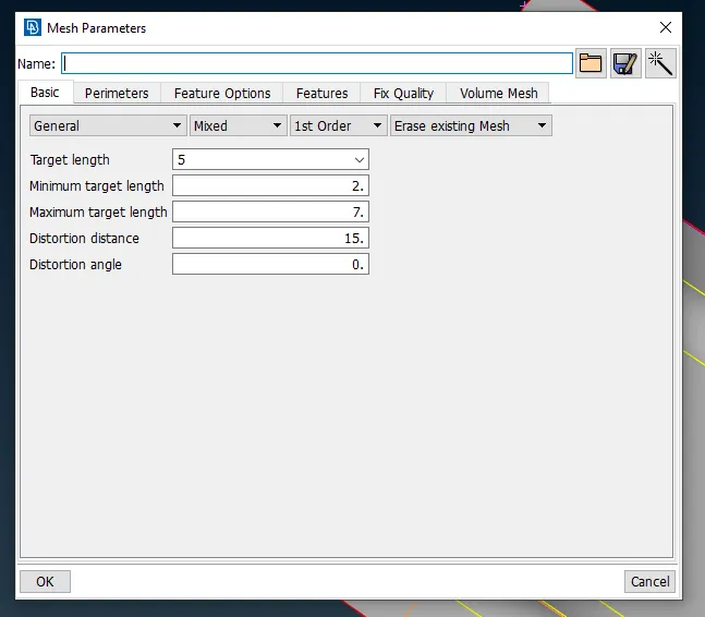
14) Now set the TYPE of element and SIZE of elements from MESH PARA in UTILITY bar.
Now we have to specify the LENGHT ( MESH MODULE--PARAMETER--LENGTH) for the perimeter and select the target lengh only. This function defines the element length on selected perimeter segments or macro areas. The element length may be explicitly declared or may be declared as a factor to be multiplied by the existing element length.
Before going to AUTOMESH option, check for geometry check always.
15) After this we Take the MID-SURFACE Manually or Automatically by TOPO MODULE--FACES--MID SURFACE
16) Now start meshing by selecting property one by one. We can switch to another property by pressing F12.
17) And there is many other VISIBILITY OPTION in ANSA.
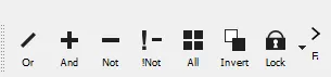
- OR -- Select to keep visible one or more entities by using the left mouse button or a box selection.
- AND -- Select one or more entities using the left mouse button or a box selection, in order to bring to visible any neighbour entities which may exist.
- NOT -- Select one or more entities using the left mouse button or with the box selection.
- !NOT -- Select entities that will remain visible. The selected entities temporarily (during selection) are excluded from the visible ones, but as soon as 'Enter' or the middle mouse is pressed (selections' termination) then they will only be the ones to remain visible in the graphics area.ALL -- Bring to visible all entities of the database. If the Lock flag button is active, then the function brings to visible only the entities that belong to the active locked view. If there are numerous stored locked views, then they will be displayed as a sub-options list of the All button.
- INVERT -- Invert the current view according to all entities of the database or invert the current view according to the last locked view (in case there are stored locked views).
18) After assigning the criteria setting now we have to specify the LENGTH. This function defines the element length on selected perimeter segments or macro areas. The element length may be explicitly declared or may be declared as a factor to be multiplied by the existing element length.
19) Measure the length between two-point and check if it is greater than the min length, otherwise, it will fail for the same criteria.
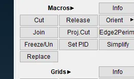
If there we can suppress that line and compromise some feature. For this, we can use the CUT option from the MACROS section.
20) Now we are done with everything, we can start meshing now.
21) We can use BEST option from the MESH module-- Mesh generation-- BEST
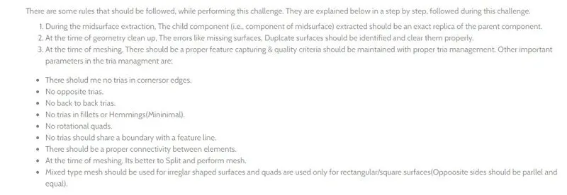
22) Now remove all the unwanted trias and while removing take care of all these points.
23) To Remove trias we can following tools
- SPLIT -- (MESH MODULE--ELEMENTS--SPLIT) This function splits quadrilateral and triangular shell elements into smaller ones. Element splitting is performed between selected nodes and/or inserted nodes along selected element edges. The function can be applied on individual or groups of shell elements in order to improve the mesh orientation, reduce the number of triangles, or refine locally or globally the mesh of a part. Refer to ANSA User's Guide for a detailed description of the use of the function.
- SWAP -- (MESH MODULE--ELEMENTS--SWAP) This function rotates the shell edge picked by the user, inside the two shells which have that edge as common.
- JOIN -- (MESH MODULE--ELEMENTS--JOIN) This function joins together two adjacent triangular elements to form a quadrilateral one.
- MOVE -- (MESH MODULE--GRIDS--MOVE) This function can be used to move nodes. Selected nodes can be moved/slid freely in space with respect to global or a local coordinate system, on a geometrical or FE model surface, along a perimeter or can be offset from a perimeter.
- PASTE -- (MESH MODULE--GRIDS--PASTE) This function is used to paste nodes. The parameters to handle the pasting procedure are defined in the PASTE window that appears as the function is activated. Two selection modes are available (Nodes and Node Sets). The user may define if the nodes will be pasted in pairs or to the last selected one. Moreover, the final position that a pair of pasted nodes will be placed, can be defined parametrically (0 -1). Note that the paste procedure affects the element's nodes and not the nodes themselves.
- RECONSTRUCT -- (MESH MODULE--SHELL MESH--RECONSTRUCT) The Re-construction function is a powerful tool for the creation of a high-quality surface mesh. It examines a given mesh and performs re-meshing to correct problematic areas and optimize the overall quality of the mesh according to the mesh parameters. For Geometry Mesh (Macro Areas) all modifications are made on the underlying CAD surface.
For FE-model mesh, all modifications are made on the surface defined by the shell elements. The function may be applied to selected or to all visible meshed Macro Areas and FEM mesh according to the chosen option.
- NUM+/- -- (MESH MODULE--PERIMETER--NUM+/-) This function adds or removes one edge/node from a selected Macro Area's perimeter segment.
- SMOOTH -- (MESH MODULE--SHELL MESH--SMOOTH) This function automatically applies Smoothing attributes so as to 'relax' the mesh on already meshed Macro Areas or on FE-model shell mesh. The function may be applied to selected meshed Macro areas (Geometry) and/or FE-model shell mesh according to the chosen sub-option.
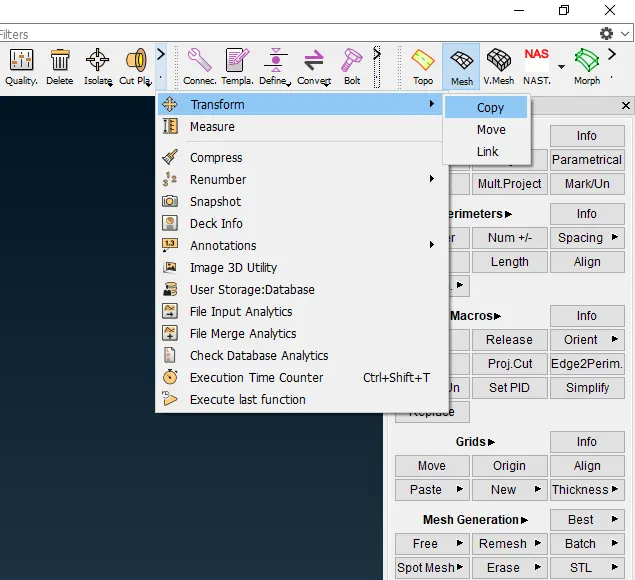
24) In inner pannel is used TRANSFORM--COPY--SYMMETRY using 3 points, because that model is symmetry
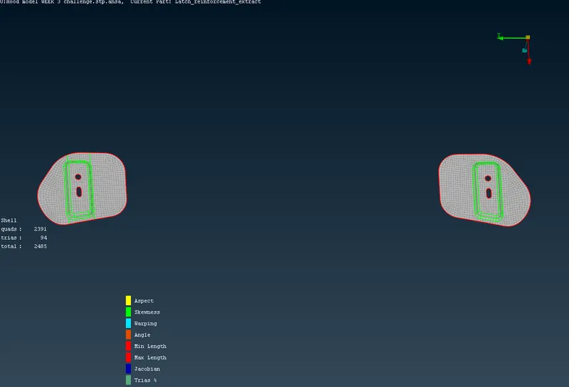
FINAL MODEL AFTER MESH--
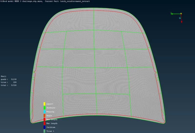
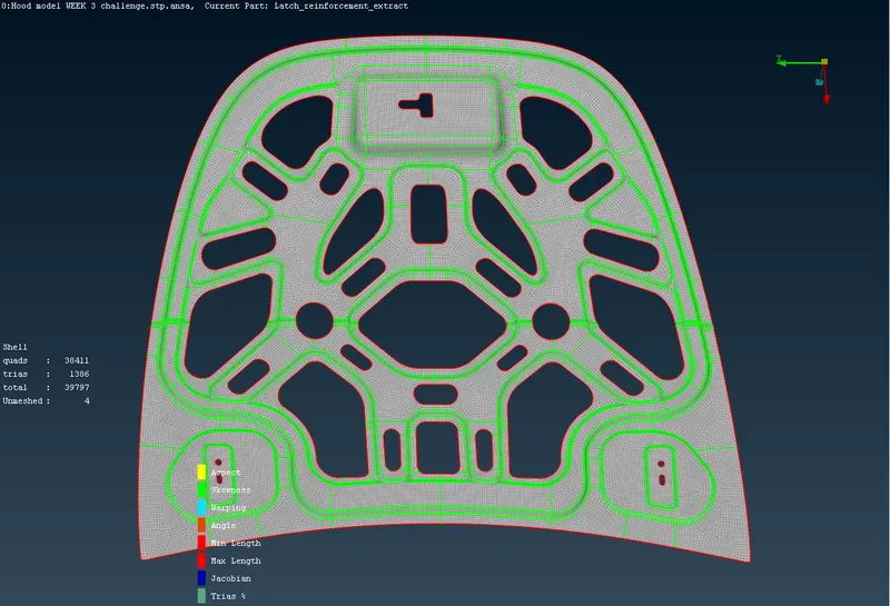
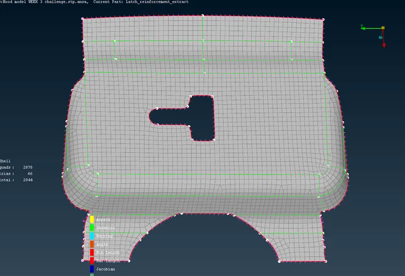
ASSEMBLY MODEL--
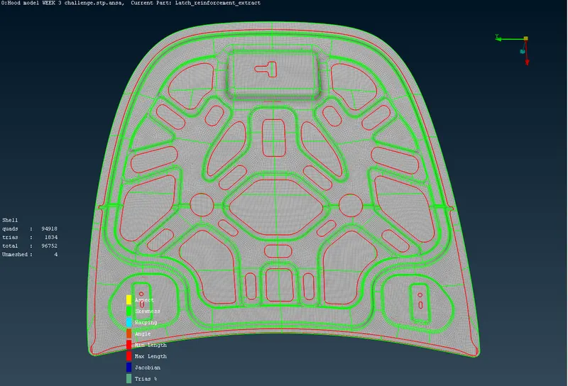
NOTE:-- ALWAYS CHECK THE ORIENTATION OF THE MODEL BEFOR AND AFTER THE COMPLETION.
CONCLUSION:--
1) Learnt about the basics of ANSA.
2) Learnt the initial step in ANSA
3) Learnt about Manual and Automatic mid surface.
4) Learnt how to remove trias and get better mesh flow.
5) Tools used to remove Trias.