Project - 2 - Meshing on the suspension Assembly
AIM:--
Meshing on the suspension Assembly
Deploying connection
Doing symmetry for other half
Represent suspension spring as 1D elements
About the Model:--
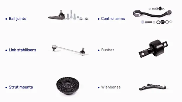
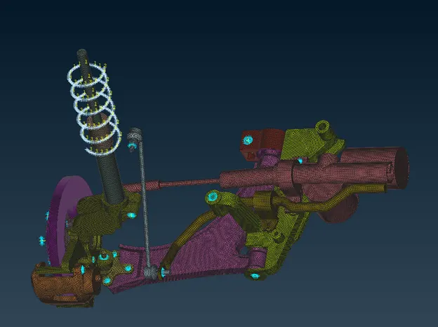
Suspension system: This connects the wheels to the chassis and uses springs, shock absorbers, link bars and control arms to cushion impact and allow relative motion
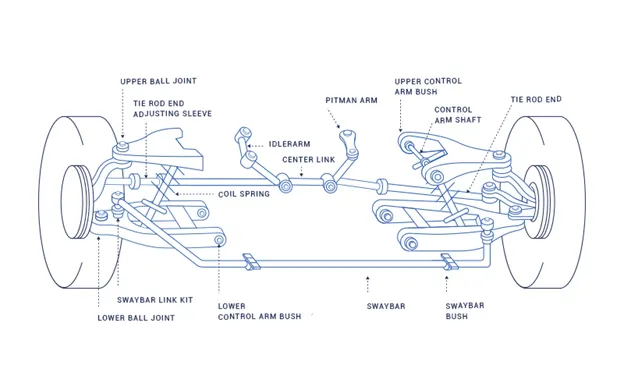
Suspension Parts:
PROCEDURE FOR MESHING:--
- First Import the model and do the topo on it to stich the surface properly.
- After topo, Model should be in YELLOW color.
- Now segregate the model in different components.
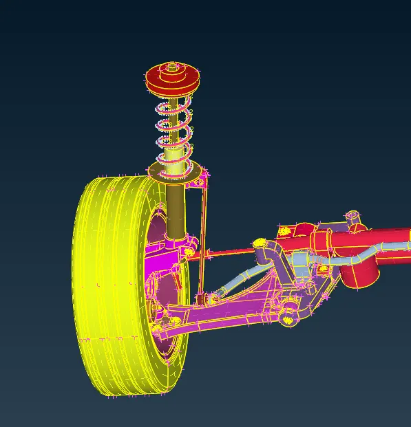
- Cleanup the geometry properly.
- Check--Geometry. This option helps us to fix many Geometrical error using AUTO FIX option.
- In this, we have to check the model individually. Because in this model some parts are very close to each other so ANSA may not be able to identify the error properly.
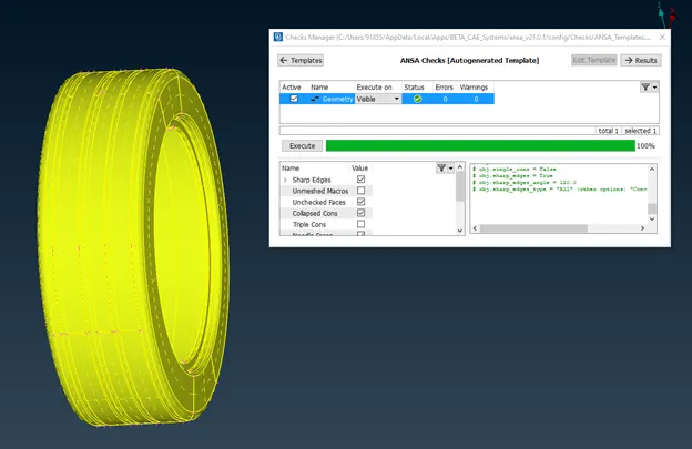
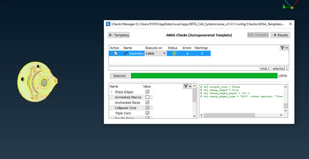
- In this way, we have to check of each and every components in model.
- If you find any error, fix that by AUTO FIX option or fix it manually.
- After fixing everything, change the length of each and every component to it TARGET elements length. It will help to place the node at interval of target length that is 4.
- In this model maximum components are of non-uniform thickness and thickness more than 5mm. So for this type of components we have to do VOLUME mesh.
- For Volume mesh, first we have to do the surface mesh using TRIAS & ORTHO TRIAS and the converting those surface mesh to Volume mesh.
- We will prefer ORTHO TRIAS for curve surfaces as it will capture the feature more accurately as compared to normal TRIAS.
- And NORMAL TRIAS for straight surfaces.
- Now set the QUALITY CRITERIA & MESH PARAMETER for volume mesh.
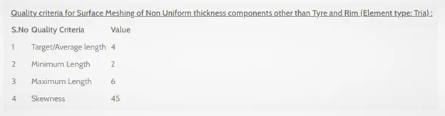
- Keep in mind very important that, there should not be RISE & KINK in the model.
- If these are present in the model, remove it properly so that there will be no TET COLLAPSE issue.
- In entire model, I have not compromise with FEATURE, because each and every components are very precise. So in left the failing element as it is, near the feature.
Some of these are
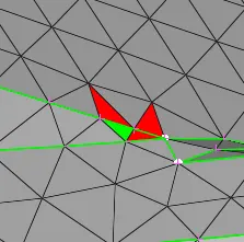
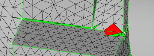
- After meshing we have convert the surface mesh into volume mesh.
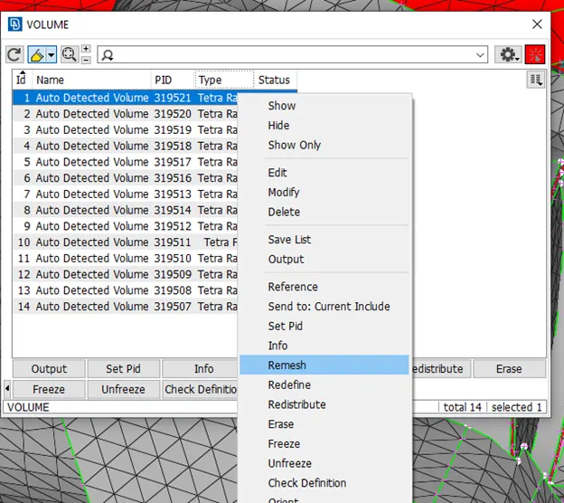
- For that first we have to DEFINE the component and then LIST the component and REMESH it.
- After this, check for TET COLLAPSE quality
TET COLLAPSE is one of the quality parameters, which will be checked while generating tetrahedral elements. It can be calculated by measuring the distance of a node from the opposite face, then each of the four values will be divided by the Square root of the opposite face's area

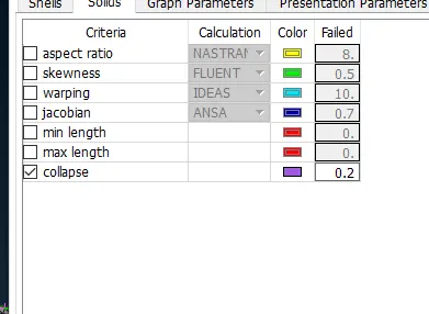
- Fix the TTE COLLAPSE by two option:--
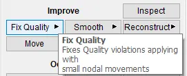
- FIX QUALITY
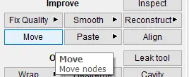
- MOVE FREE
- Check for RISE & KINK. There should not be any.
- To remove this MOVE the surface freely.
After Volume Mesh
- Now we will go for Meshing of TYRE & RIMS
- QUALITY CRITERIA & MESH PARAMETER
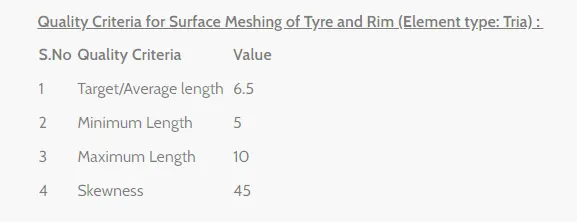
- Element type will be TRIA.
- There are many elements in this Tyre and Rim region because of feature is very small which is even less than Target elements length.
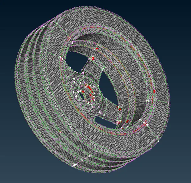
- Remove all the failing elements except nearby to the feature.
- Now there is 2 more components in the model which are of uniform thickness as well thickness is less than 5mm.
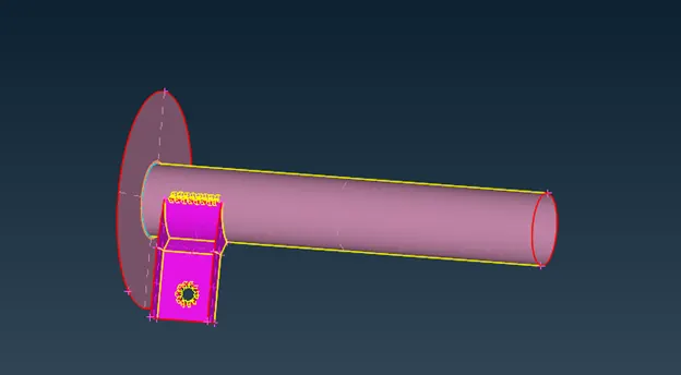
- For these two components we have to extract MID SURFACE by using SKIN option
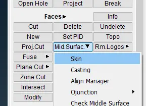
- Here we can go with manual mid surfacing also but in these components there were no feature, so AUTO MIDSURFACE is very exact.
- Now we have mesh the these two component
- Assign QUALITY CRITERIA & MESH PARAMETER for manual meshing. Element type will be mixed.
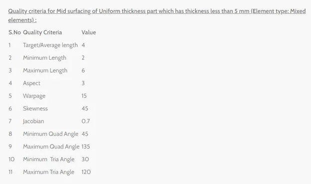
- Meshing is completed.
PROCEDURE FOR DEPLOYING CONNECTIONS:--
- Visualize the CAD properly so that we can deploy the proper connection.
- After visualize check whether there is any BOLT, SEAM LINE SEAM WELD connections are there or not.
- If not then deploy the connection manually based on your experience and model type.
- We will deploy BOLT connection on RIM & AXEL region or we can deploy RBE2 many nodes and then connect the two master nodes with RBE 2 nodes.
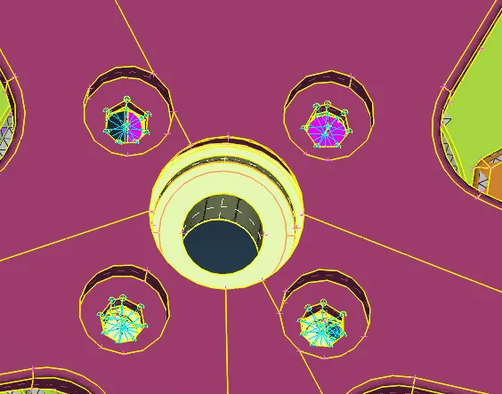
- Deploy SEAM LINE at CLAMPING & SUSPENSION
For that we have to first create FEA to curve in mesh deck. Then convert those curve into SEAM LINE. Now using connect option choose the part1 & part2 and choose FEA representation type as OVERLAP SHELL because parts are parallel to each other.
Step length will be same as target element size.
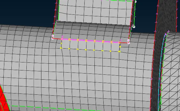
- Now deploy the RBE2 at AXLE AND WISHBONE region.
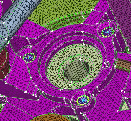
- Deploy CLUSTER RBE2 in all the all hole regions to connect two components.
- Connection is completed
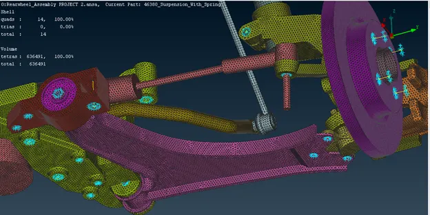
PROCEDURE FOR SYMMETRY THE OTHER HALF OF SUSPENSION.
Symmetry option are carried to save time and do the modeling precisely
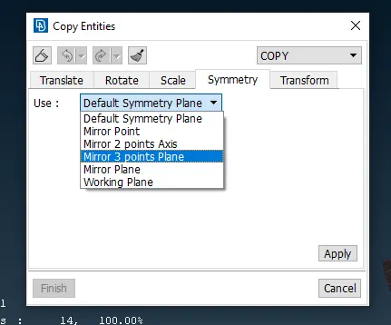
- Go to transform option.
- Select all the entities which have to symmetry.
- Go to symmetry tab choose 3 point plane
- Choose the 3 points from where you have to reflect the entities.
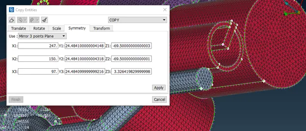
- Click apply and it is done.
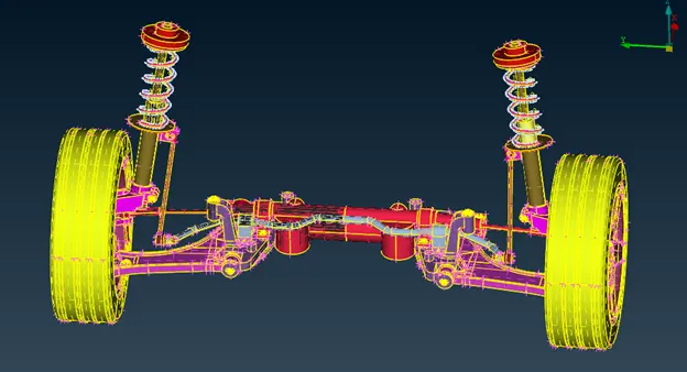
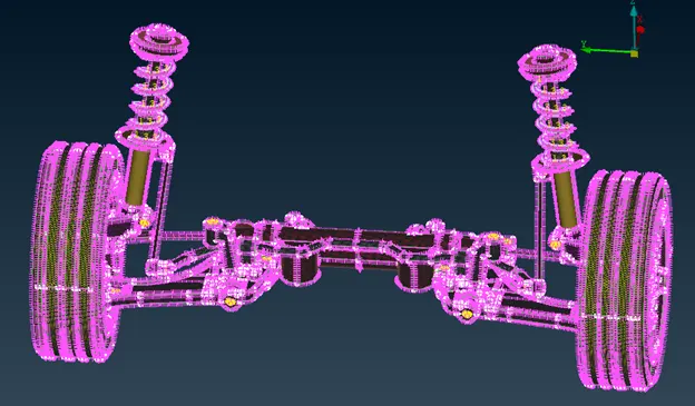
PROCEDURE FOR SYMMETRY THE OTHER HALF OF SUSPENSION.
Symmetry option are carried to save time and do the modeling precisely
- Go to transform option.
- Select all the entities which have to symmetry.
- Go to symmetry tab choose 3 point plane
- Choose the 3 points from where you have to reflect the entities.
- Click apply and it is done.
Represent suspension spring as 1D elements
- Generate a middle curve of spring. By using middle option in curve.
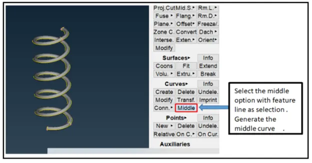
- Convert the curve into single curve. BY using connect—multi option.
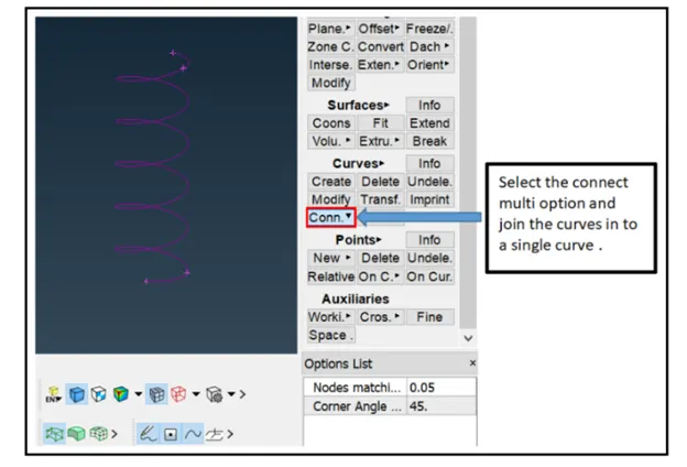
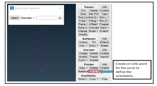
- Create COG point of curve to define orientation
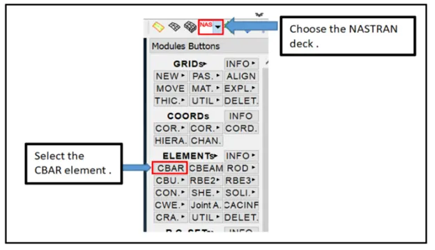
- Select the CBAR elements
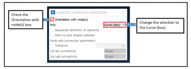
- Change the selection type to curve
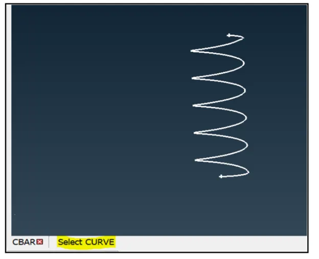
- Select the curve and give middle click
- Select the orientation mode
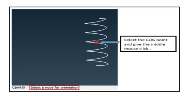
- Specify the element length 3mm
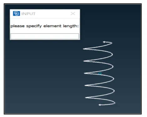
- Now middle click and define the PID
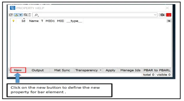
- Define are by giving Radius of spring i.e cross section radius of spring
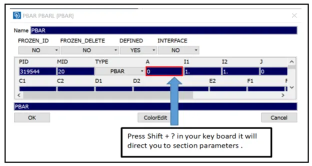
- After the assign the cross section area and MOI. 1D elements will be created
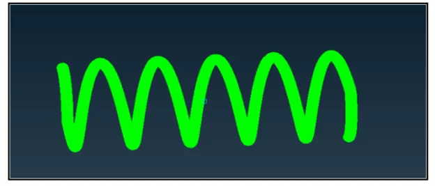
- To represent 1D as 3D elements. Check the box 1D detailed repsentation with solid in quality parameter
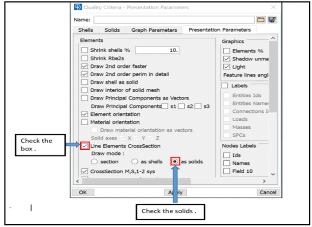
- Click apply and ok.
- A CBAR elements is a kind of simplified CBEAM elements and should be used whenever the cross section of the structure and its property is constant and symmetry.
Conclusion:--
- Learnt about deploying connection
- Learnt about converting to 1D elements
- Learnt solid meshing and how to remove TET COLLAPSE
- Mid surface extraction
Google drive link :-- https://drive.google.com/file/d/122cZd2oZn0INCOu8CyyQq90WP58cMLYz/view?usp=sharing