Assignment 5-RADIOSS Interfaces & Study of Effect of Notches Challenge
AIM:--
1) To deploy 2D shell on BUMPER component with target size as 6mm.
2) To change the various parameter for the crash tube as per the question.
3) Do the post-processing (Plot graph and compare each case).
PROCEDURE:-- (BUMPER MESHING)
1) Import the model
2) Do the geometry cleanup if needed.
3) Connect the middle rail beam to the extreme rail beam using extend the option

4) After extending
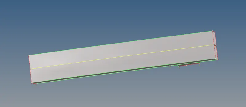
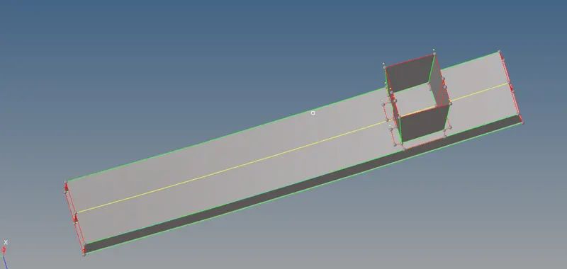
5) Now attach the crash box. By extend over edge option.

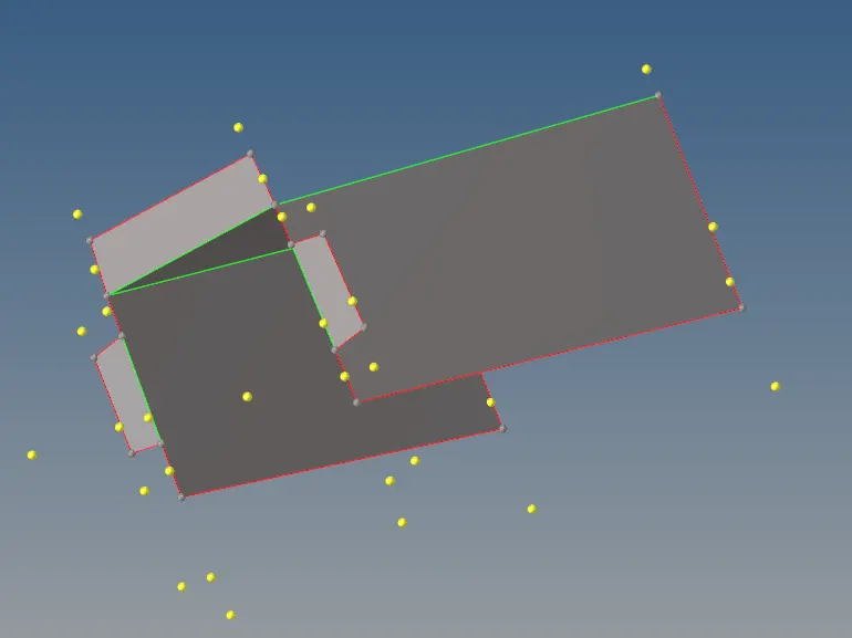
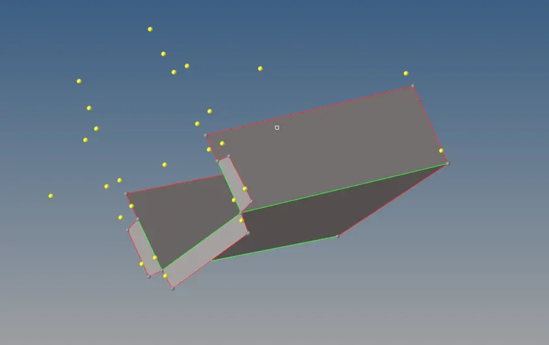
7) Now we have to mesh the component. Target Element size 6
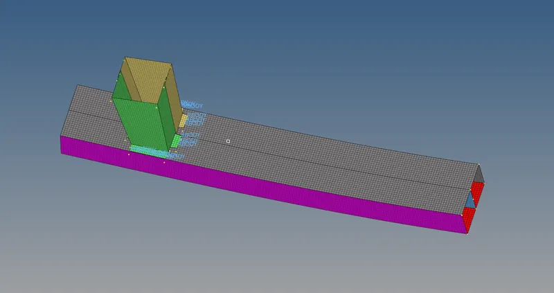
8) After meshing we have to connect the crash box to the beam section. By creat rigids

9) Select the nodes and connect

10) After meshing entire model
PROCEDURE:--
CASE-1 (RUN THE CRASH TUBE AS IT IS)
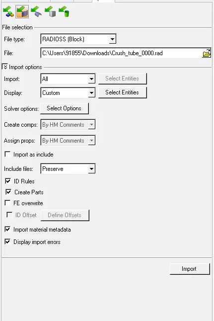
1) First import the 0000.rad
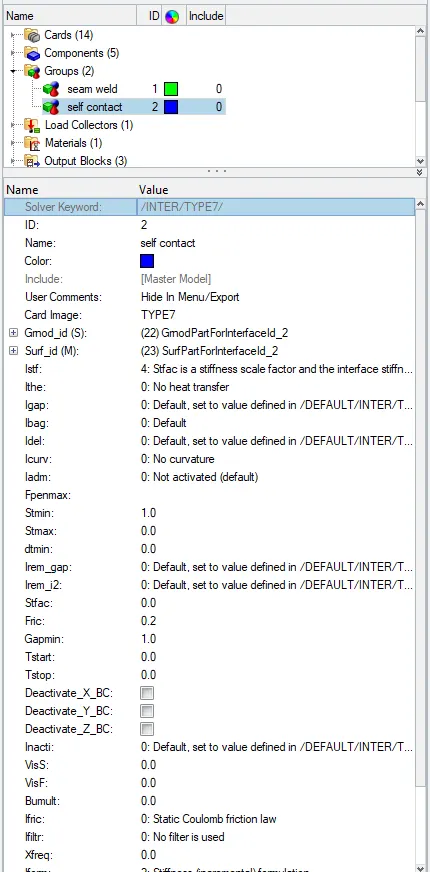
2) Go to GROUPS for interface
3) Creat TH/PART for the interface from the group
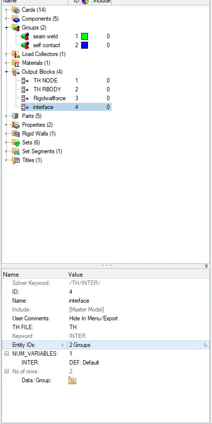
4) We don't have to change anything as per the question
5) Run the analysis to see the animation of deformation.


6) After running we will get a JOB IS COMPLETED window. Click Result to see the animation
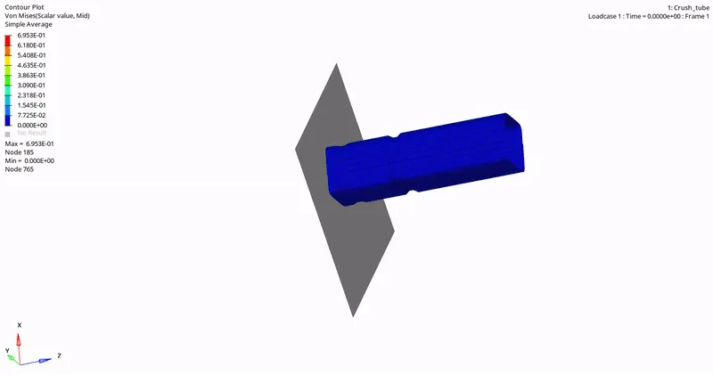
7) Now Plot the graph for the RIGID WALL
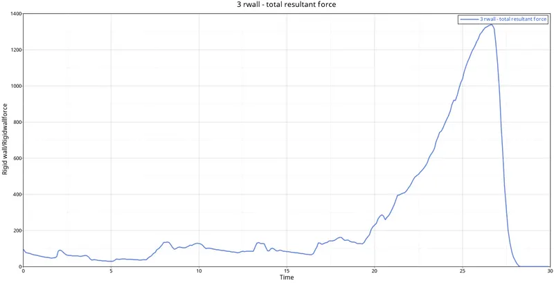
Here rigid wall force is increasing as the velocity increase, but it reaches its peak once when the entire tube collides with the rigid wall. Due to this contact energy also increases.
8) Now plot the graph for contact energy.
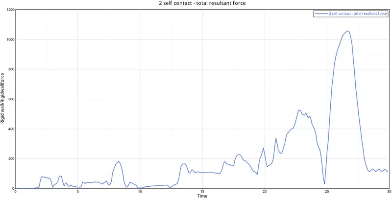
Initially, it will start from zero then it will fluctuate and after that, it will reach a peak once it collides.
9) Internal energy graph
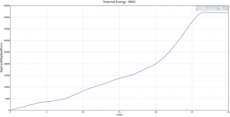
Internal Energy starts increasing from zero and reaches a peak when it collides and the internal energy becomes constant.
CASE-2 (CHANGE Inacti=6 AND RUN)
1) Import the model
2) Change the Inacti=6
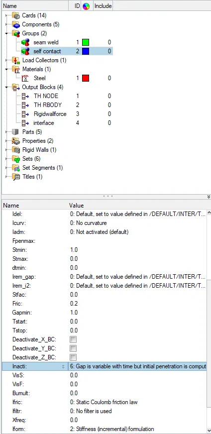
3) Run the analysis to see the animation of deformation.
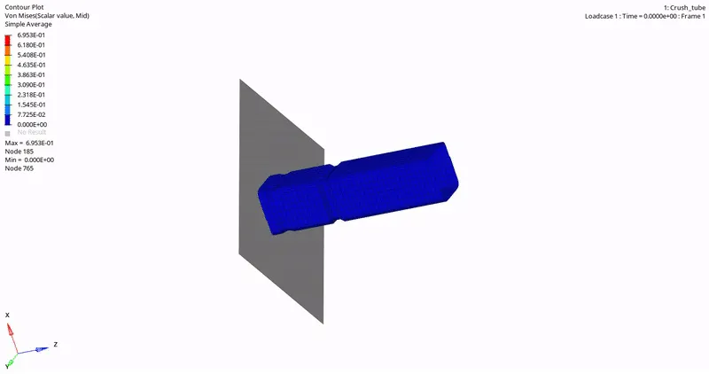
4) Now Plot the graph for the RIGID WALL
Here rigid wall force is increasing as the velocity increase, but it reaches its peak once when the entire tube collides with the rigid wall. Due to this contact energy also increases
5) Now plot the graph for contact energy.
Initially, it will start from zero then it will fluctuate and after that, it will reach a peak once it collides.
6) Internal energy graph.
Internal Energy starts increasing from zero and reaches a peak when it collides and the internal energy becomes constant.
CASE-3 (CREAT TYPE 11 AND RUN)
1) Import the 0000.rad file
2) Change the id card to TYPE 11
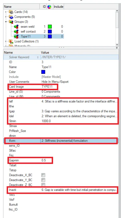
3) Creat the TH file in the output block and specify the group.
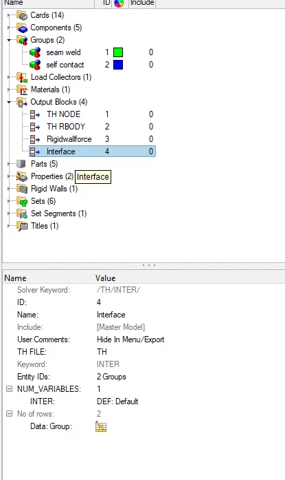
4) Run the analysis to see the animation of deformation
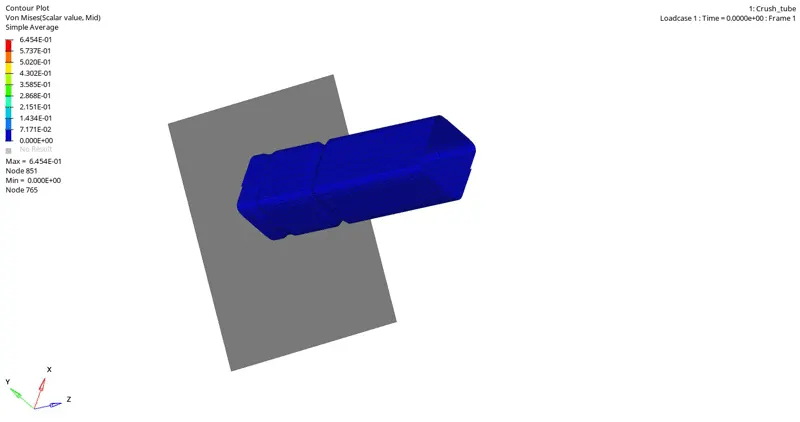
5) Now Plot the graph for the RIGID WALL
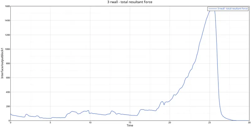
Rigid wall force start from certain force and increase as velocity increase and reaches a peak when whole body collides and after the collision, it becomes zero
6) Graph for type 11 contact force
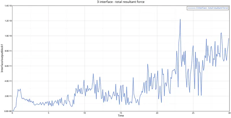
Contact Energy start from zero and then fluctuate for some region and then reaches a peak and starts fluctuating again
7) Graph for internal energy
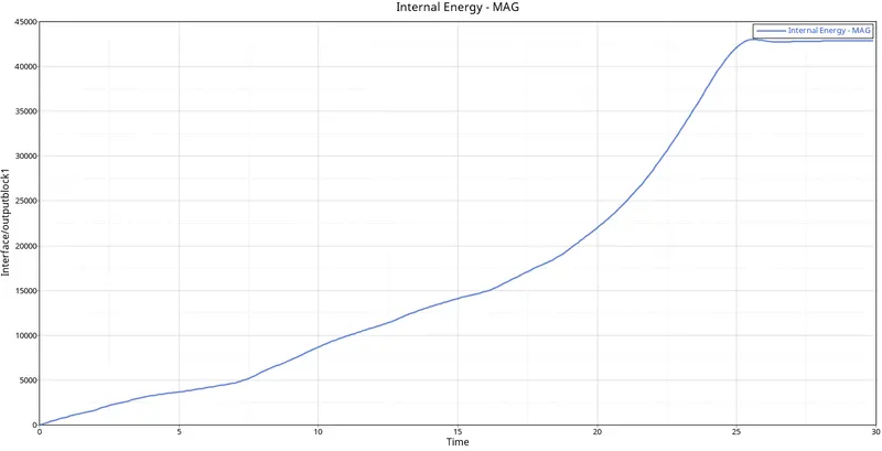
Internal Energy starts increasing from zero and reaches a peak when it collides and the internal energy becomes constant
8) Graph for 2-Self contact
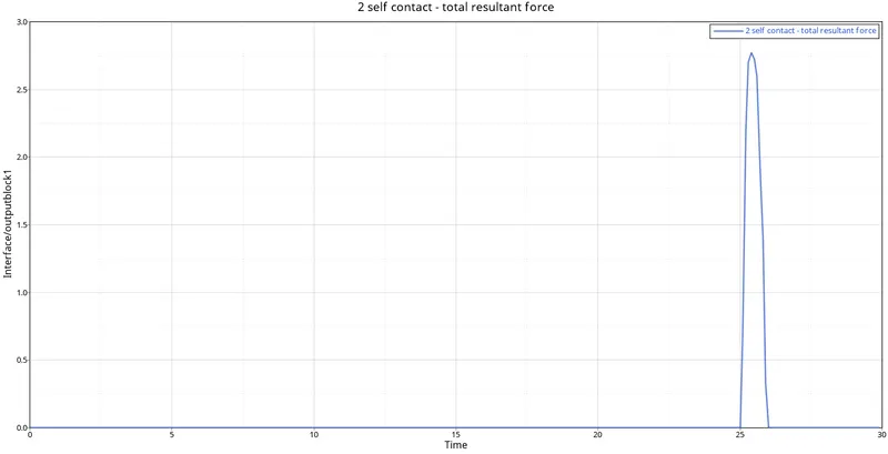
Contact energy is constant and instant increases to peak once the body collides with a rigid wall.
CASE-4 (REMOVING THE NOTCH AND BOUNDARY CONDITION)
1) Import the model
2) Remove the notch. By using align nodes

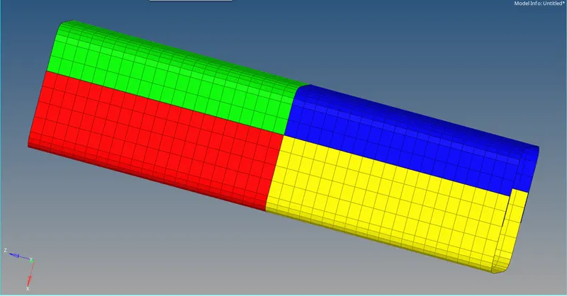
3) Delete the Boundary condition
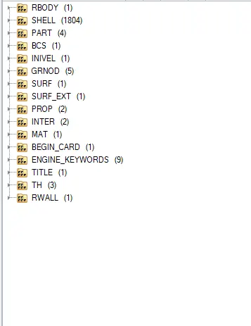
4) Run the analysis to see the animation of deformation
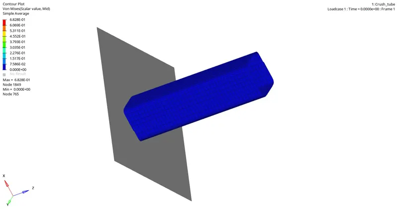
5) Now Plot the graph for the RIGID WALL
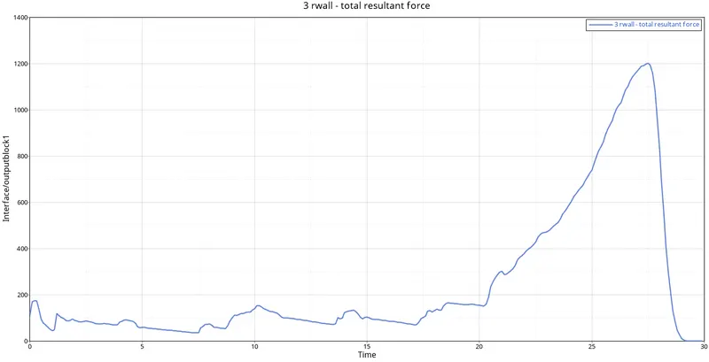
Rigid wall force start from certain force and increase as velocity increase and reaches a peak when whole body collides and after the collision, it becomes zero
6) Graph for Internal Energy
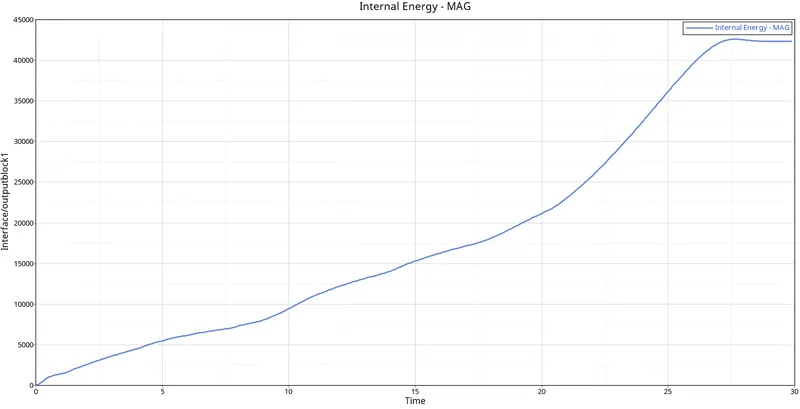
Internal Energy starts increasing from zero and reaches a peak when it collides and the internal energy becomes constant
7) Graph for contact energy
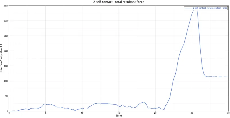
Contact energy starts from zero and increase slightly and reaches a peak when the collision of body and component takes place
CASE-5 (CREATING NOTCH IN THE MIDDLE AND RUN)
1) Import the model/
2) Creat notch in the middle. By using the TRANSLATE option ( shift+f4). Magnitude 2.500 (user-specified) or 2D--Element offset.

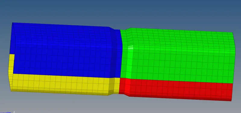
3) Run the analysis to see the animation of deformation.
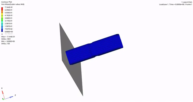
4) Plot the rigid wall graph.
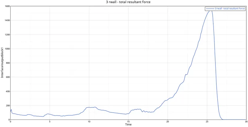
Rigid wall force start from certain force and increase as velocity increase and reaches a peak when whole body collides and after the collision, it becomes zero
5) Plot internal energy graph.
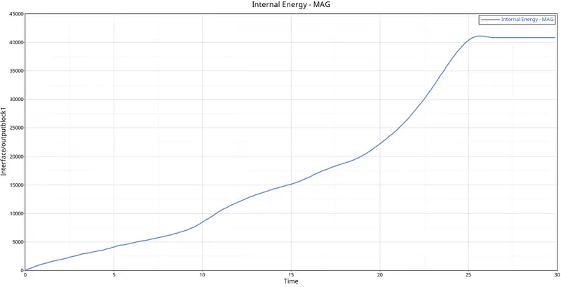
Internal Energy starts increasing from zero and reaches a peak when it collides and the internal energy becomes constant
6) Plot interface/contact energy.
Contact energy starts from zero and increase slightly and reaches a peak when the collision of body and component takes place
CASE-6 (CREAT NOTCH IN THE OPPOSITE SIDES OF MODEL AND RUN)
1) Import the model.
2) Creat notch in the opposite of the model. By using the TRANSLATE option ( shift+f4). Magnitude 2.500 (user-specified) or 2D--Element offset
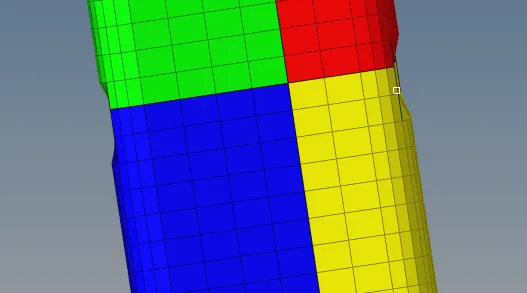
3) Run the analysis to see the animation of deformation.
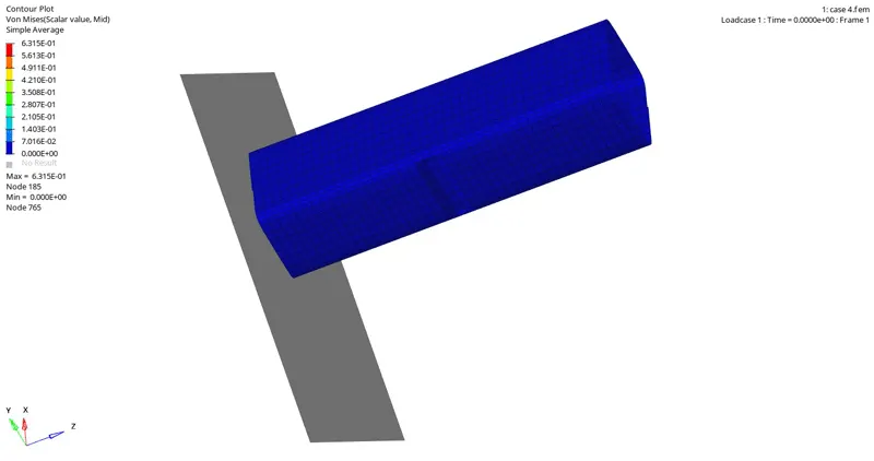
4) Plot the rigid wall graph.
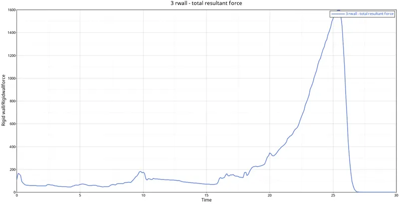
Rigid wall force start from certain force and increase as velocity increase and reaches a peak when whole body collides and after the collision, it becomes zero
5) Plot internal energy graph.
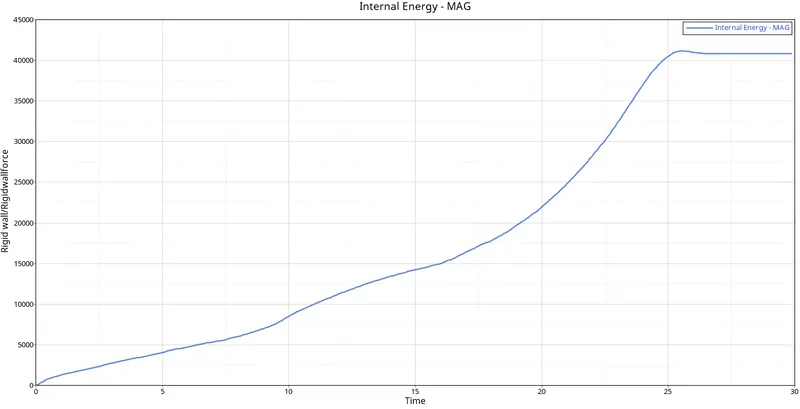
Internal Energy starts increasing from zero and reaches a peak when it collides and the internal energy becomes constant
6) Plot interface/contact energy.
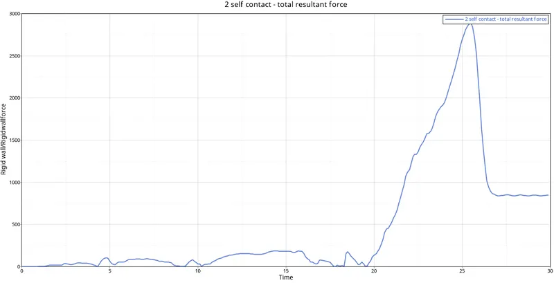
Contact energy starts from zero and increase slightly and reaches a peak when the collision of body and component takes place
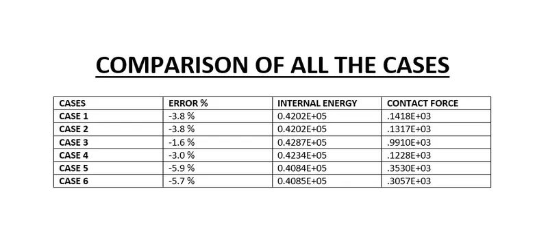
CONCLUSION:--
1) Brushed up my meshing technique.
2) Learnt about the different interfaces and their characteristics.
3) Deploy connection in the crash tube.
4) Do post-processing for various cases.