Week - 4 - 2D meshing for Plastic components
AIM:-
For the given Plastic Bottle Cap model, check for the geometrical errors and take the mid surface by suitable mid surfacing techniques. PID and Thickness assignment has to be done for all the mid surfaces. Mesh the same with given element Quality criteria.
PROCEDURE:-
1) First import the model.
2) Visualize the model properly, so that you can get an overall idea about the model and how to proceed.
3) After analyzing, Check for CYAN colour CONS because all the Model should have only YELLOW colour line.
4) Orient the Model.
5) Now use CHECK--GEOMETRY--EXECUTE from the utility section. This function locates geometrical problems of the model such as Unmeshed Macros, Unchecked Faces, Needle Faces, Collapsed Cons, Triple Cons, Overlaps and Cracks.
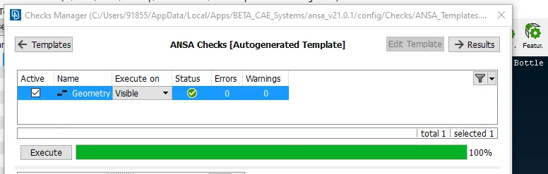
6) Using this option some of the geometrical issues can be fixed AUTOMATICALLY and the rest you can fix it MANUALLY.
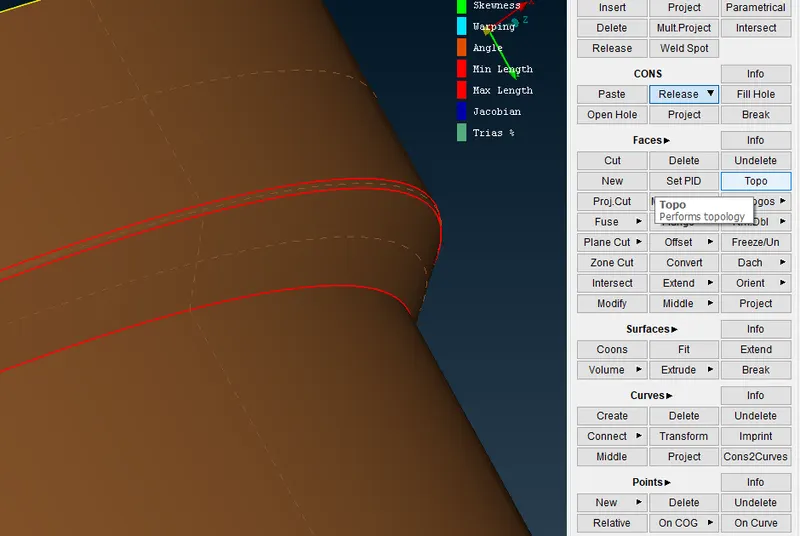
7) Process to remove CYAN colour line. First RELEASE the line then do TOPPO by BOX selection. It will convert in yellow colour.
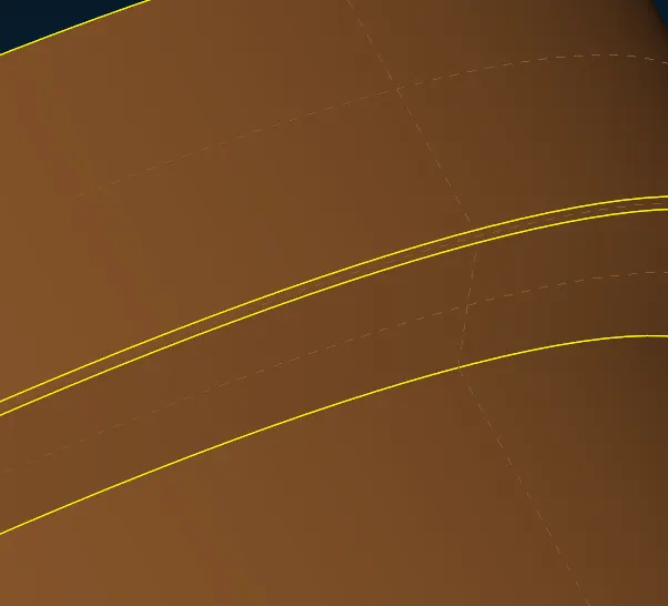
AFTER CLEAN PARENT MODEL
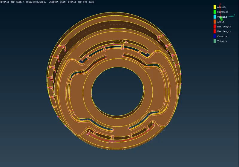
8) Now we are good to go for Extracting MID SURFACE.
9)There are 3 way of extracting
- FACES--MIDDLE--SINGLE/MULTI
- OFFSET
- MID SURFACE
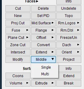
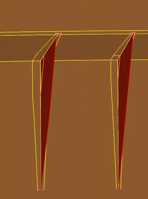
All the ribs are extracted by MIDDLE--MULTI
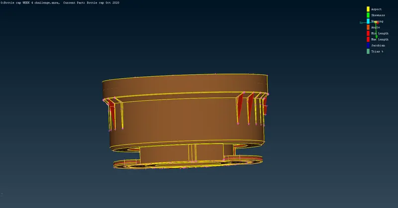
Main Cylinder is extracted by OFFSET option.
10) Procedure to extract the bottle cap THREAD
CURVE--MIDDLE
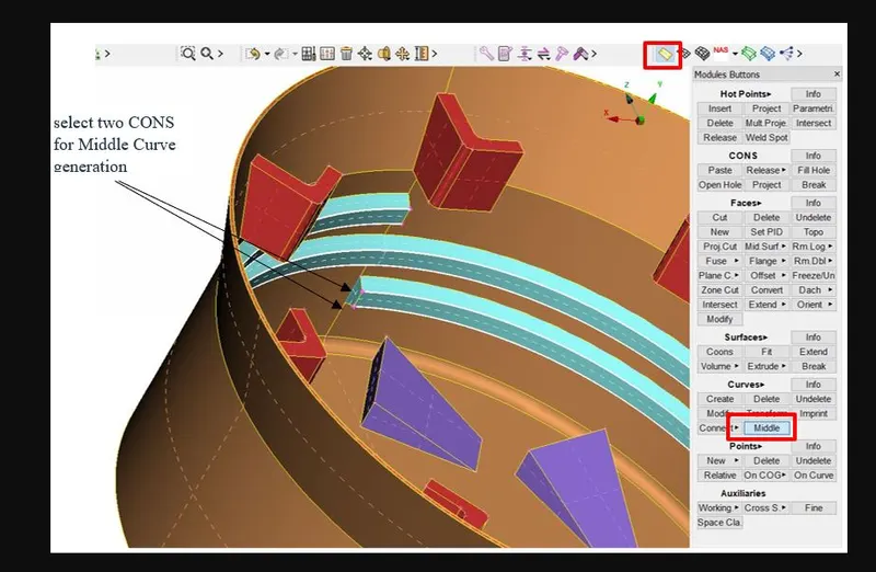
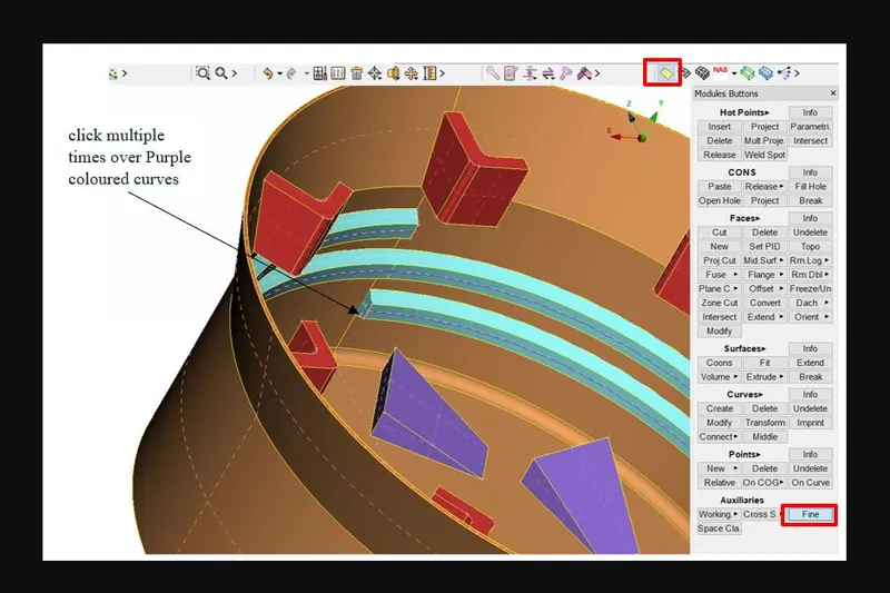
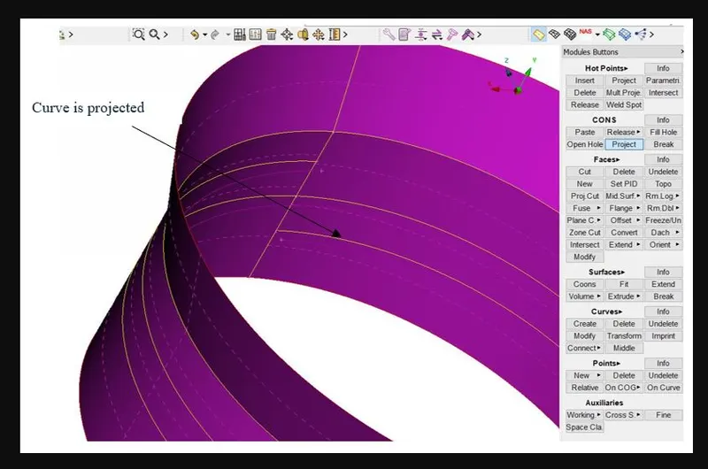
Now project the middle CURVE line to base surface and creat NEW surface

11) Procedure to extract the bottle cap TEETH
Select the two sides of TEETH using MIDDLE--SINGLE option and then PROJECT it to base surface and creat NEW surface
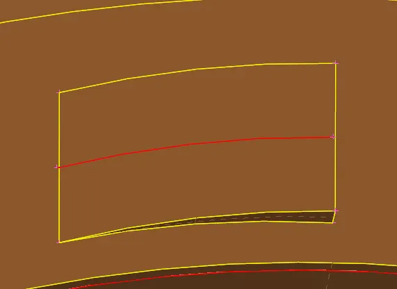
12) Extract the mid surface using same option for this area
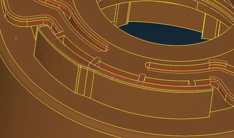
12) Use the OFFSET option to creat mid surface for rest area and use only one orientation INNER or OUTER perimeter to OFFSET.
13) OFFSET value should be half of thickness.
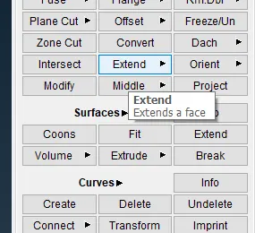
14) Extend the ribs by using EXTEND option in FACE bar
15) AFter extraction FINAL MODEL
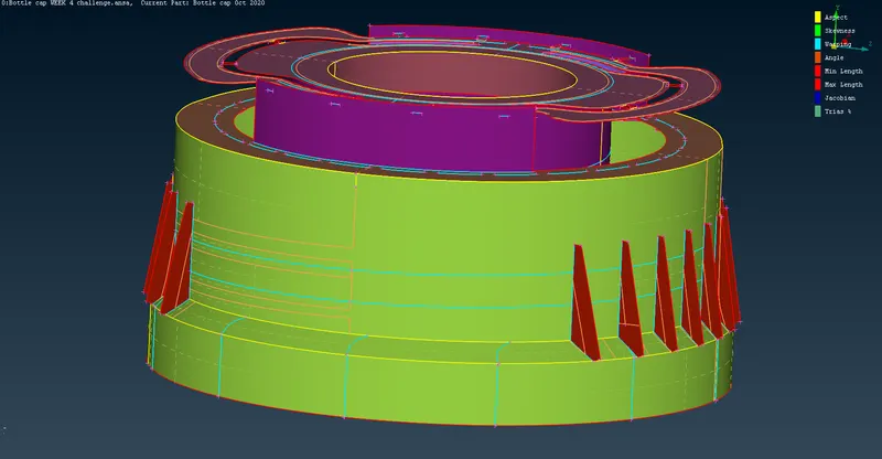
16) Go for CHECK--GEOMETRY for assurance.
17) Now we are good to go for MESHING.
18) Before meshing follow these steps
- Assign QUALITY CRITERIA by pressing F11.
- Assign Mesh Parameter.
- Now assign the length from the MESH tab and assign the perimeter as TARGET LENGTH.
- Check for orientation also.
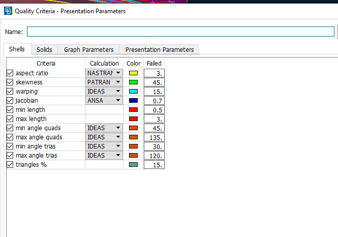
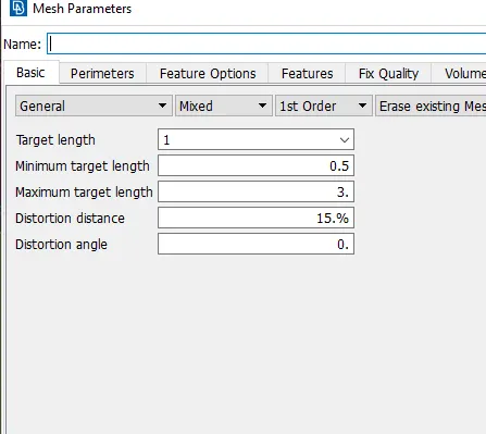
19) Now start meshing by area by area.
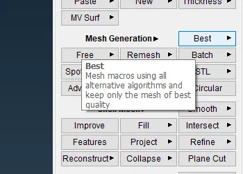
20) Use BEST from MESH GENERATION
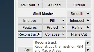
21) Use RECONSTRUCT to remesh the MACRO. The Re-construction function is a powerful tool for the creation of a high quality surface mesh. It examines a given mesh and performs re-meshing to correct problematic areas and optimize the overall quality of the mesh according to the mesh parameters. For Geometry Mesh (Macro Areas) all modifications are made on the underlying CAD surface.
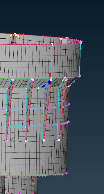
22) Some of the elements will fail for MINIMUN length and ASPECT RATIO near CYAN colour line. Because of TRIPLE CON & HOT POINTS and it is totally preferable in this case.

23) Some elements will fail here also for same reason.
24) After MESH model MODEL
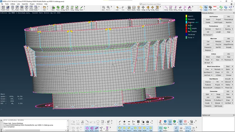
25) Check for quality criteria. Remove OFF elements, but it oK to have for complex geometry
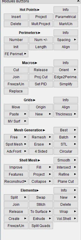
26) Remove unwanted tria using
- SPLIT
- SWAP
- JOIN
- PASTE SMOOTH
- follow these step also
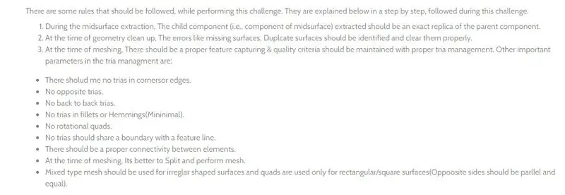
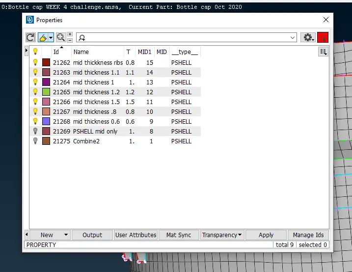
27) After all of these assign THICKNESS to every part
MACROS--SET PID--assign the thickness to every part.
CONCULSION:--
1) Learnt other way of extracting MID SURFACE.
2) Learnt how to assign thickness.
3) More tools to clean up Geometry.
4) Proper Mesh flow.