Assignment 7-Side Pole Crash Simulation Challenge
Aim:--
Side Pole Crash Simulation Challenge
- Create an appropriate interface, friction 0.2, and recommended parameters.
- Make sure of no penetrations and intersections.
- Correct rigid bodies if any issues.
- Create a cylindrical rigid wall with friction 0.1.
- Compare the model weight with the full-scale 300k nodes model and use added masses to reach a target weight of 700kg while getting CG about the required range
- Initial velocity 35 mph.
- Use a model checker to ensure good quality.
- Time-step :0.5 to 0.1 microseconds.
- Run 80 ms.
- The intrusion at B pillar, hinge pillar, and fuel tank region. Provide recommendations on what can help to reduce Fuel tank intrusion.
- Sectional force in the cross member.
PREREQUISITES:--
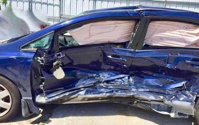
Broadside collisions are where the side of one vehicle is impacted by the front or rear of another vehicle, forming a "T". In the United States and Canada this collision type is also known as right-angle collision or T-bone collision; it is also sometimes referred to by the abbreviation "AABS" for "auto accident, broadside". Vehicle damage and occupant injury are more likely to be severe, but severity varies based on the part of the vehicle that is struck, safety features present, the speeds of both vehicles, and vehicle weight and construction.
When a vehicle is hit on the side by another vehicle, the crumple zones of the striking vehicle will absorb some of the kinetic energy of the collision. The crumple zones of the struck vehicle may also absorb some of the collision's energy, particularly if the vehicle is not struck on its passenger compartment. Both vehicles are frequently turned from their original directions of travel. If the collision is severe, the struck vehicle may be spun or rolled over, potentially causing it to strike other vehicles, objects, or pedestrians. After the collision, the involved vehicles may be stuck together by the folding of their parts around each other.
An occupant on the struck side of a vehicle may sustain far more severe injuries than an otherwise similar front or rear collision crash.
Side-impact airbags can protect vehicle occupants during side collisions, but they face the same limitations as other airbags. Additionally, side-impact wrecks are more likely to involve multiple individual collisions or sudden speed changes before motion ceases. Since the airbag can only provide protection during the first collision, it may leave occupants unprotected during subsequent collisions in the crash. However, the first collision in a crash typically has the most severe forces, so an effective airbag provides maximum benefit during the most severe portion of a crash.
Broadside collisions are frequently caused by a failure to yield right of way. In the case of collisions in an intersection, the cause is often a result of one vehicle failing to obey traffic signals (fail to stop or running past a red light). As with any crash, increased speed may increase crash severity
PROCEDURE:--
PROCEDURE:--
STEP 1—CHECK COG POINT
- Initially changing the CENTRE OF GRAVITY by using CRASH application
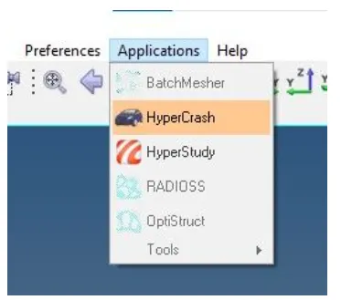
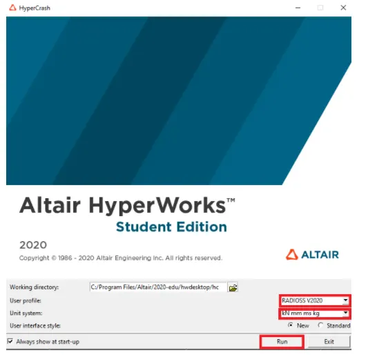
- After changing the units, Import the files in crash.
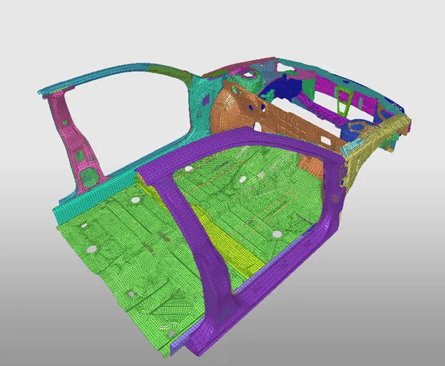
- To change the center of gravity go to MASS-BALANCING
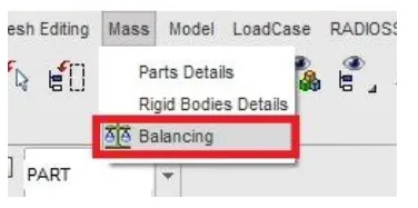
- View the center of gravity
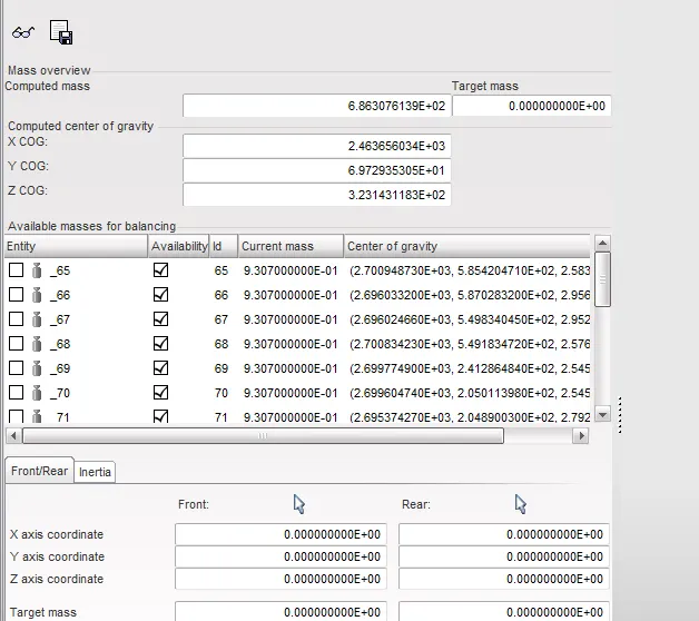
- The initial position of COG is
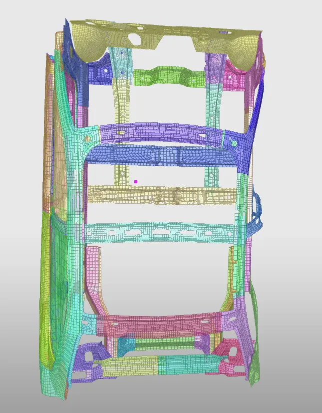
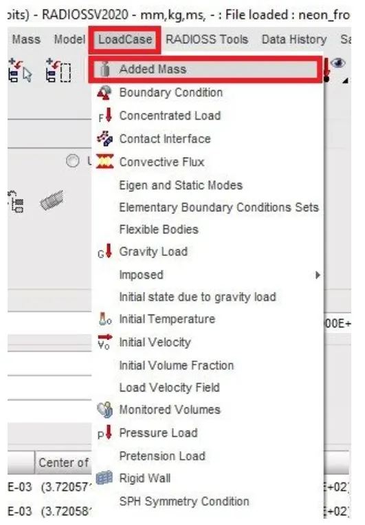
- Now mass should be added in all the passenger seat of 1 kg. To add go to LOAD CASE—ADDED MASS—CREAT NEW—TYPE1
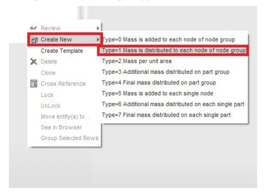
- To select the nodes ADD/REMOVE NODES IN THE GRAPHICAL AREA
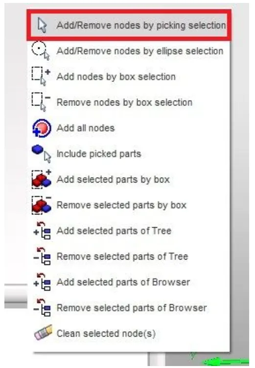
- After this select the nodes
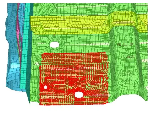
- Hit yes and save the changes
- Now do the same for all the three remaining seats.
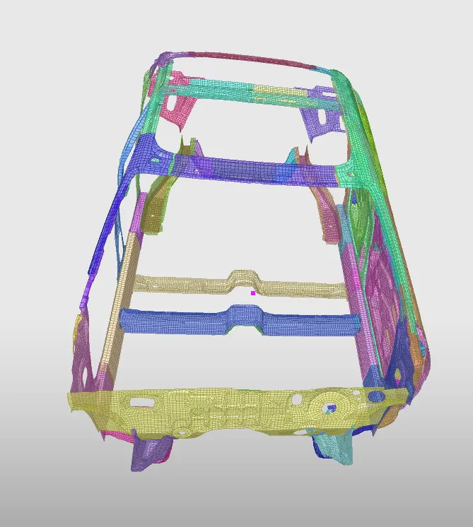
- After do the same. COG will come on center
STEP 2—PENETRATION CHECK
- Now save the model and open the same model in Hypermesh
- Now check for penetration TOOLS—PENETRATION CHECK.
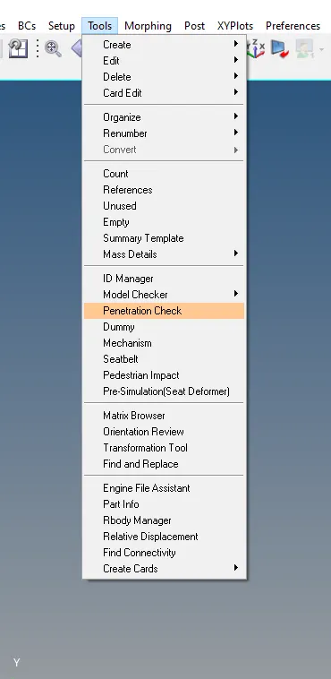
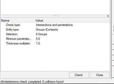
STEP 3—CREATING INTERFACE
- Create TYPE 7 interface using recommended parameters
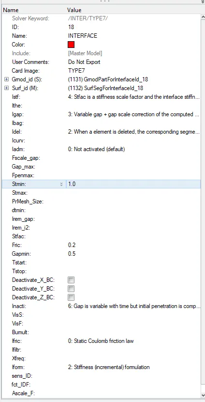
-
STEP 4—CREAT RIGID WALL
- Go to SOLVER DECK—RIGHTCLICK CHOOSE RWALL—PLANE
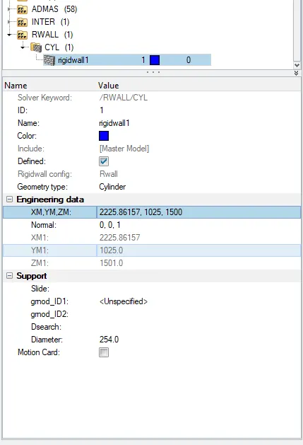
THERE SHOULD BE 5-10MM DISTANCE BETWEEN COMPONENT AND RIGID WALL.
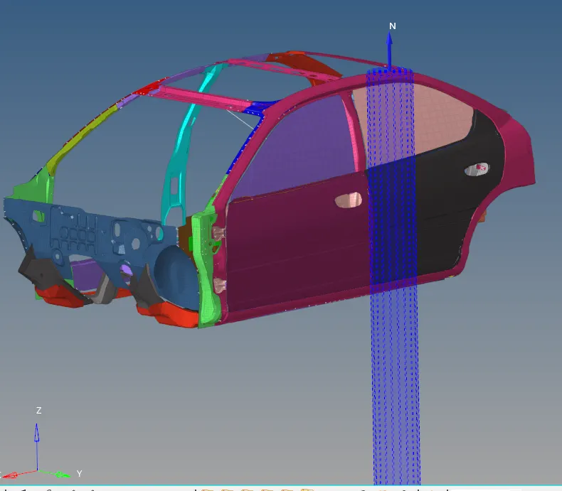
- FRICTION value should be 0.1
STEP 4—APPLY BOUNDARY CONDITION
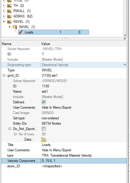
- INITIAL VELOCITY/INIVEL
- SOLVER BROWSER—RIGHTCLICK—BOUNDARY CONDITION—INIVEL
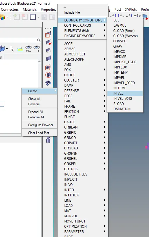
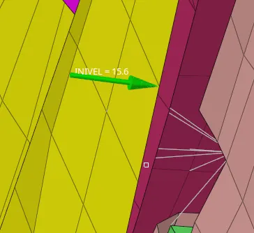
- Change the 35mph to mps that will be equals to 15.6
-
STEP 5—CREATE SECTION
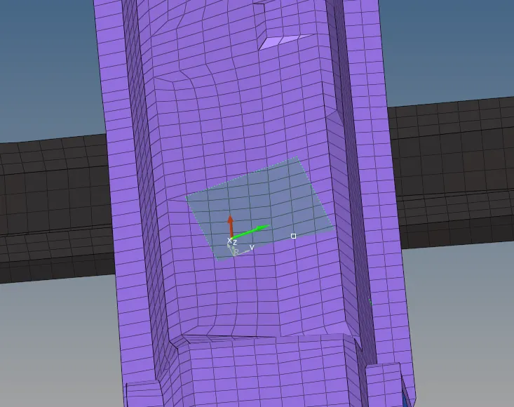
- Before section we have to define the moving frame
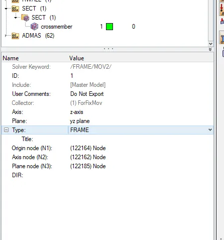
To define that go to SOLVER DECK—RIGHTCLICK—FRAME—MOVE
WE HAVE TO CREAT FRAME ON CROSS MEMBARE
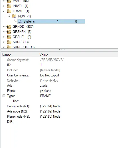
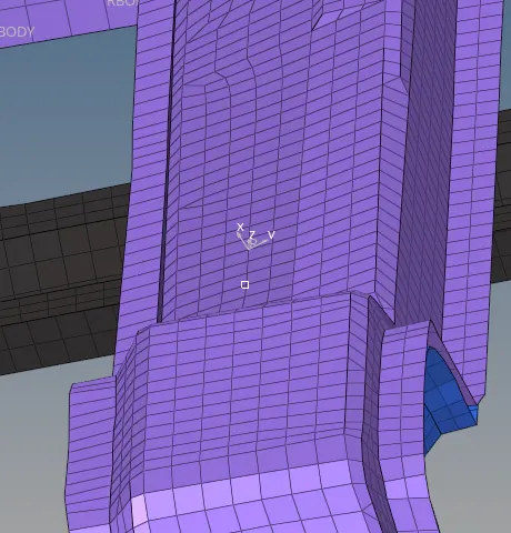
STEP 6—CREAT SECTION FOR THE FRAME
- To create section go to SOLVERDECK—RIGHTCLICK—SECT—SECT
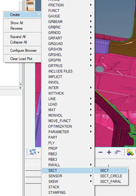
- Define the frame_id & grshel_id
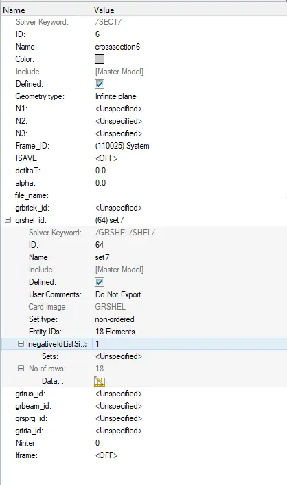
To create grshell_id right click on that and hit create now choose the elements nearby of the frame
STEP 7—CREATE INTRUSION
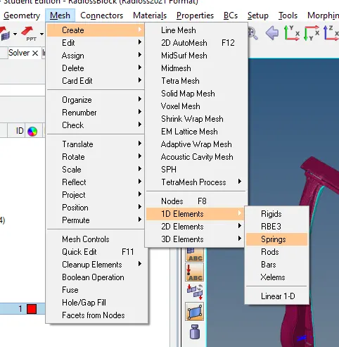
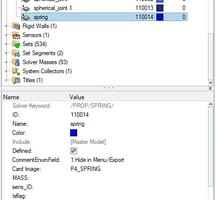
- To create intrusion go to MESH—CREATE—1D SPRING.
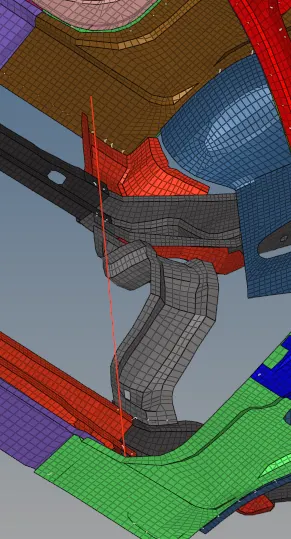
- Now define the property for the spring component. And assign its component also
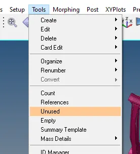
STEP 8—DELETE THE UNUSED AND EMPTY FILES FROM CRASH
- For this go to TOOLS—UNUSED—SELECT AND DELETE.
- Also, delete the empty card as well
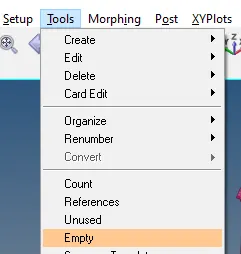
THIS MEANS THERE IS NO EMPTY AND UNUSED CARD IN THE MODEL WHICH MAY CAUSE ERROR
STEP 9—RUN THE MODEL CHECKER IN CRASH
- Import the model in crash application.
- Now go to QUALITY—MODEL CHECKER—RUN
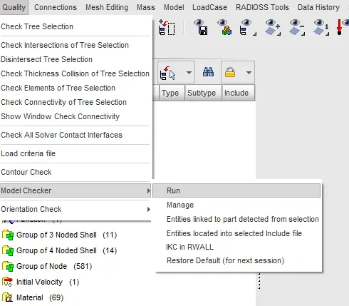
- It is best practice to do so that model will be very clean.
- But there are some genuine warning & those are totally acceptable.
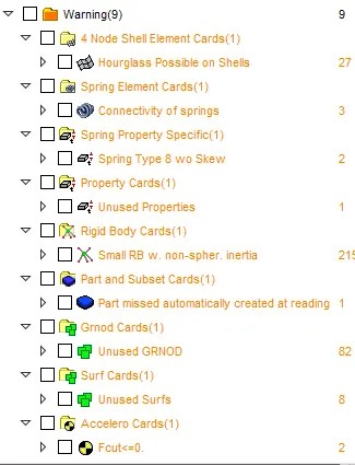
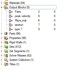
- STEP 10-- CREATE AN OUTPUT BLOCK
- Creat output block for Intrusion, section, Interface, peak velocity
POST PROCESSING:--
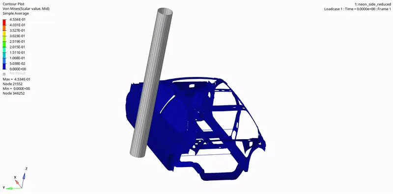
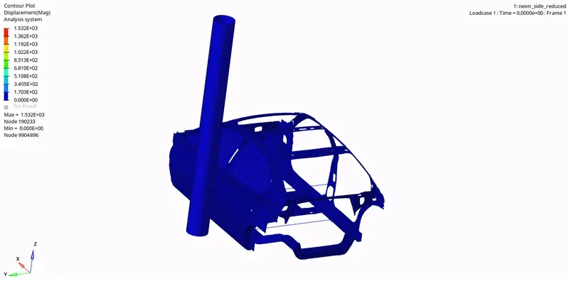
1. Upload .h3d file in hyper view to see the animation of deformation.
Von-misses deforamtion animation
Displacement deformation animation
2. Upload .T01 file in hypergraph to plot the output blocks graph
a) Plotted graph for KINETIC ENERGY, INTERNAL ENERGY, HOURGLASS,TOTAL ENERGY
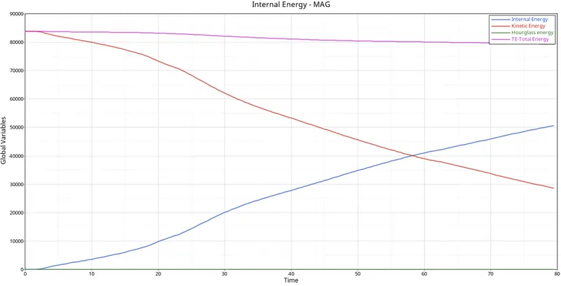
HOURGLASS ENERGY- It will constant throughout the run because the parameter in the property shell elements is recommended one.
KINETIC ENERGY- It will decrease after the collision due to a decrease in velocity.
INTERNAL ENERGY- It will increase due to falling in kinetic energy as it stores it as internal energy only.
TOTAL ENERGY- It will decrease a little bit because it totally depends upon KE & IE
b) Plotted graph is for VELOCITY VARIATION
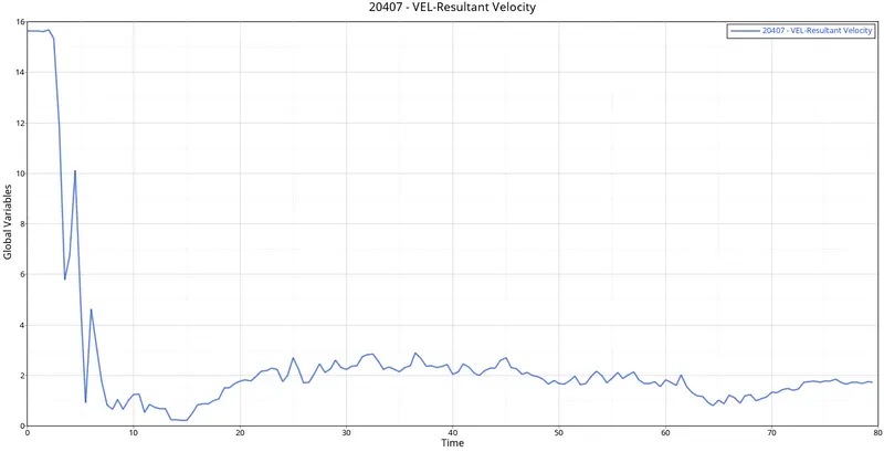
PEAK VELOCITY- It will decrease due to the cause of interia and It starts from peak because it colliding toward the rigid wall and it does come to rest at once.
c) Plotted graph is for CROSS MEMBERS
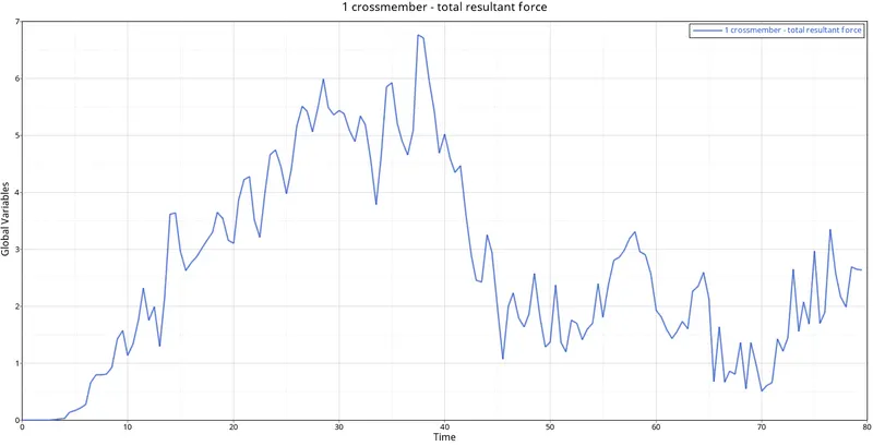
CROSS MEMBERS- It will not starts from origin and follows a zig-zag pattern. Because of having different types of components and so total resultant force is varying
d) Plotted graph is for RIGID BODIES
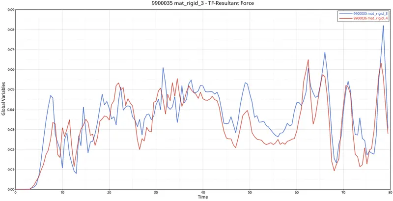
RIGID BODIES- It is varying in nature as the car collides the rigid wall and force transmitted is not linear and the car is also having different components as well.
e) Plotted graph is for INTRUSION
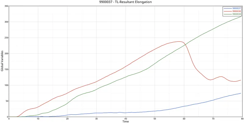
INTRUSION- Spring near B PILLAR changes linearly as b pillar is in direct contact with the rigid body. Spring near FUEL TANK will not somewhat linear. Spring near HINGE PILLAR will first increase and then decrease.
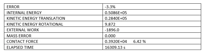
CONCLUSION:--
1) Created section.
2) Bought COG to middle.
3) Learned how to give velocity.
4) Learned how to give Boundary conditions.
5) Learned to create interface & intrusion.
6) Learned how to request output blocks.
7) Learned post-processing.
Link to access the model files-- https://drive.google.com/drive/folders/1_pS0wnoOwNK9MQRJHEp1g14p4p9B4ug-?usp=sharing