Week 9-Creation of 1D Connectors Challenge
AIM:--
1) Creation of 1D Connectors Challenge.
PROCEDURE:--
1) First import the model.
2) Check for Geometry cleanup if required and extract the mid surface.
3) Assign QUALITY CRITERIA.
4) Now Mesh the components using AUTOMESH (F12). Specify Element type and Size.
5) Check for failing elements, if any.
6) Assign CONNECTOR for every components.
WHAT ARE CONNECTOR?
--A connector definition describes the connection between multiple entities at a specific location. Entities that are to be connected are referred to as link entities. The connector location can be defined as a node or node list, a geometric point, a line or line list, a surface, or even as elements or tags. Connections can be created as spot-weld, seam-weld, adhesive, bolts, masses. A realized connector will be considered as the successful representation of CAD model in pre-processing and the connecting parts can be considered as connected.
There are three different states of connectors.
- REALIZED CONNECTORS
- UNREALIZED CONNECTORS
- FAILED CONNECTORS
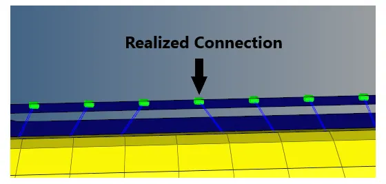
STATE:1 (Realized connectors)-- Succesfull creation of connector will be in GREEN colour.
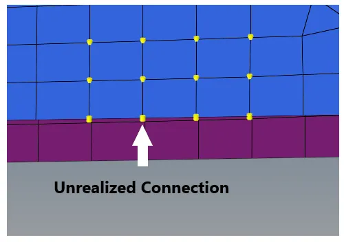
STATE:2 ( Unrealized connectors)-- Unrealized connector will be in YELLOW colour.
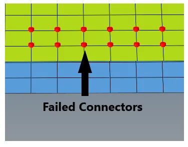
STATE:3 ( Failed connectors)-- Failed connector will be in RED colour.
TYPES OF CONNECTORS:--
SEAM WELD:-- The Process of joining the workpiece which are made of similar or dissimilar materials along a continuous seam is known as Seam weld. In hypermesh, seam panels under connectors will help to represent the Seam weld connection between the components.
Steps to be followed to create Seam - Quad (angled+Capped+L) Weld:
1) Select 2D Connectors Seam option.
2) Now select the location, where the Weld has to be created, by clicking the NODE LIST.
3) Tick the checkbox of RETAIN NODE option, to retain the position of the nodes, while creating and realizing a connector.
4) Specify the SPACING value and select the "comps" option under connect what, in order to create the weld between those two components.
5) Specify the TOLERANCE value, based on the distance between the two components.
6) Select the type as SEAM-QUAD (angled+capped+L)"
7) Click on the CREAT button.

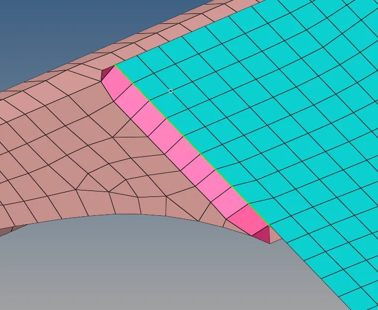
8)Follow the same steps for SEAM-QUAD(angled+capped+T).

NOTE:-
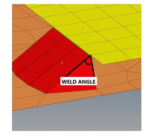
Weld Angle: Angle between the normal projection of the nodes and slant length of the weld element. It is recommended to define weld angles between 0 and 90 degree.
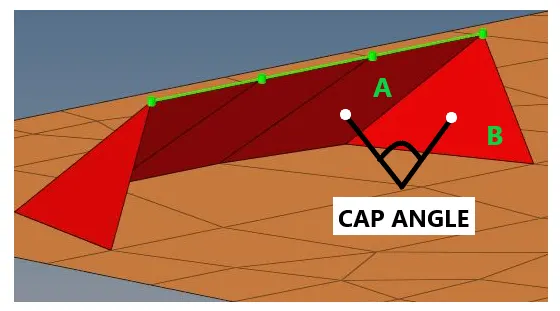
Cap Angle: Angle between the normal of the first slant weld element (A) and its adjacent side element (B). To define seam weld for O to 45 degree cap angle, it
is recommended to select <10 degree and for the 45 - 90 degree cap angle, it is recommended to select >75 degree.
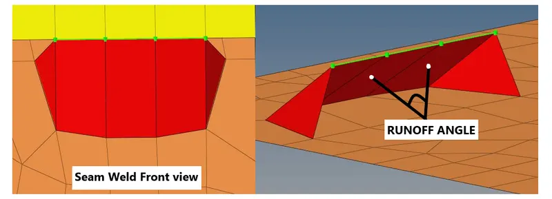
Runoff Angle: Angle between the normal of the first slant weld element and its adjacent weld elements.It is recommended to define weld angles between 0
and 10 degree.
Options to be changed to Realize the connectors:-
1) SPACING value defines the space between each node of the weld element, which should be equal to the Target element size, this will ease the weld element to be created between the components.
2) Only entities within this tolerance can be taken into account for the link detection and the final realization. If the connection entities are away from the search tolerance, seam weld may not get realized.
3) By switching the option from "quad transition" to "remesh", we can realize the connector.
Seam-Hexa Adhesive Weld:-
1) Select 2D Connectors Seam option.
2) Now select the location, where the Weld has to be created, by clicking the NODE LIST.
3) Tick the checkbox of RETAIN NODE option, to retain the position of the nodes, while creating and realizing a connector.
4) Specify the SPACING value and select the COMPONENTS option under connect what, in order to create the weld between those two components.
5) Specify the TOLERANCE value, based on the distance between the two components.
6) Select the type as HEXA (adhesive).
7) Click on the CREAT button.

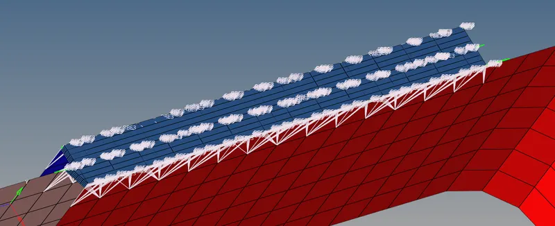
NOTE
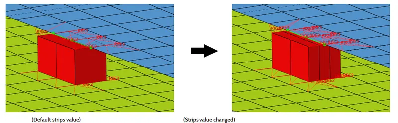
STRIP:- It defines the number of HEXA elements required for along the WIDTH.
COAT:- It defines the number of HEXA elements required for along the THICKNESS.
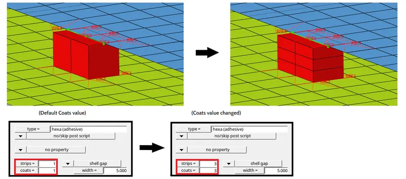
WIDTH:- It defines the continous HEXA weld width in the direction perpendicular to the same dorection.
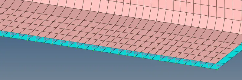
SPOT WELD:--Spot welding is a resistance welding process that is used primarily for welding two or more metal sheets together by applying pressure and heat to the weld area. Heat for the welding process will be obtained from resistance to electric current. Realized spot weld in HyperMesh will represent the connection between the components.
Steps to be followed to create Spot Weld:
1) Select 2D - Connectors SPOT option.
2) Now select the location, where the Weld has to be created, by clicking theNODE LIST
3) Tick the checkbox of RETAIN NODES option, to retain the position of the nodes, while creating and realizing a connector.
4) Specify the "spacing" value and select the "comps" option under connect what in order to create the weld between those two components.
5) Select the number of layers(Number of Components) to be welded, under NUM LAYER option.
6) Specify the TOLERANCE value, based on the distance between the two components.
7) Select the type as WELD.
8) Click on the CREAT button.

BOLT CONNECTION:-- Bolted joints are one of the most common elements in construction and machine design. A connection between structural members made with plates and bolts, as
opposed to a riveted or welded construction. In HyperMesh, we use the RBE2 elements to represent the Bolt connection, since it has more stiffness.
Steps to be followed to create Bolt connection:
1) In order to create a Bolt connection, if we had hole present in the components, we have to locate a centre node as shown below:
2) Now click on the 2D Connectors -BOLT option.
3) Under location select the node, which we created already to establish the bolt connection.
4) Then select the COMPONENTS option under connect what, in order to create the weld between those two components.
5) Select the number of layers to be welded, under NUM option.6) Specify the TOLERANCE value, based on the distance between the two components.
6) Select type of BOLT.
7) Click on the CREAT.

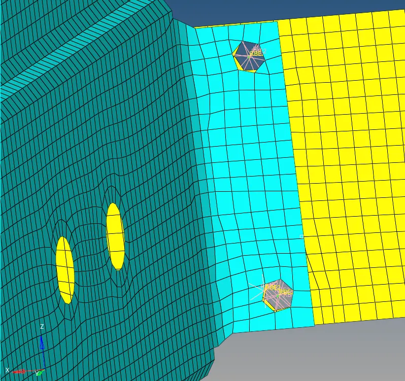
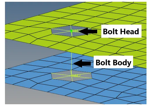
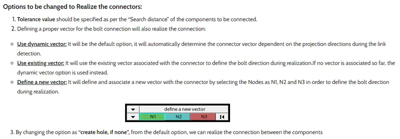
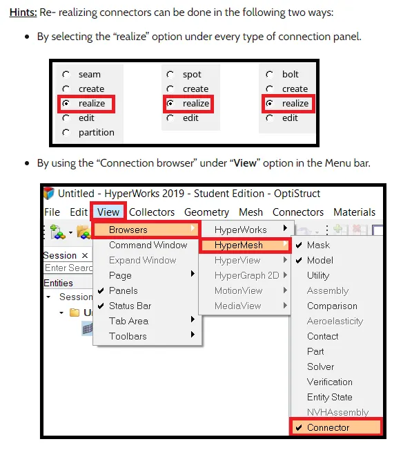
HINT:-- HOLE WILL BE CREATED IN FEA MODEL ITSELF, NOT IN THE SURFACE OF COMPONENT.
FINAL MODEL--
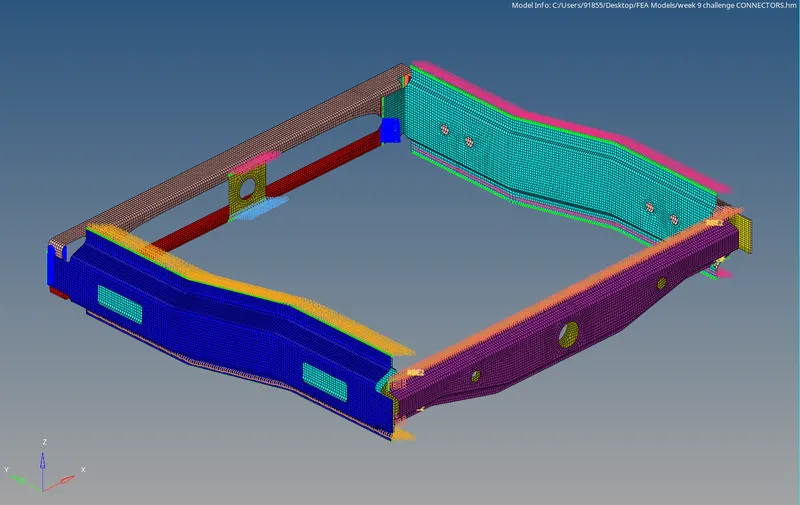
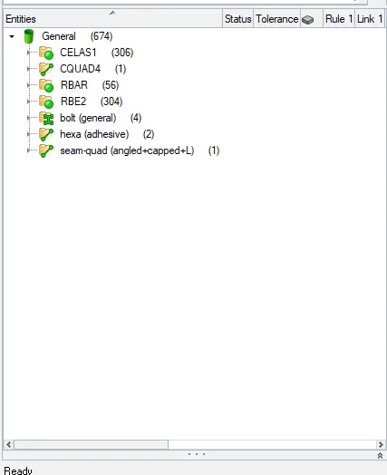
- GREEN COLOUR SAYS THAT ALL THE CONNECTORS ARE REALIZED SUCCESSFULLY
CONCLUSION:--
1) Applying differents types of connectors and their uses.
2) Appropiate action to debug the unrealized connectors.