Assignment 6-Frontal Crash Simulation Challenge
Aim: For the given car front (BIW component) we need to perform the crash analysis aganist the rigid wall for the requests given below.
Requests:
1)Check the unit system and either follow (Mg mm s) or (Kg mm ms).
2)Create the appropriate interface ,fraction 0.2 and recommended parameters.
3)Make sure of no penetrations and intersections
4) Correct the rigid bodies if any issuses.
5)Create rigid wall with the friction 0.1
6)Compare the model weight with full scale 300k nodes model and use added masses to reach target weight 700kg while getting CG about the required range.
7)Initial velocity 35mph.
8)Use model checker to ensure good quality.
9)Time step:0.5 to 0.1ms(Microseconds).
10)Run 80ms
Outout Requests:
1)Sectional force in the rails at location of indicatednode 174247.
2)Axial force received on the rails from the bumper.
3)Shotgun cross sectional forces.
4)A-pillar cross-section.
5)Acceleration curve received on accelerometer at base of B-pillar (On B-pillar rocker).
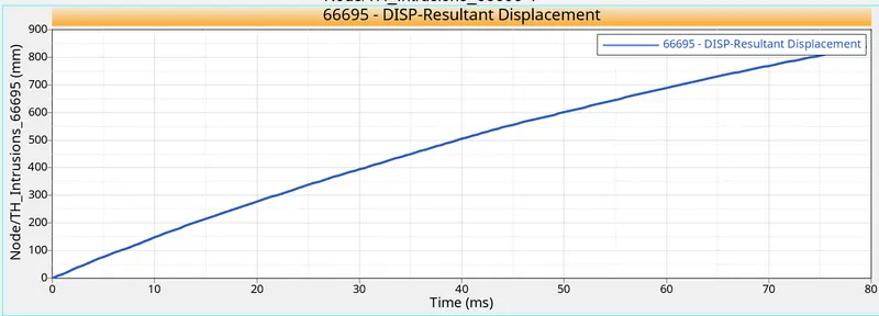
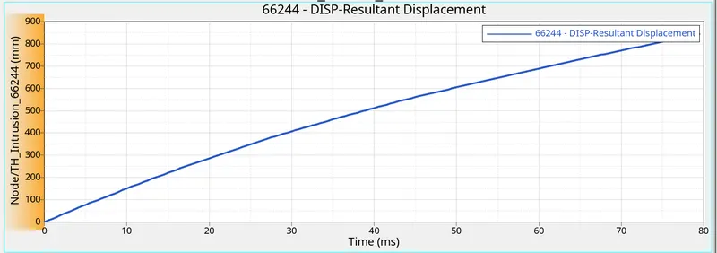
6)Intrusions on the dash wall 66695,66244
Here why Explicit analysis?
It is the dynamic approach is most helpful in solving high deformation and time dependent problems.
Dynamic response of a structure due to stress wave propagation, impact or rapidly changing time-dependent loads. Momentumexchange between moving bodies and inertial effects are usually important aspects of thetype of analysis being conducted. This type of analysis can also be used to model mechanical phenomena that are highly nonlinear. Nonlinearities may stem from the materials,
(hyperelasticity, plastic flows, failure), from contact (high speed collisions and impact) and
from the geometric deformation (buckling and collapse). Events with time scales of less than
1 second (usually of order milliseconds) are efficiently simulated with this type of analysis.
Based on all these conditions the user will select an explicit solver to solve the analysis. Typical
examples of explicit analysis are crash analysis, drop test, bird strike, fan blade out…etc.
Procedure:
1.Check the unit system and either follow (Mg mm s) or (Kg mm ms): Once the 0000.rad file is imported using the file >import the solver deck select the 0000.rad file and import and the solver tab select the Begin card and check the unit system as shown below.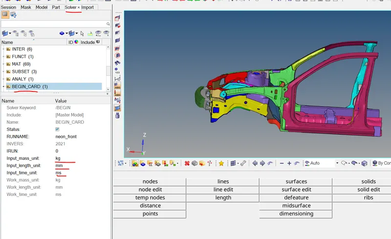
fig: unit system check
2)Create the appropriate interface ,fraction 0.2 and recommended parameters: As per the theory says Interface Type-7 Recommended for the Crash applications as shown below. In Hypermesh,from the solver tab > Right click ,create and select the INTER and select the TYPE_7.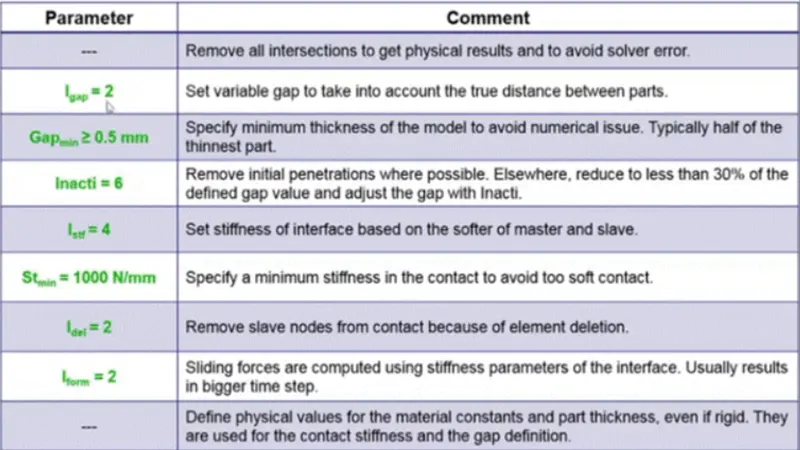
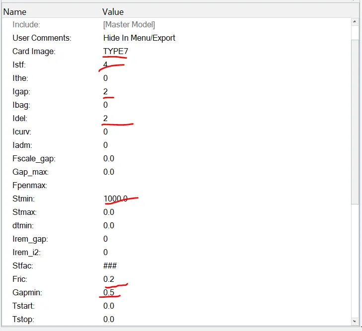
I have entered the mentioned the values above .
3)Make sure of no penetrations and intersections :
Make sure we must avoid the penetrations before we proceed to the simulation if not it throw as error .if the penetraions are minimal it will start simulation when we try take the contours like stress and contact forces before the deformation start its show some value which we dont want. Using Tools >penetration check it opens the penetration window in the entity type is Groups(contacts) and groups select the contacts then checks since it has no penetration exist and it throw as No penetration found as shown below.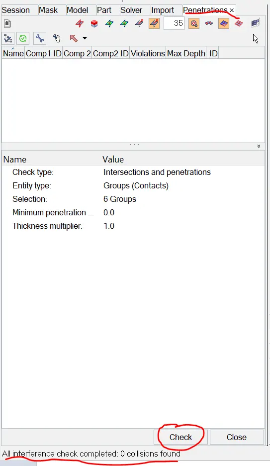
4) Correct the rigid bodies if any issuses:
when we go to Tools >model checkers >radioss ,window opens with INFO,ERRORS,WARNINGS when we do RUN in the status bar shows if any errors or warnings as per the theory the warnings are not a issue errors causes problem we need to fix the errors. As shown below.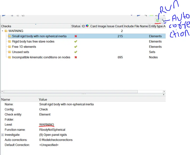
5)Create the Rigid wall with friction 0.1:
switch the model tab and right click >create >select the rigid wall ,once created click on the rigid wall enter the suggestion as shown below.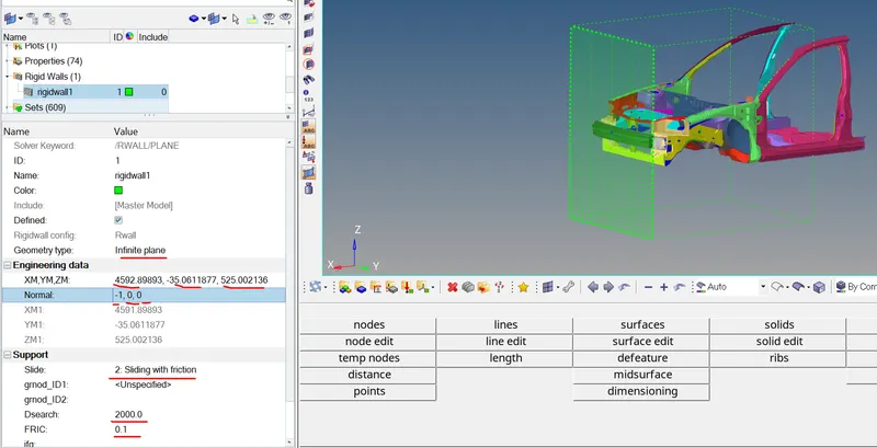
from the image in the rigid wall card marked suggestions we need to feed .the created rigid wall shown in the GUI.
6)Compare the model weight with full scale 300k nodes model and use added masses to reach target weight 700kg while getting CG about the required range:
when before proceeding to mass adition if we take a look at the mass details of the model is Tools >mass details >click mass ,inertia the details as shown below.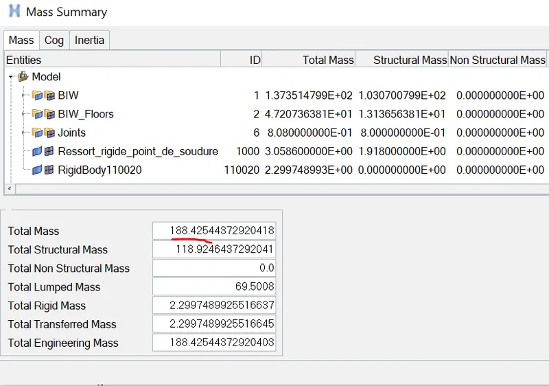
if we take look at the total mass before the addition which is 188.42544 so for this weight we need to add mass which will get balanced with the given mass 700kg,which means out of 700 188.42 kg mass already exist so 700-188.42=511.58kg we need to add mass so that it balanced to 700 kg and same way the CoG point also shift at back of the driver seat. In the solver browser right click >create >ADMAS ,the entity is created marked the changes we need to feed.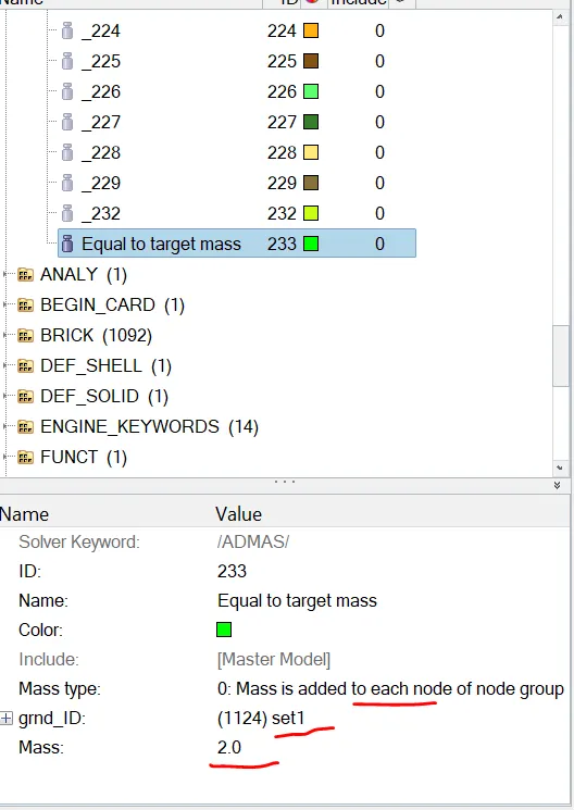
here the mass type is 0 which is mass is added to each node of node group and in the grnd_id:select the nodes which is each node carring weight of 2kg and add of mass which is our interest here i have added masss as shown below so that cog is moved back as shown below.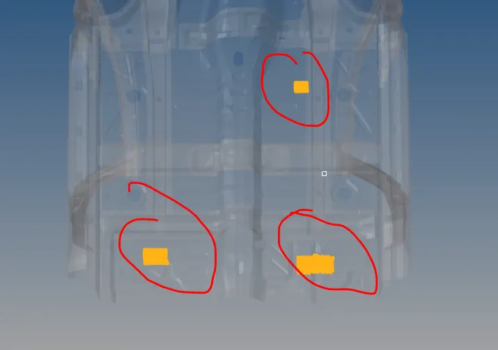
Fig:mass added at the marked places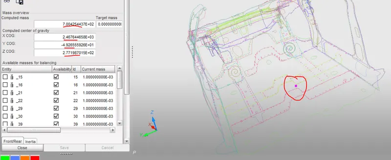
from the above image if we see the cog is moved back which we want actually and computed mass is 700 kg which is desired weight.
7)Initial velocity 35mph:
In Boundary condition initial velocity is very importent the given velocity in the mph to mm/ms use the online tool 15.64 mm/ms.
in the solver tab right click >create >select the boundary conditon (since the intial velocity related to boundary condition ) >select the INIVEL ,the entity is created in the solver tab as shown below feed the values requestred as marked in the image.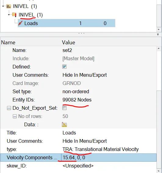
if we see below the whole nodes of the model as shown below and initial velocity is applied to all nodes thats why selected nodes shown. when simulation start the model come and hit the wall with the velocity of 15.64mm/ms.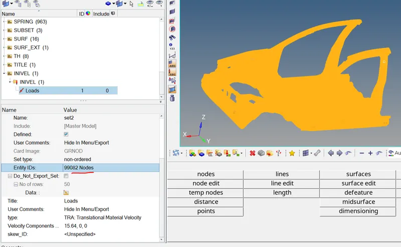
8)Use model checker to ensure good quality:
Go to tools > model checker > select the radioss block, model has no errors and only warnings but warnings does not effect the simulation. and in the satus bar showing ready.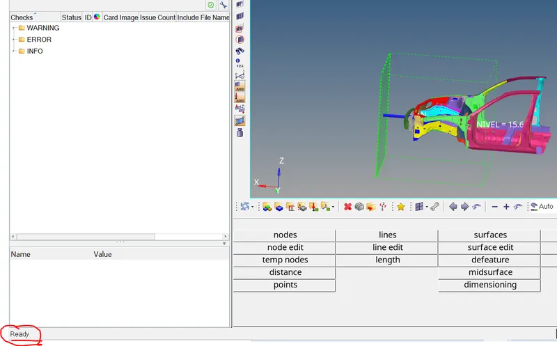
Fig:No errors shown
9)Time step:0.5 to 0.1ms(Microseconds):
from the model tab >select the cards >Select the ENG_DT_NODA in the select the value of the Tmin=0.4(Given condition is 0.5 to 0.1 we can also take valve in between ) and ENG_RUN set the runtime 80ms. as shown below.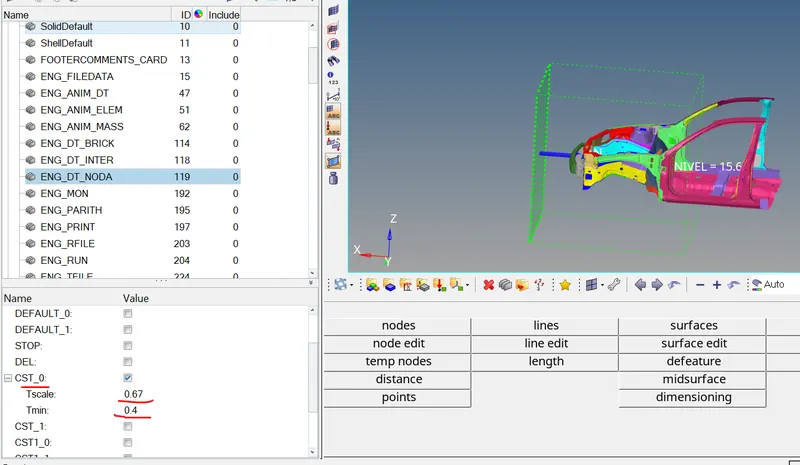
Output request:
Sectional force in the rails at loaction of indicated node 174247:
Advantage of the section creation is how much force is transmitted through the particular area when it deformed as part of that 6 nodes has been identified from the video based on that we will create the Moving local coordinate frame/skew(For the skew the origin is fixed and for the frame the origin is changing with the node ) created . Defining this are the the deformation we could see globally but locate particular areas how much force is transmitted through particular area by creating the local frames .
Create the Frames:
in the solver browser right click >create the >section once it is done again in the solver browser right click >create >Frames,it allows to select the nodes locally it is moving frame select the node of reference suppose we want the on A-pillar so N1=orgin node N2=Axis node, N3=Plane ,select the nodes and create it creates the local axis on A-pillar. then go to section entity and open the card , the card the selct the N1,N2,N3 this are axis of the force in that direction and selection of this based on the global axis and in the card of the section we have to feed N1,N2,N3 and the Frame Id and Two row of the elements and delta T value(advantage of this is it start saving the sectional forces values minimum values for this is 0.1).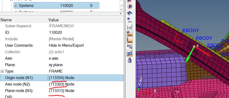
Fig: Moving frame(local co-ordinate is defined
Create the section:
To create the section we need to feed the values as shown below and selection of the 2 row of the elements as shown in the GUI as swell.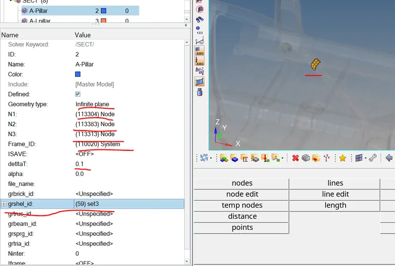
The selection of the nodes with reference to global and and grshel_id=select the 2 row of elements.
And create the Time History for the each section to do that in the solver tab right click >create >TH>section and card requires as shown below. here the Entity ID is to select is section (A-Pillar_LH&RH).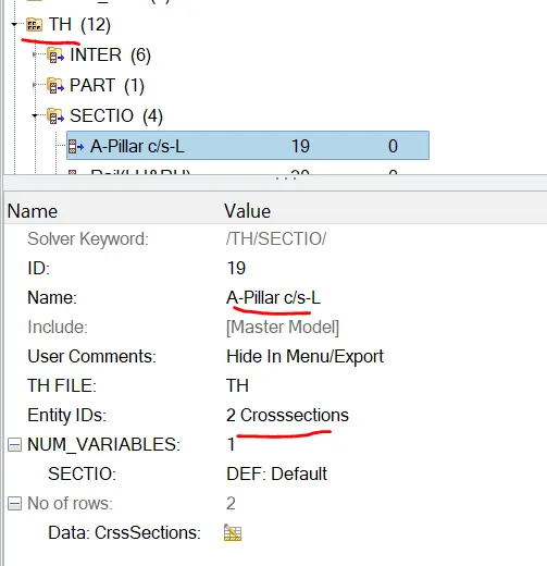
Like the steps mentioned above i have followed the same to create the local moving frame and sections,Time history.
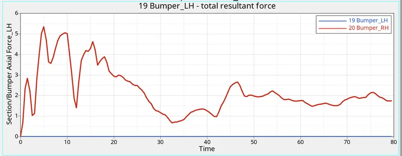
Axial force received on the rails from the bumper:
For here also i follwed the method is created the moving frame and sectional force since the type of the method is not mentioned so i follwed the same as above.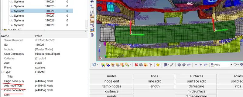
Created the Local frame and Section and two row of elements .
Acceleration curve received on accelerometer at base of B-pillar (On B-pillar rocker):
As it mentioned that we need to create the Accelerometer we need to place at on base of the B-pillar rocker. To do that in the solver tab right click >create >ACCEL once selected on the name entity id created ,in the card we need to select the node where we want to place the accelerometer as shown below. now we have created on the one side same way we need to create the other side as well. 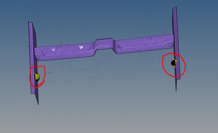
Fig: accelerometer created on rockers.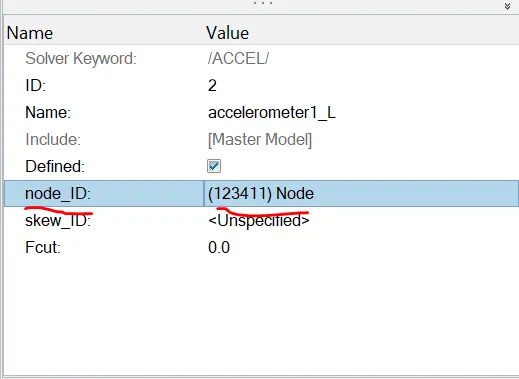
Fig:Selected node where the accelerometer placed
here only node selected where we accelerometer needs to be placed and here card there is skew _id also avliable our interest is to see the readings globally thats why we have not selected the Id.
Intrusions on the dash wall 66695,66244:
Intrusion is where the it experiencing the more the force in the challenge there were two nodes mentioned ,here i have follwed the created the local moving frame with reference to two given nodes,as shown below. To find the node select the Display the number option select the node by given id which is 66695 and 66244 enter and display check box and> click ON. once the it displayed i added temp node over there. To define the local frame on the channel create >frame >we get the chance to select the nodes N1,N2,N3 from the model.N1 is origin and N2 is select the given node while going for node 66695 select the N2 as the 66695 as shown below.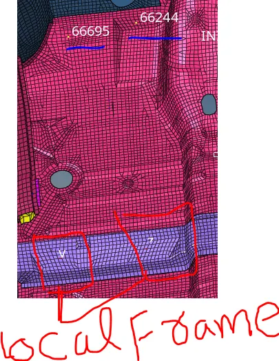
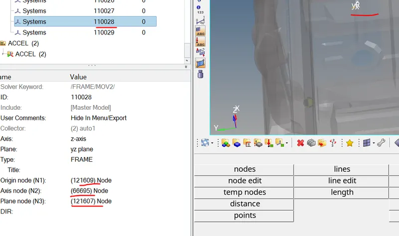
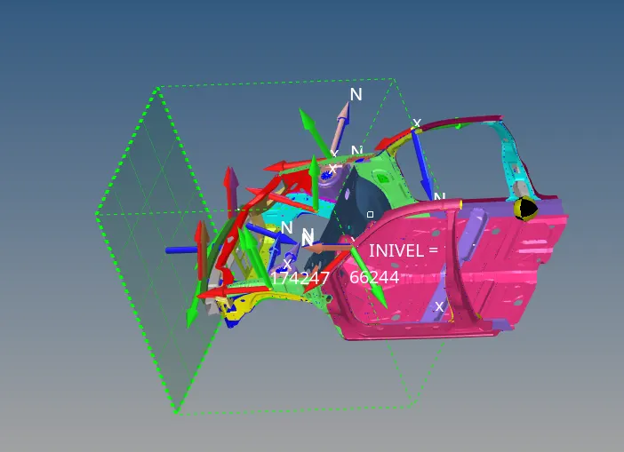
fig: preprocessing model before proceeding to solving
All the prepropressing which is done on based given statements and once this done we can proceed for the solving and post processing.
from the main menu page select the Analysis >radioss >set up the require feeds like file save and -nt 4.>radioss.
Post-processing of the model: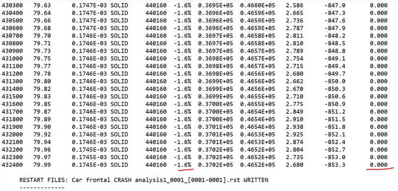
Observations:
Elapsed Time = 18693.72s
Total Number of cycles = 432447
Starter +Engine file =18698.77s
Mass Error = 0
Energy error = -1.6%
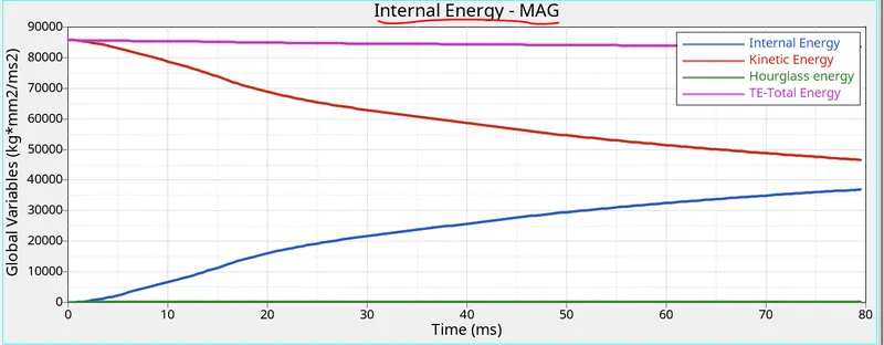
1)As per the theory the energy error the error must be negative and decreasing so ideally the error should be at most -15% and -5% .And the mass error is less than 2%. from this both are satisfied we can proceed further.
2) If we look at the internal ernergy and kinetic enrgy ,hour glass energy,contact enrgy. When The deformation start the internal enrgy increase because the the elements with the neighbourings start deforming with absorbing energy when it reaches to 80ms the internal energy increase. We can also observe that the hour glass energy is zero because we have used the QEPH intergrted elment formulation it avoids zero strain deformation. And the kinetic energy decrease and which is deformation is inversely proportional to kinetic energy ,in the graph as the deformation increase the kinetic energy decrease because the model is moving normal to the wall it will not cross the wall and velocity decrease and kinetic energy decrease. And here inertia also comes it resistance to change the velocity when the deformation happening the because of the friction between elements the velocity changes.
3.) In the sectional force for the component A-pillar(LH&RH),Rail(LH&RH),Bumper(LH&RH),Short gun(LH&RH),the compnents at the front will be effected 1st and let say at first initial deformation the bumper get effected first and And the the next componet that experience the deformation is for the bumper theRH the peak force is 5KN at 5ms the if we convert the 5kg to KN (5*9.81=49.05) and for the LH 4.2KN and 5.6 ms
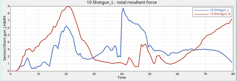
4)Shoth gun _RH= 9KN at the 22ms peak value
Short gun _LH = 8.8KN at the 42 ms peak value
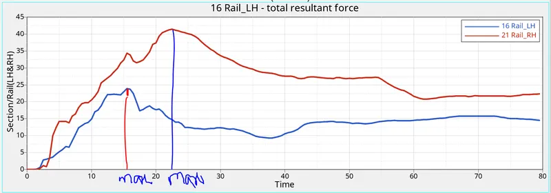
5)Rail _LH = 22KN at the 17ms peak value
Rail _RH = 42KN at the 23ms peak value
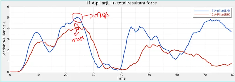
6) A-pillar _LH = 4KN at the 22ms peak value
A-pillar _RH = 5KN at the 23ms peak value
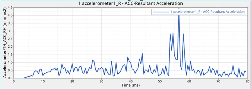
7) Peak Acceleration result for RH=4.5mm/ms^2
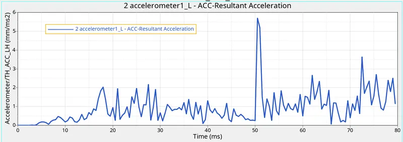
Peak Acceleration result for LH = 5.7mm/ms^2
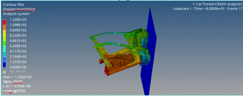
8) The Intrusion displacement for 66695 and 66244 and in this i have measured the distance between which is given node and opposite to the node and distance taken before and after the didplacement of the node after subtraction of the values i got for the 66695 the displacement value is 67 and 66244 the displacement value is 106.75 .the node 66244 which is at the front get the more displacement from the values i have got.
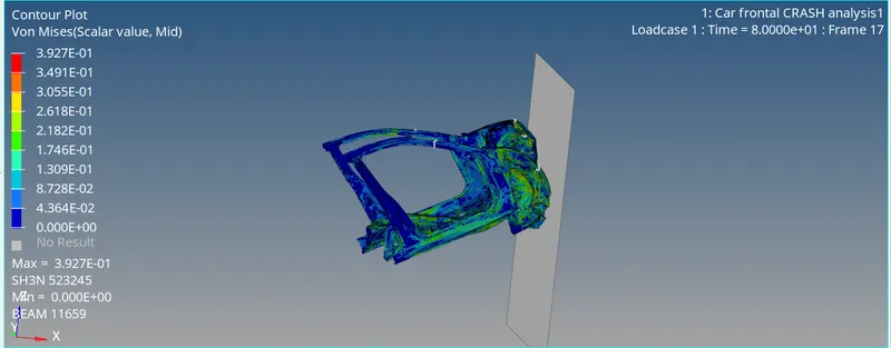
9) We observe that right side portion we could see major deformation compared to left side because the mass is added to right side to get it balance the COG at the back of the driver seat .From the above results in case of the short gun the RH side at 22ms it experiencing the peak force and the LH side the experienced at the 42ms
10)In the Accelerometer graph it measures the rate of change of velocity at every second the change in the geometry thats why there is ups and downs in the graph. In the starting deformation we will see small change because of small deformations and it reaches to max deformation we could see peak change. There is different peak acceleration change for both LH and RH
Result:
For the given car front (BIW component) , the crash analysis aganist the rigid wall has performed for the requests mentioned above.