Week 8
Aim: For the given sheet metal component use morphing Technique to change the deign or shape of the component
Theory: Here the the given component is sheet metal we need to apply the morphing technique in particular areas where the changes are required. Here The changes we do based on the Parent geometry which is change in length and change in shape. we use the morphing in cad design or FE to compare the results form the Exist design and morphed one based on that we proceed further
Procedure:
1.import the cad geometry
2.Morphing
1.Import Cad Geometry:
File >Open>select the respective cad file….
Once cad file imported change the length to 1mm to refinement of the cad and do topo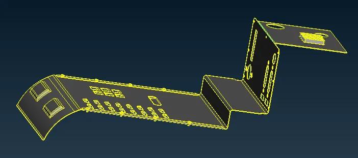
Fig:Topo and Oriented Model
2. Morphing:
Here we use free -free morphing method:
We can morph the model any direction that we want so that gives it in new shape and size.this also called basic morphing or ortho morphing . because here we not giving any numerical input .based on the selected direction we are changing its length and size approximately. Here we box type selection for morphing the entities within the cell only gets changed its length and shape,to create the box selection .
Operation:
Goto Morphing Module>Boxes >New,ortho>select the entities and middle click the box is created in green colour and again middle click to exit.
To move the Grid Points in desired direction , Box morphing in the same Module> select the Move and select the grid points and middle click its starts moving the entities within the box and middle click to stop movement and exit .
Here the Coordinate axis Aligned with the Global Coordinate Axis. And to check the Morphing in database we On the Morphing Name One Row created . Here we can also delete the Morphing Box which are not required
Morphing module>Boxes>delete>and select the green colour box and middle click
Here below i haved mentioned what changes has been done in Actual Cad to Morphing Cad As Mentioned in the challenge.
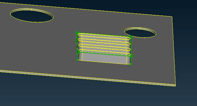
Fig:Actual Design of the Cad with Morphed Box
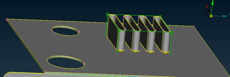
Fig:Morphed Ribs
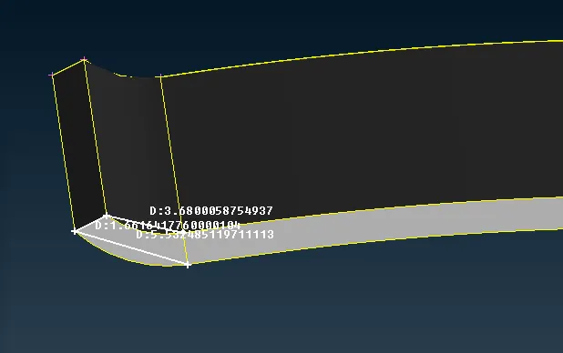
Fig:Actual Cad Face
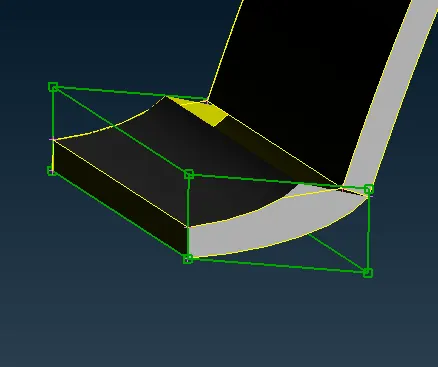
Fig: Morphed Face
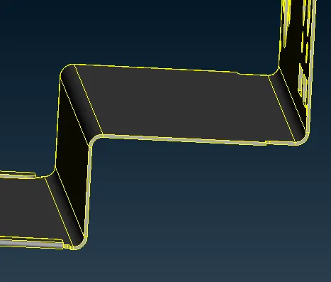
Fig:Actual Cad face
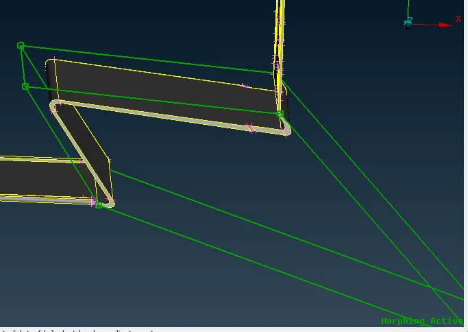
Fig:Morphed Face
Fig:Actual Cad
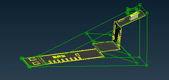
Fig:Entire Cad Morphed
Learning Outcomes:
1.From this challenge i have learnt waht is Morphing and byusing how we can change the shape and size
2.Method of the Morphing(Free-Free morphing)
3.Procedure to Apply Morphing(Can be Applied to both Cad and FE Models)
Result:
For the given sheet metal component morphing Technique has been used to change the deign or shape of the component.
Model Link:
https://drive.google.com/file/d/1vKlKVG8v_4Rpth5mW672v3R9e0IpiOKh/view?usp=sharing