Project 2
PREPROCESSING OF VEHICLE REAR SUSPENSION
AIM:For the given cad geometry of rear suspension do the geometry check and solid meshing and proper mid surface and shell meshing as per the quality criteria given below.
Quality Criteria For the Tria Elements(Tyre and Rim):
|
s.no |
Quality Criteria |
Value |
|
1. |
Target Length |
6.5 |
|
2. |
Minimum Length |
5 |
|
3. |
Maximum Length |
10 |
|
4. |
Skewness |
45 |
Quality Criteria For the Mixed Elements (For Midsurface)
|
s.no |
Quality Criteria |
Value |
|
1. |
Target Length |
4 |
|
2. |
Minimum Length |
2 |
|
3. |
Maximum Length |
6 |
|
4. |
Aspect Ratio |
3 |
|
5. |
Warpage |
15 |
|
6. |
Skewness |
45 |
|
7. |
Jacobian |
0.7 |
|
8. |
Minimum Quad Angle |
45 |
|
9. |
Maximum Quad Angle |
135 |
|
10. |
Minimum Tria Angle |
30` |
|
11. |
Maximum Tria Angle |
120 |
Quality Criteria For the Tria (For the other Components)
|
s.no |
Quality Criteria |
Value |
|
1. |
Target Length |
4 |
|
2. |
Minimum Length |
2 |
|
3. |
Maximum Length |
6 |
|
4. |
Skewness |
45 |
Common Quality Criteria For the Tetra Elements
|
s.no |
Quality Criteria |
Value |
|
1. |
Tet Collapse |
0.2 |
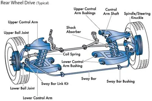
Fig:Suspension System and Along With Names
Theory:
The given cad geometry is vehicle rear suspension which are having number of components like suspension rod,suspension spring (helical),Base Plate,Ball Joint,Tyre,Rim. This components has different thickness as per geometry .We use different methods to model the rear suspension. We have Thumb Rules like if the thickness of the component is grater the thickneess 5mm we use the solid or volume meshing and wherever the thickness below the 5mm use the shell meshing. We also use the 1D meshing for the Helical spring.Use the Appropriate Connections which is Part of the Modelling
Procedure:
1.Geometry check
2.Mid Surface ( Thickness less then 5mm)
3.Shell Meshing(2D Mesh)
4.3D meshing (Thickness Above 5mm)
5.1D meshing(Helical Spring or Torsional Spring)
6.Connections
1.Geometry Check:
Import the Cad Geometry From the Local Folder File ˃open ˃ Select the Cad File .once the Geometry is in GUI Change the Length is 1mm or 2mm depends on the Geometry, Mesh Module ˃ Perimeter ˃Select the Length Option ˃and select the Entire Geometry length as 1mm and same for the Macros As well. And Apply Topo Entire Geometry After that Model look like shown Below.
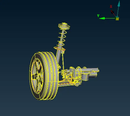
Fig:Topo Model
2.Mid Surface:
Measure the Thickness which comes below the 5mm at the Random Places and isolate the component and Do the Geometry Check and offset the Faces,As shown below.
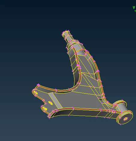
Fig:Midsurface Generated
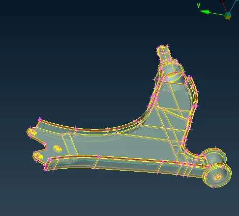
Fig:Mid surface showing in PID mode
3.Shell Meshing(2D Meshing):
Before Apply the Shell Mesh we need to Enter the Quality Parameters As shown Below.
And Also in Utilities ˃ Select the the Mesh Parameters Enter the Target Length and Minimum and Maximum Lengths and ˃ok.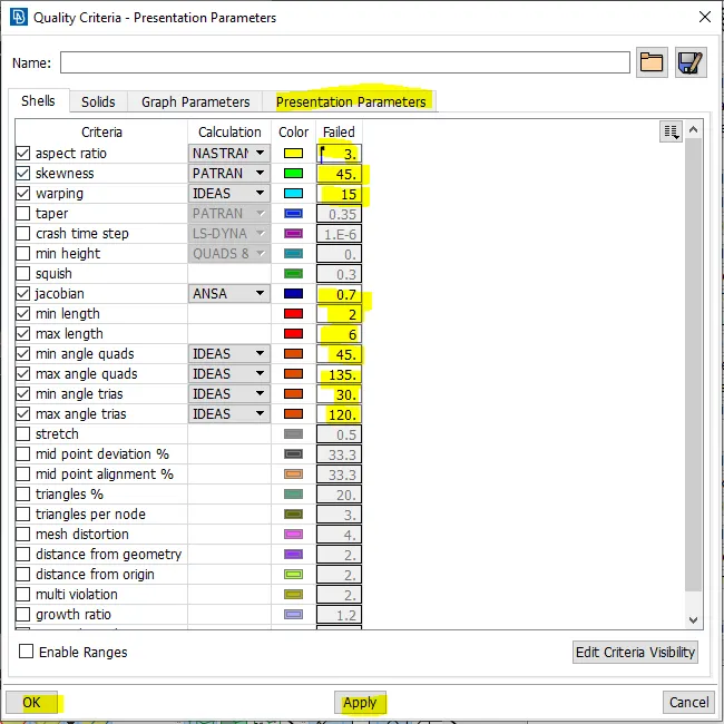
Fig Quality Criteria For the mid surface base plate(2D mesh)
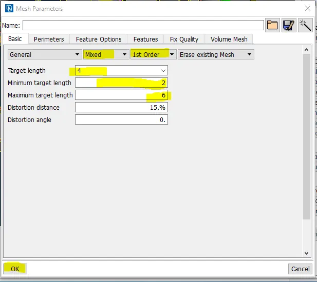
Fig:Mesh Parameters (base palte 2D mesh)
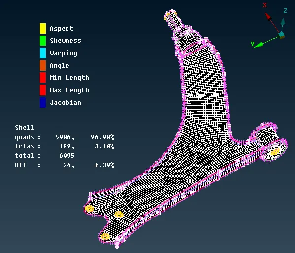
Here the component with less off elements which are minimum length criteria and we have to avoid the maximum length which are not acceptable.
4.3D Meshing:
First we have to apply 3D meshing we have to measure the thickness which satisfy the thumb rule which is grater than 5mm.
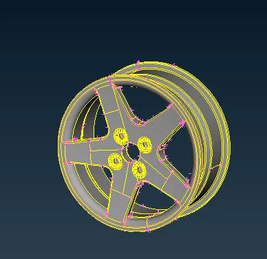
Fig:Disc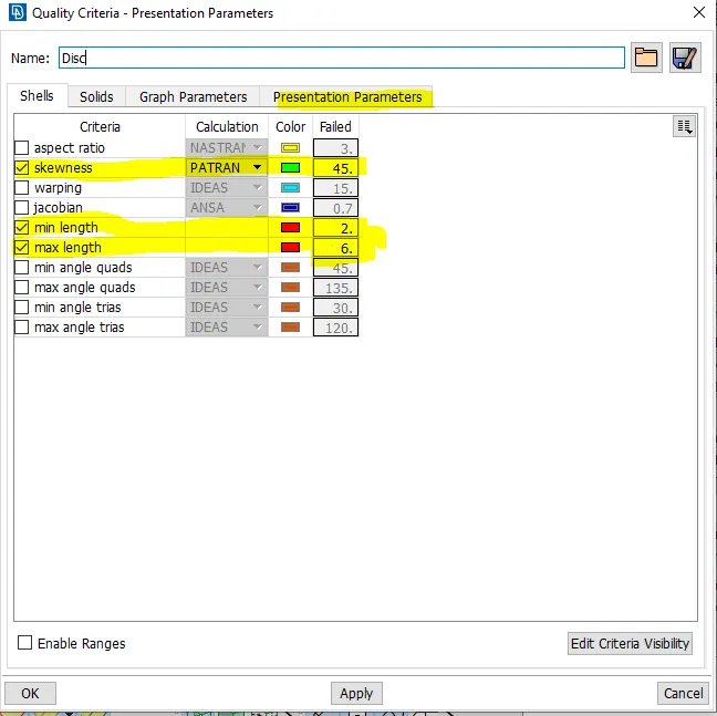
Fig:Disc Quality Criteria
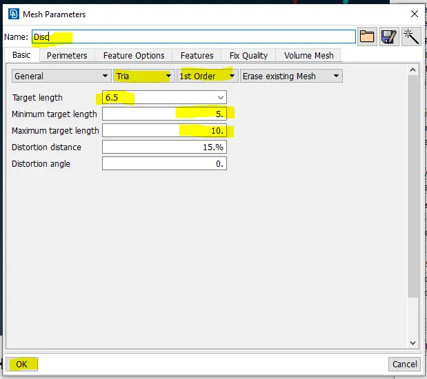
Fig:Disc Mesh Parameters
For the disc component we have used the volume or solid meshing because the thickness grater the 5mm and before we generate the volume we need to apply the surface meshing but here we have to use mesh type is tria nd ortho tria and quad percentage 0%.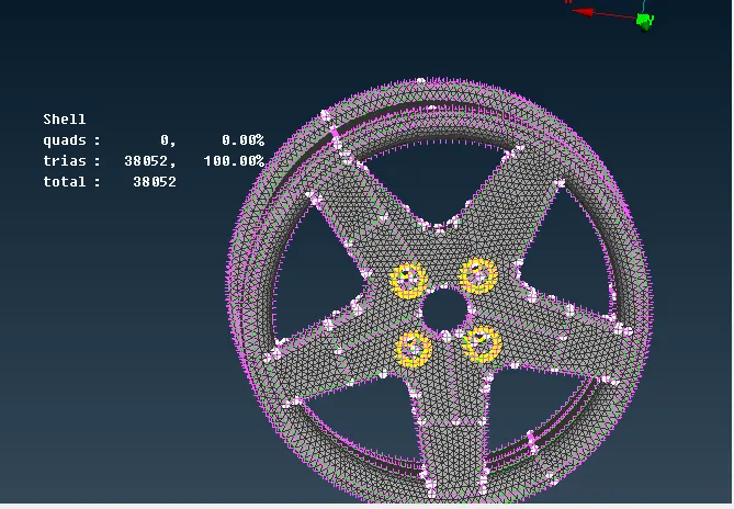
Fig:Meshed Disc Component
once surface meshing is done we have to generate the volume for that we need to define the volume ,in Vmesh˃define˃ Auto or manual select the entire the geometry and ok. In the list(Vmesh˃list˃it will show the name and PID and status Unmeshed ˃right click on the Unmeshed and from the options list select the Remesh˃ and select the Algoritham(i have used Tetra rapid)˃ok. To check the volume generated or not switch of the CAD it will only show Volume. As shown below.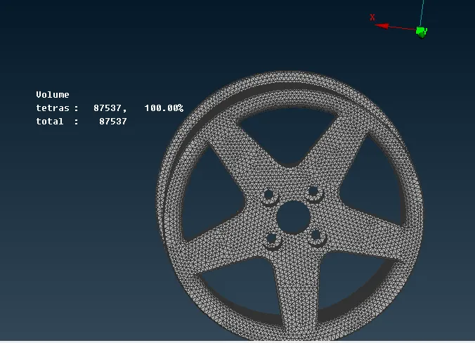
Fig:Volume of the disc
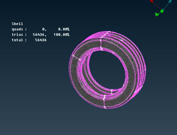
Fig:Tyre
once surface meshing is done we have to generate the volume for that we need to define the volume ,in Vmesh˃define˃ Auto or manual select the entire the geometry and ok. In the list(Vmesh˃list˃it will show the name and PID and status Unmeshed ˃right click on the Unmeshed and from the options list select the Remesh˃ and select the Algoritham(i have used Tetra rapid)˃ok. To check the volume generated or not switch of the CAD it will only show Volume. As shown below.
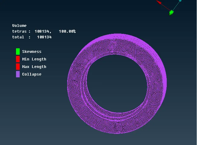
Fig:Tyre Volume
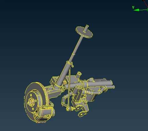
Fig:Suspension Assembly
Here the the suspension Assembly which are having different PIDS like brake calliper,brake drum,Ball joint Rod, with different thickness .Here i have used individual component and generated volume and i have used the Tetra Rapid Algoritham.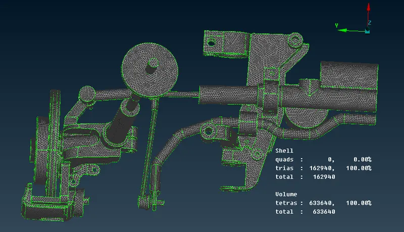
Fig:Volume Generated Suspension Assy
The complete suspension Assy We have to use thesame procedure which is surface mesh and define it as volume and use the Algoritham to generate the volume. I have found 28 components in list as shown below.
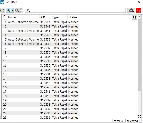
Fig:Volume list with Algoritham
5.1D Meshing:
1D meshing we apply to torsional springs or helical shapes before that we have to use the curves middle option in TOPO module˃cuves˃middle option,the entire spring we have to take and use connect option make it as single curve. In nastran˃select CBAR˃select the entire curve and middle click it will ask for node orientation select the node ˃the property page open˃ in the A we have to select the circle and enter the radius˃ok
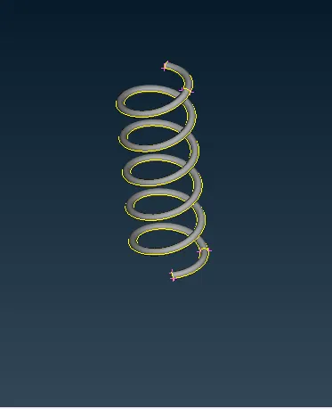
Fig:Suspension Spring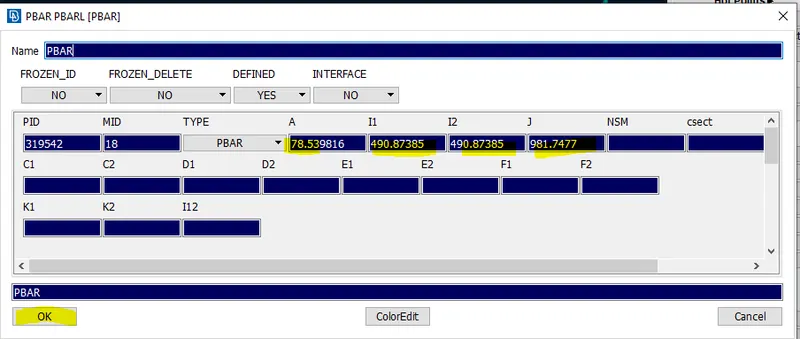
Fig:CBAR PROPERTY CARD
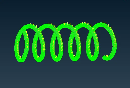
Fig:In Pid mode 1D meshed spring model.
6.Connections:
Connections are the part of modelling we have to give the connections wherever is required like bolt connections and seam weld connections as shown below.
a)Seam weld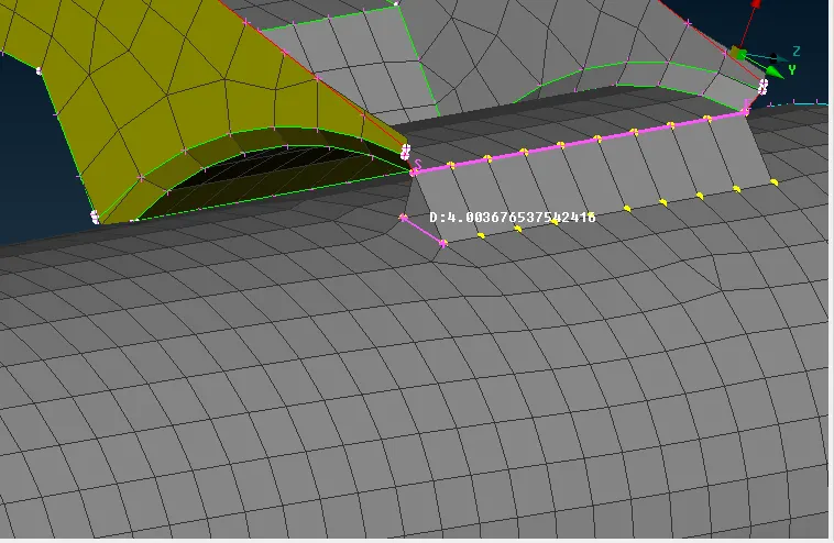
Fig:Seam Weld Connection
to make the seam weld connection we have to convert the curve to seam line and in the connection manager we have to give data as shown below.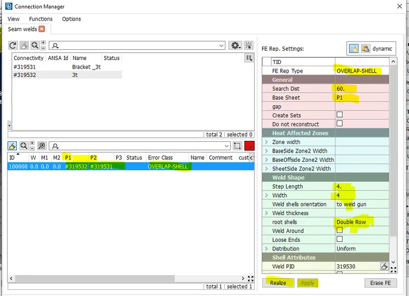
Fig:Connection Data card.
b)Bolt Connection: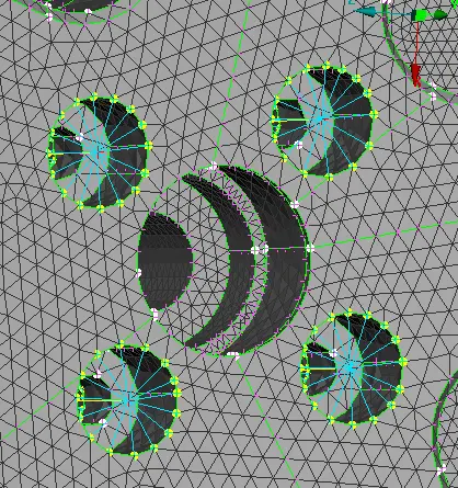
Fig:Bolt Connection
Here i have used the RBE2˃many node and 2node connection to entire bolt connection. and i have made the connections wherever is required.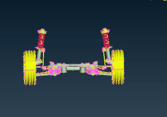
Fig:Mirrored the component
Here i have used 3 points to mirror the component.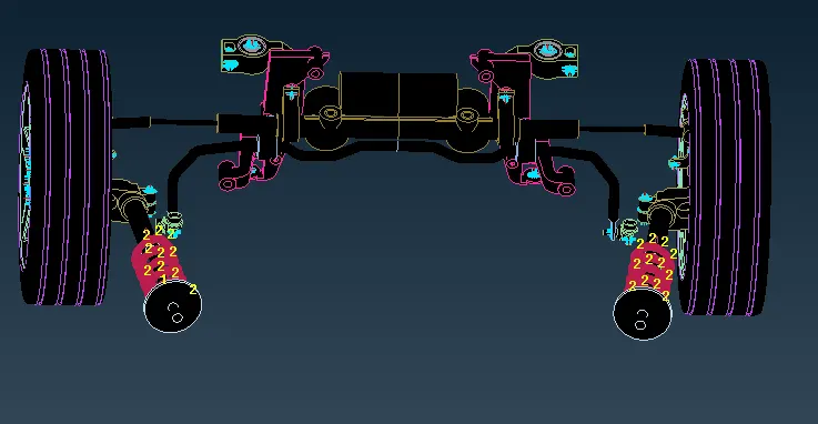
Fig: In PId Mode
Learning Outcomes:
1. I have learnt the modeling
2. i have learnt Techniques of the 1D,2D,3D meshing
3.Connections and types and where do apply connection like blot and seam weld
Result:
For the given cad geometry of rear suspension the geometry check and solid meshing and proper mid surface and shell meshing has been done as per the quality criteria mentioned
Here below i have attached the rear suspension model link:
https://drive.google.com/file/d/1qWKoluv80bkILeizObqKnsTRxblAFYe6/view?usp=sharing