Assignment 7-Side Pole Crash Simulation Challenge
Aim: Perform the side pole crash test on BIW component of passenger vehicle using Hypermesh tool , Radioss solver.
The given requests to check in the model are shown below.
1)Check unit system and either follow (Mg mm ms) or (Kg mm ms).
2)Create appropriate interface ,friction 0.2 and recommended parameter.
3)Make sure of no penetration and intersections.
4)Create the rigid wall with friction 0.1 as per reference model.
5)Compare the model weight with reference model and use added mass to reach target weight 700kg while getting the CG required range.
6)Initial velocity as shown in picture.
7)use model checker to ensure good quality.
8)Time step :0.5 to 0.1 microseconds.
9)Run 80ms.
Outrequest:
10) sectional force in the cross member.
11)INtrusion at B-pillar ,Hinge pillar and fuel tank region. Provide recommendation on what can help to reduce fuel tank intrusion.
12)Peak velocity of inner node of the door.
Import the FE model:
Import FE model using import solver deck option > select the input starter file (0000.rad ) >and import. As shown below.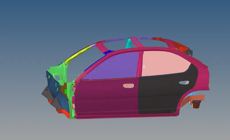
Fig: Imported FE model.
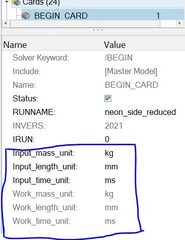
1)Check unit system and either follow (Mg mm ms) or (Kg mm ms):
Two ways we can do this by open the 0000.rad help of Notpad and in the model tab cards >begin cards we can also come to know, as shown below.
2)Create appropriate interface ,friction 0.2 and recommended parameter:
From the model tab > select the groups the given model has default contact interface which we dont want and i created using in the solver tab right click create >interface >Type_7. The type _7 contact interface is recommended for the crash applications so we can edit the type7cardwithrecommendations as shown below .
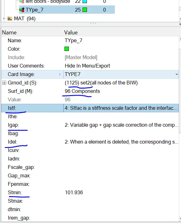
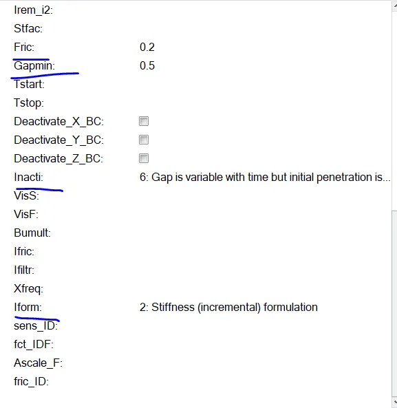
The master and slave node selection is for the slave node selected the all nodes of the BIW and for the master all the components selected.
3)Make sure of no penetration and intersections.
From the Tools >penetrations check,when selected this new tab opens on the name of penetraion and intersection check,in the card we need to select the groups and check if any penetrations it shows.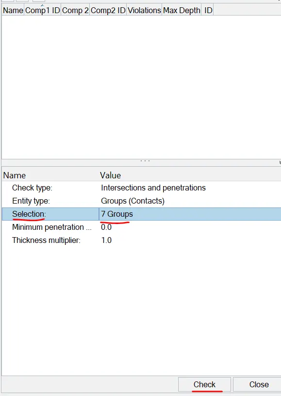
Fig:No penetrations
4)Create the rigid wall with friction 0.1 as per reference model:
we need to create the rigid wall and the here the geometry type is cylinder. Using in the solver tab right click create >Rwall,plane >ok. In the card geometry card is Cylinder and edits to be made as shown below.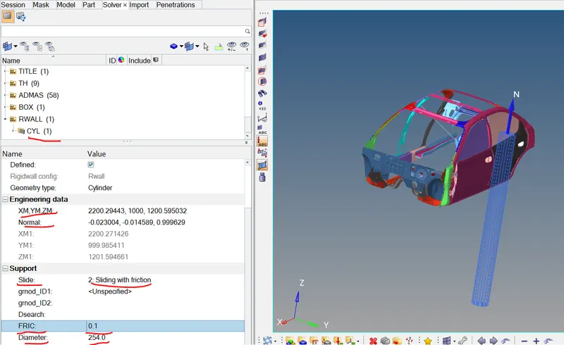
with help of the edits pole created with the standard Diameter as per the FMVSS standards which is 254.
5)Compare the model weight with reference model and use added mass to reach target weight 700kg while getting the CG required range.
before the mass addition the overall weight of the structural BIW is as shown below.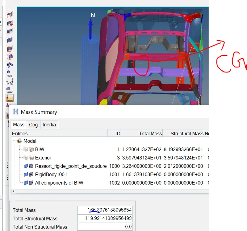
as per condition of the challenge the mass shown in the image is 166.30 kg and we need to add 534 kg to get it balance the 700 kg ,inorder to shift the at back of the driver seat for the better COG.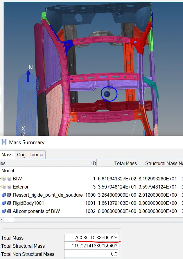
I have added mass in the occupant area and engine area and CG is at back of seat. The position of the CG tells during the crash the car about to roll ,pitch and yaw movements are vary so to avoid that the CG should maintain properly.
6)Initial velocity as shown in picture:
we have to give the boundary condition here we have to giving initial velocity with that the model move in the direction we provided velocity since the is created side of the car(y direction) so that the model move towards pole to get it crash,for the initial velocity the whole model of the nodel biw we have to consider. as shown below.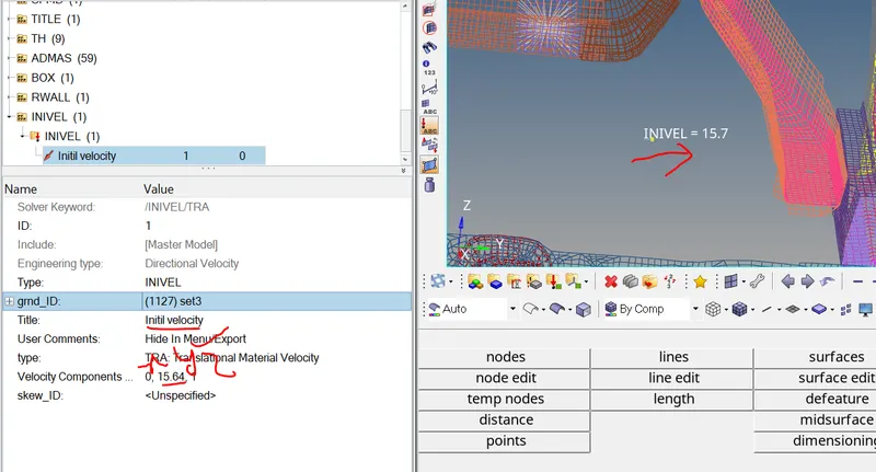
7)Time step 0.5 to 0.1 microseconds:
the minimum time step value we have chnage here the given value is in microseconds we need to convert to mille seconds to get it proper value after conversion the value becomes 0.0005 as Tmin value. (Model tab >cards >ENG_DT_NODA)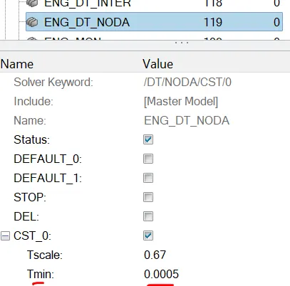
Sectional force in the cross member:
To create the sectional force we need section of elements and local frame on the cross memeber. The cross member is that supports the structural stiffness and alignment of the horizontal frame .If we consider the I-section the top and bottom flange horizontal members and middle is cross memeber. To create that first in solver tab ,right click >create >section,name is cross member and same right click in the solver tab,create >skew,moving>select the origin point where my local moving frame should be and select the point where it should be perpendicular to force direction which is Z-axis here and yz plane is created. Then goto section >select the entity that we created in that we have N1,N2,N3 are the forces and skew ID we have to give and two row of elements.as shown below.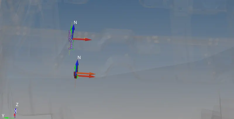
Fig:Two row of elements N1,N2,N3 shown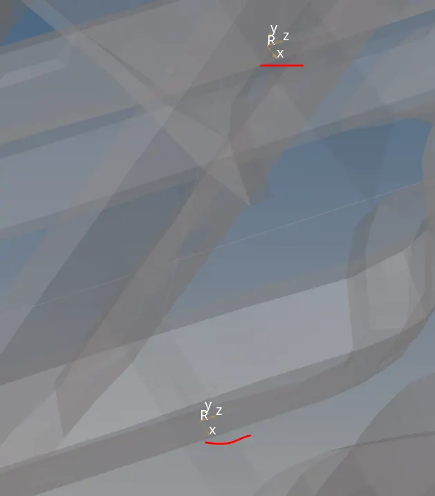
Fig: local moving skew
11)INtrusion at B-pillar ,Hinge pillar and fuel tank region. Provide recommendation on what can help to reduce fuel tank intrusion:
Intrusion is node or element that we select to with reference so that we can measure the diplacement from that point to reference how much it moved.since it mentioned in the challenge node at the B-pillar,node at the fuel tank and hinge pillar. Here the two nodes are connected by using spring 1D > springs >select the 2 node springe select the 1st node deformation side and 2nd node exactly opposite side of the node >create. we need to assign the mass and stiffness by creating property and in the card image select the spring and enter the mass and stiffness 0.001 and 0.1 .Assign this propety to the spring elements,in outblocks >cretate one out block and edits to be made as shown below.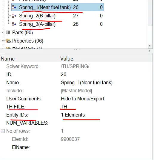
like the i follwed for the rest of two springs. Created shown below.
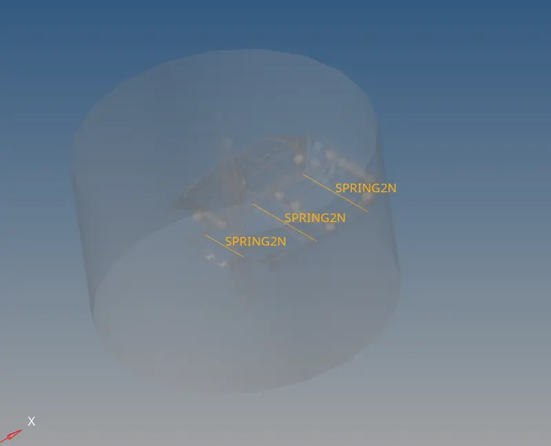
Fig: springs created in respective location as mentioned
Peak velocity of inner node of the door:
For this i considered the node 336892 ,to create the time history solver tab,right click>create >TH >node name it as peak velocity in the card at the entity id selct the node (336892).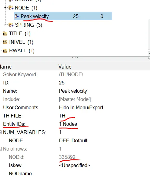
Post-processing results: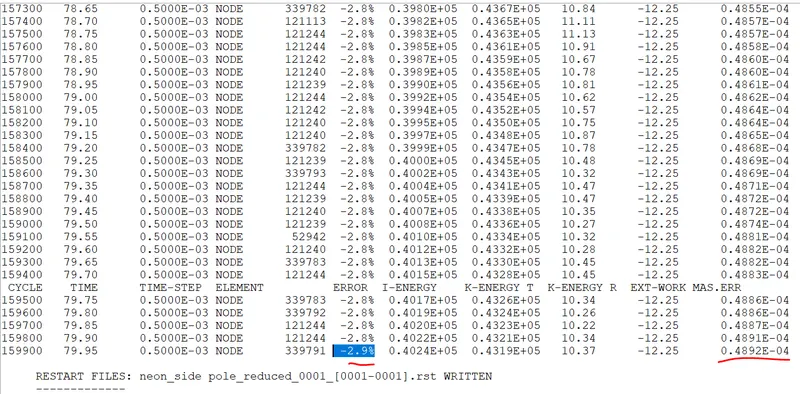
Mass error = -2.9%
Energy error = 0.4892E-04=0.00004892
Elapsed Time =4589.89 s
Total number of cycles =160001
The results within the control we proceed further.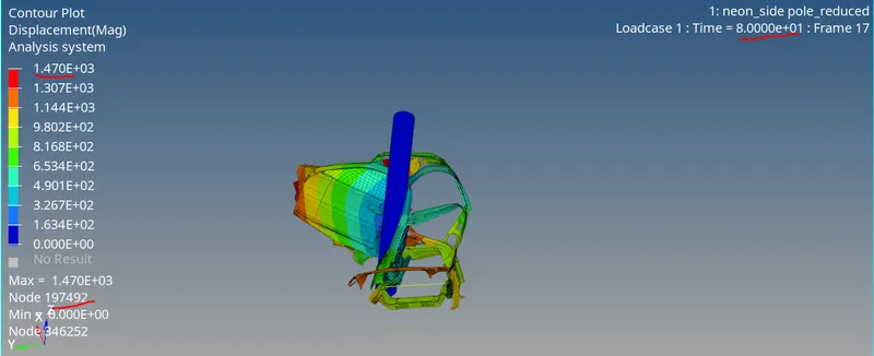
Fig:Displacement contour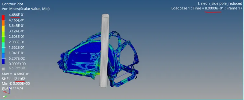
Fig: Vonmises contour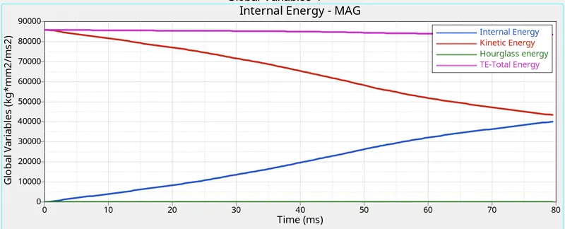
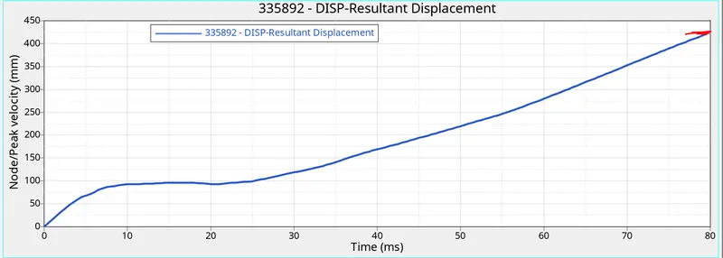
Observations: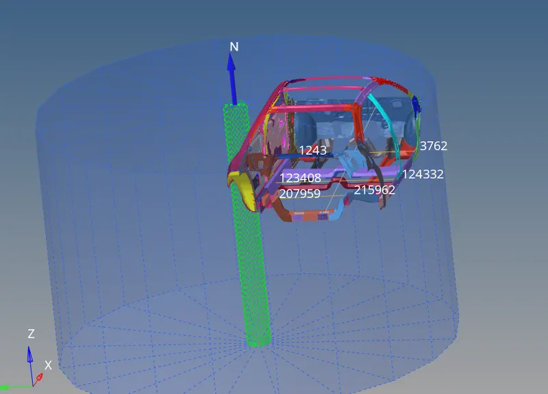
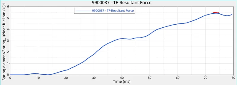
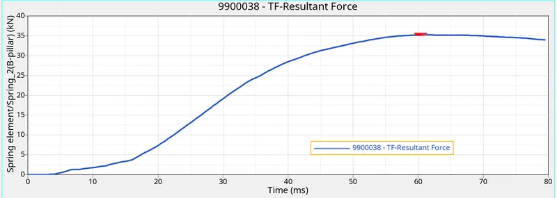
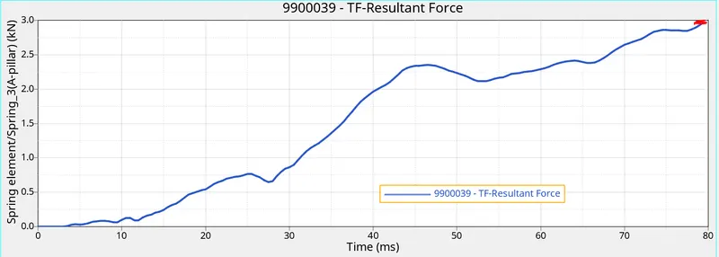
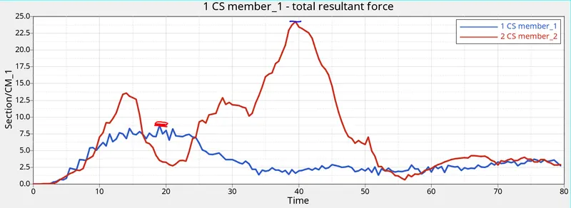
since the nodes not mentioned in the challenge but where nodes have to be mentioned based on that selected nodes shown above where near the fuel tank and ,B-pillar and A-pillar regions. the forces for the regions shown below at the time mille seconds(ms).
1. B-pillar resultant force = 79.5 ms -Xaxis.
= 35.2 KN (max) -Yaxis.
2. A-pillar resultant force = 79.5 ms -Xaxis.
= 3.103 KN - (max) -Yaxis.
3. Near fuel tank resultant force = 79.5 ms -Xaxis.
=5.43 KN -(max) -Yaxis.
4.Cross member_1 resultant force =79.5 ms -Xaxis.
=8.748 KN-Yaxis.
Cross member _2 resultant force =79.5 ms -Xaxis
=24.2 KN -Yaxis.
5.Peak velocity 335892
Resultant displacement =423.388mm
1 .from the above results above in the middle the more force is travelling through the intrusion node created and connected by the 2 node spring with less stiffnessa and mass the more the force more the displacement from the results.
2. The mass added to right side and CG point which is at the back of the driver seat and the trnasfer the force some what more to back towards the fuel tank region comare to A-pillar side.
3.If we see the energy plots the internal energy increase as the deformation increase the transfer of the energy between node to node also increase and it is nodal time method. The Inertial mass changes the velocity changes results in decrease the kinetic energy in the plot. and the Hourglass energy is zero because we have used the intergated QEPH element formulation to avoid that. That why hourglass energy is zero from the graph.
4. From the peak velocity node the displacement is increasing as shown in graph.
5. From the crossmember ,the crossmember2 which experience deformation first and which is close to the pole also and the deformation increase can see difference in the plots as well.
6.The graphs shown the more force more the deformation more the displacement . the Bpillar and fuel tank experience more displacement so counterbalance that if we reinforce that regions we can try to reduce like adding thickness or using composites.
Result:
The side pole crash test on BIW component of passenger vehicle has been performed using Hypermesh tool , Radioss solver and the Plots and contours shown.