Week 6
Aim: For the given Rear Door FE model implement the connections based on connections in front door model
Theory:
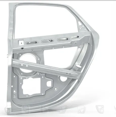
Fig: Skeleton view of rear door
The above image is rear door which is without skin in this we could see different connections like spot weld,rigid connections. The perforations (holes) which we see in the above image are the mounting areas to cover the skeleton.In this challenge i have used where two sheet metals are close to each other in that area i have used spot weld type connection mostly. And two sheet metals with hole area close to each other used RBE2 element many node is being used. In where spot weld connection to establish in that area i have used rigid connection as well to differentiate the connection because connection data is not provided.
Procedure:
Import the geometry from the local folder File ˃ input ˃ Nastran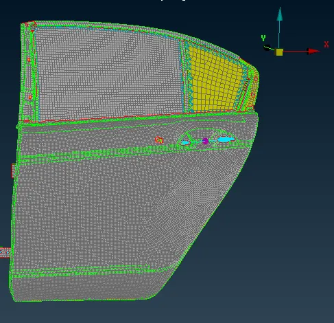
Fig: imported geometry
1.Hinge area:
once the model is imported its aligned to global coordinate axis i have developed a connection near holes area rigid connection used. Here we have to remember the when we open the door it should move front and back reference of the global coordinate axis its Z-axis,we have to release Z direction constrain consideration
Operation:
Goto ˃ nastran ˃ Elements ˃ RBE2 ˃in this we have two node and many node which is available select the many node. Goto node selection mode and i have selected loop option to all nodes in one shot and RBE2 many node window open as shown below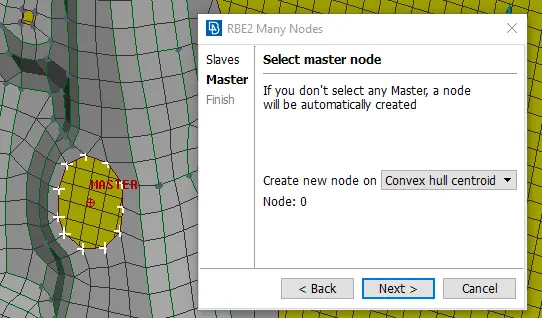
Here we follow 2node type can be used to establish rigid connection that is slave node and master node,in the image left side white colour nodes on the hole area is called slave nodes and middle red node is master node once defined this nodes goto finish window appear as shown below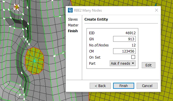
Here we need the door should move in global z axis we need to remove the degrees of freedom(dof) in z axis,in CM box we have to mention 12345 only then finish,the connection is established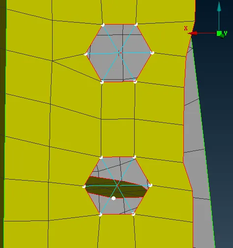
Fig: Rigid connection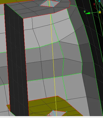
Fig: stem by two node RBE2
2.Overlap:
Here when the sheet metal is one over the other which is close is close to each other imagined a connection called spot weld.
Operation:
Goto ˃ topo ˃ points ˃on COG(select the edge from the element and middle click blue dot is created. Now we have to convert this cog point to 3D point so that this can be seen as hexa shape ,the hexa element act as slave node and surrounded nodes act as master node(goto ˃ assembly ˃ convert ˃3dpoint,select the point and middle click ˃connection type window appear select the spot weld connection option and ˃ok
ii)goto˃ assembly˃connection manager˃ selection assistant window appear,select the point and middle click˃the connection manager window appear.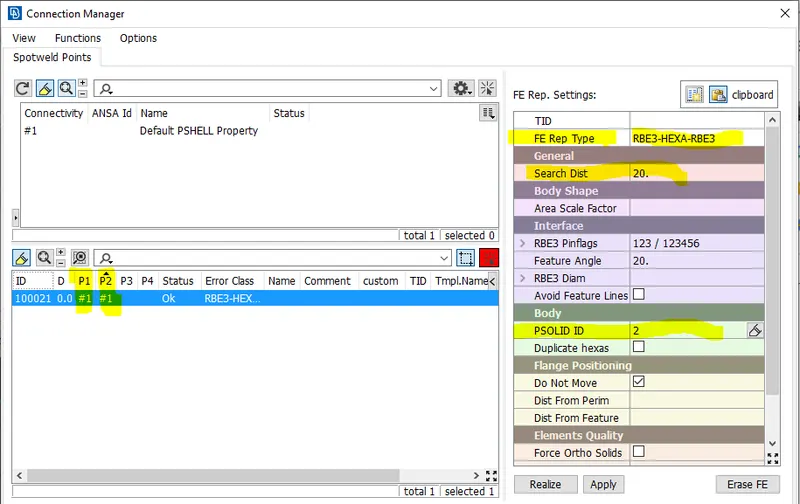
We have to manually enter the highlighted one
FE Rep Type:RBE3-HEXA-RBE3
Search Dist: 20
Body
PSOLID ID:shift+?(used this option create solid id)
Define P1 and P2
Apply
Realize
Once the connection is realize the status shows ok and connection rep is RBE3-HEXA -RBE3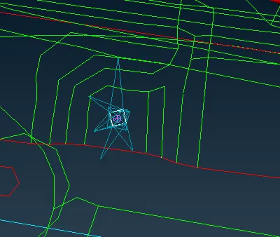
Fig: spot weld Representation
*when 3 holes can be seen to join i have used cluster RBE2 used and with help of the cluster node and other side node created stem connection as shown below 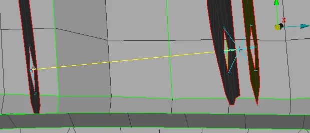
Fig:Cluster node and 2 node RBE2 connection
3.Concentrated Mass(Con MASS):
In this rear door connection the concentrated mass elements are Door Handle,Rear view mirror,Glass motor
operation:
Goto ˃nastran˃RBE2,many node˃select the 1st hole and and 2nd hole and its shows stem connection with red node in the middle(which is center point)
We have to apply con mass element connection at that node
Goto˃ nastran˃CONMI,ConMM2,nodes˃select the middle node in the connection˃conm page opens give the value of M=1e-4(1 ton equal to 1000000),100/1000000
Here 100gms is my door handle weight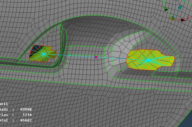
Fig:Concentrated Mass Element Connection
Once its established it looks as thick dot as shown in image
4.Cbush Element:
In Order to create the Cbush element we need to create FE around the perimeter of the glass to do that
operation:
Goto ˃mesh˃perimeter˃FE2 Curve ˃select the all edge of the glass and middle click the FE line created in blue colour. This FE line in ANSA called as spotline.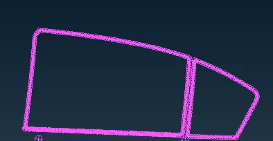
Here convert the FE lines individually once converted to spot lines it looks as shown above.
In connection manger select the FE line enter the values as shown below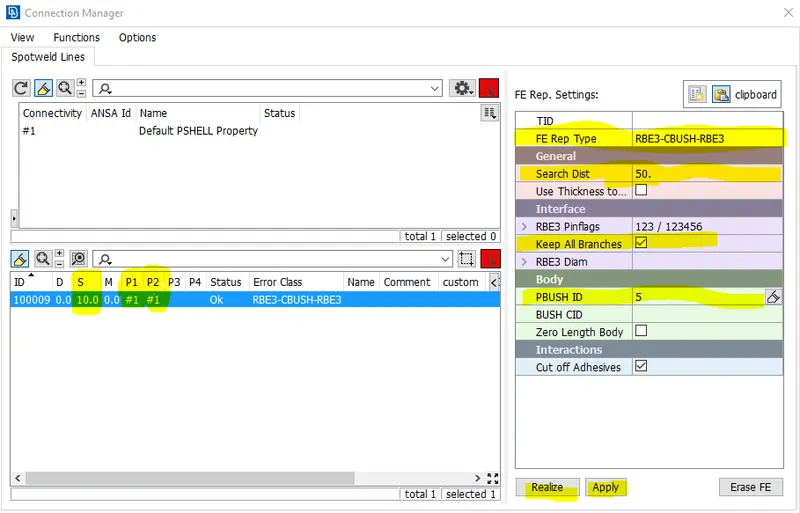
Likewise i have applied all sides. Here the thumb rule is the window is closed and apply the cbush element connection.once the connection is established in all sides its looks as shown below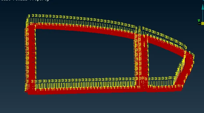
Fig: CBUSH Element Connetion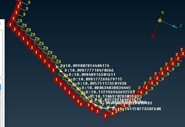
Fig:CBUSH Element connection with spacing of 10(S=10)
Here the orientation of the CBUSH elements are the coordinate orientation and the ID is 0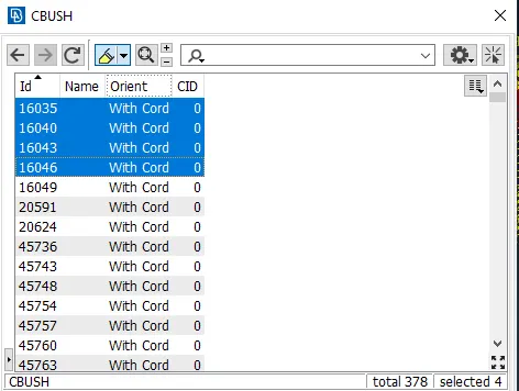
Here orientation is coordinate based and ID which is zero means the local coordinate of the CBUSH aligned to Global Coordinate system which we see in GUI.
Learning Outcomes:
1. I have learnt how the physical connection like bolt,spot weld,conmass,can be represented in ANSA
2.And also Learnt different type of connection type like which is two node RBE2 connection and many node RBE2 and cluster RBE2 and stem connection.3.And also types of the representation that we give for different connection
4.Understood methods of selection of nodes and elements to nodes
Result:
For the given Rear Door FE model the connections have been implemented based on connections in front door model
Here bellow i have attached FE Rear Door model and implemented connection:
https://drive.google.com/file/d/1I2UK-lZC_bFRKBzKwqYTfxaoorGsZixE/view?usp=sharing