Week 12:Project 2-Meshing of Rear Wheel Holder challenge
Rear Wheel Holder Geometry Extract Mid Surface Apply 2D meshing using Hypermesh Optistuct Solver
Aim: For the given Rear wheel holder we need to perform the mid surface and 2d quad meshing with the mentioned quality criteria and assign material and property to the component.
Quality Criteria:
Target length = 5
Aspect Ratio = 5
Warping = 15
Skewness = 45
Taper = 0.5
Minimum length = 2
Maximum length = 8
Minimum Quad angle = 45
Maximum Quad angle = 135
Minimum Tria angle = 20
Maximum Tria angle = 120
Jacobian =0.7
Theory:
Here the given component is sheet metal component which is uniform thickness if we say the sheet metal component which is uniform thickness. Metal components are also have the varying thickness like cast iron ,aluminum. If the component or the part uniform thickness assume to be BIW component. Here I have followed the auto mid surface extraction because of the uniform thickness which save the lot of the time instead of the going manual mid surface. After the extraction I found some features not captured and I did it manually by offset method. Here I found similarity and used reflect option.
Procedure:
1.Import the Cad geometry
2. Extra Mid surface( Auto mid surface)
3.Quality Criteria
4. Meshing and mesh editing tools
1. Import the CAD geometry:
Import the cad file from the internal folder by File >Import >model and select the rear wheel folder file and import or File >open >model also we can open . once imported we can click in GUI and press F it will fit in the screen.
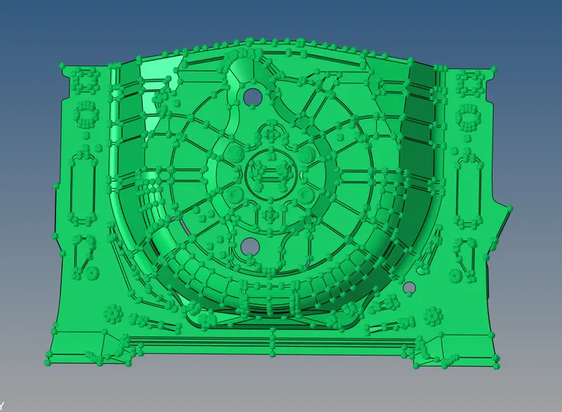
Fig: Imported the CAD geometry
2. Extract the mid surface:
Here I have followed the auto mid surface extraction because of the uniform thickness which save the lot of the time instead of the going manual mid surface. After the extraction I found some features not captured and I did it manually by offset method. Geometry >Mid surface and in extract options select the Offset and select the component and then Extract. After the extraction hide the parent geometry and check manually any surfaces are failed to captures here I found some surfaces are failed to capture and I did it manually and fixed the issue. And here I found similarity from the geometry and Geometry >surface edit >Trim with lines option and select the surface to trim select the coordinate and trim here suppose we want to make the trim in vertical select the points in normal to the we have to select point . before that here I have measured the distance and created the mid point which is my base point based on this it will make trim. And I did one side the mesh and duplicate the mesh elements and reflected which will save my time .2D > automesh >select the surface and change the target length is 5 and then ok. Preference > select the criteria file setting > and entered the given quality criteria >apply > Ok. Then opened the Automesh panel and done the surface by surface meshing and features need to capture must and should here. And small features I removed due to failing min length it will fail my elements as mentioned in the article. Once I completed the meshing Tools > Reflect >Select the elements and right click on elements and duplicate the elements and select the base point which we created earlier and fix to axis which is in similar and reflect . I used the Delete > elements by face I deleted the elements which are not connected and not taking the shape of the geometry and did manual meshing . Tools > Edges and select the component and >find edges it will show the free edges which is not connected with adjacent element , here I found some of that elements and replaced (Paste)that node with adjacent node so that it form the connectivity. Here I have used the multiple options to bettering the mesh flow that’s are optimize the element ,replace the node, drag tria, split edge, combine trias, remesh option as well. In the model tree I created the material to my component which is MAT1 material and created property to the particular thickness component which is 0.75 and the same property assign to component . images of the component mentioned below.
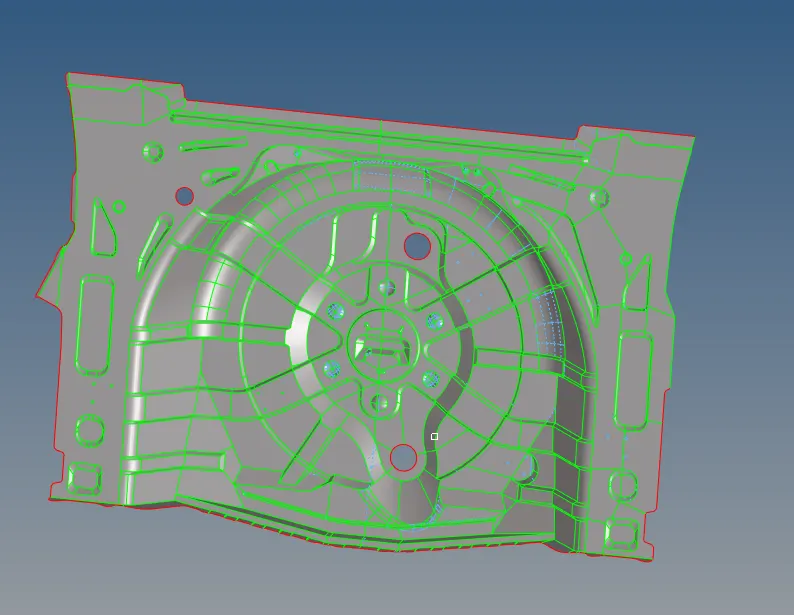
Fig: Extracted Mid surface form the parent Geometry
3. Quality Criteria:
prefernces >Criteria file setting >enter the given criteria values as shown below
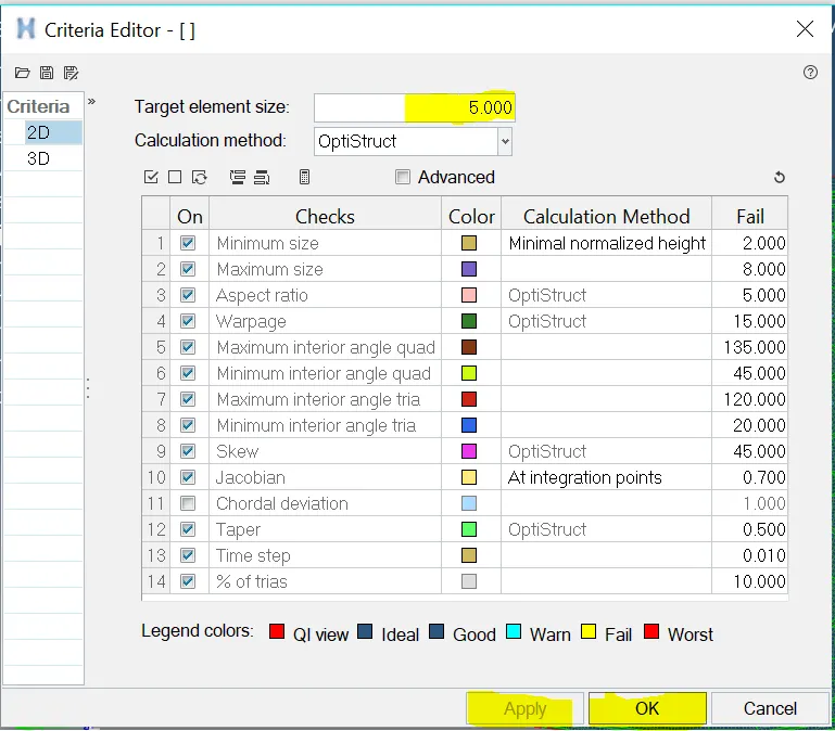
Fig: Quality criteria for the rear wheel holder
4. Meshing and mesh editing Tools:
2D > Automesh >selectht the surface and apply meshing and below mentioned meshed component and satisfied the quality criteria.
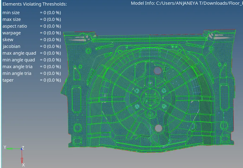
Fig:Meshed component and satisfied the quality criteria
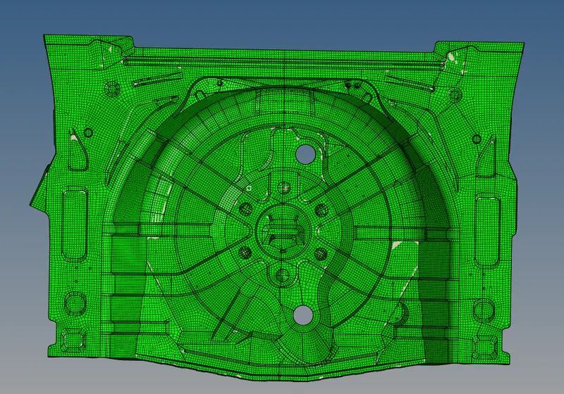
Fig: Material assigned to component
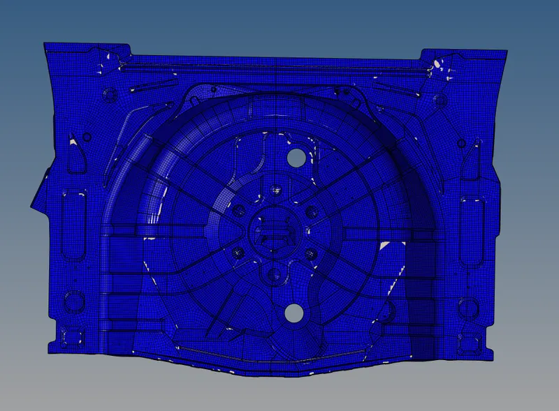
Fig: Property and thickness assigned to component
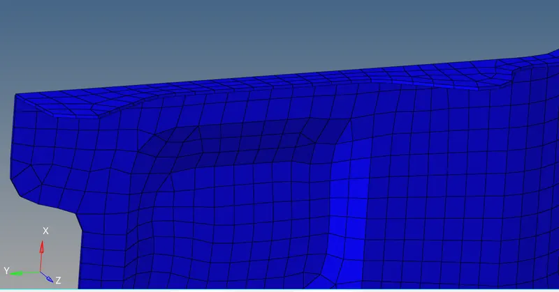
Fig: Represented as 2D detailed view
To check any free edgesin the middle i used Tools >edges >select the componet and find edges as shown below.
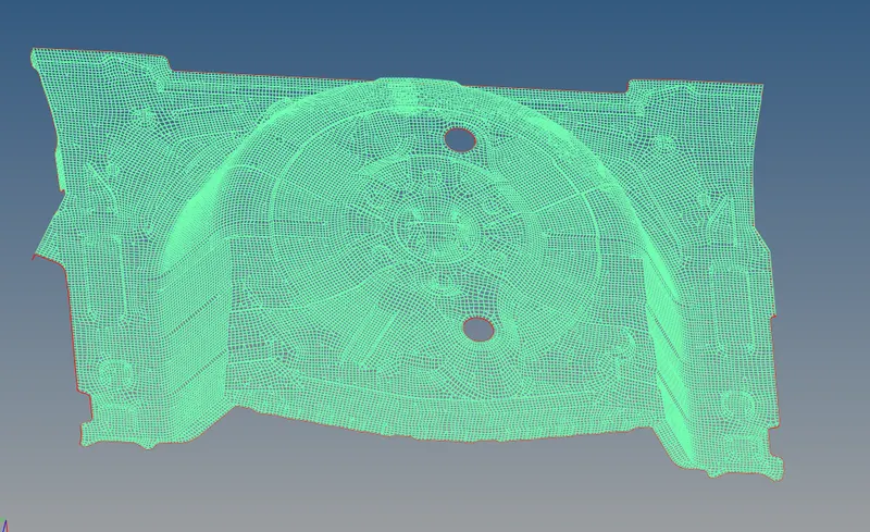
Fig: No free edges in middle
Out comes of the challenge:
1. I learnt the modelling
2. Understood the geometry issues
3. learnt the where to apply auto mid and manual mid surafce
Result:
For the given Rear wheel holder mid surface and 2d quad meshing with the mentioned quality criteria and assign material and property to the component has been done.