Week - 4 - Crash Box Simulation
Aim : For the given crush tube FE model we need to simulate the model aganist the rigid wall with different thickness and we need to get the outputs for the given requests.
Requests:
Input .k file and output files (d3plot, glstat, sleout, rcforc)
- Animation of the final simulation
- Cross-sectional force generated in the middle of the crashbox (along its length)
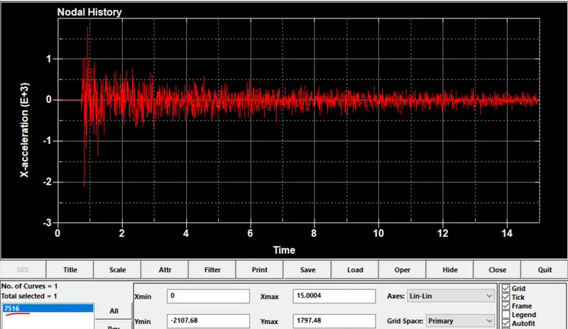
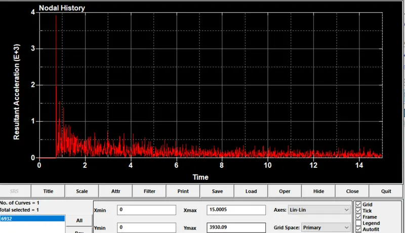
- Acceleration plot of a node in the middle of the crashbox (along its length)
- Maximum directional stress and strain along the length of the crashbox (X strain, Y strain etc)
- Plot of all energies (total, internal, kinetic, hourglass, sliding)
- Compare the accelerations and stress/strain plots of 1.2/1.5mm crashboxes.
Procedure:
1.for the given .k file consist of elements and node information.we need to create the create the rigid wall normal to the crush tube and assign materail to the model, here we will assign the material is MAT_024 linear plastisity material as it mentioned that simulation starts from the elstic state to plastic region for the linear plastisity material card is suitable for that.
2.we have consider the mild steel material material and here the GM MM MS unit system is follwed for that following following values are shown below.
Row=7.85g/cm^3 is
=7.85/(1000)3 =7.85E-9.
E =210Gpa
=210E9 kg/ms^2
=210000000/1000000000
=21/100=0.21 g/mm ms^2
N=0.3
SIGY=250Mpa
=250E6 kg/ms^2
=25/100000
=2.5E-4 g/mm ms^2
3.once the material is card is deined we need to create the boundary condition to the model in this challenge the boundary condition is Intial velocity is 50kmph and convert to the mm/ms then it will be the 13.889 mm/ms.
1. to create the rigid wall,using model and part >create the entity >select the rigid wall ,cre,planar select tail node and head node and create >apply done as shown below.
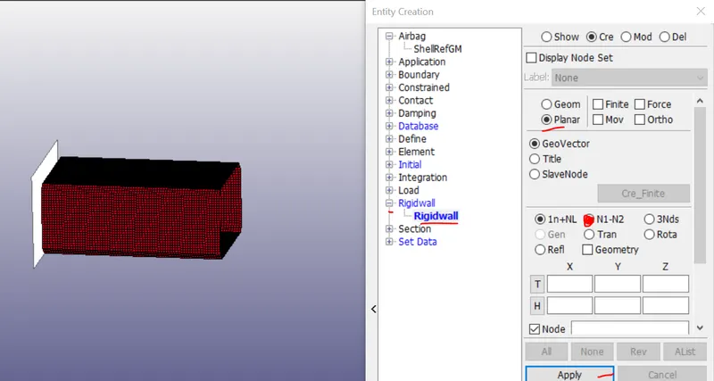
Fig:Rigid wall created.
To assign a material ,Model and part >keyword manager >all,MAT and MAT_024 piecewise_linear_plastisity as shown below.
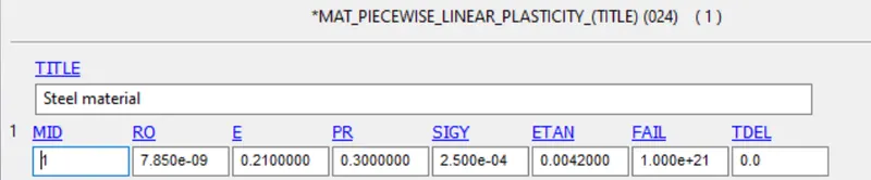
Fig:Material card created.
Boundary condition applied to the model,model and part >create entity >intial ,velocity,cre,velocity is to apply in the direction of the negative X direction then only the model crsh aganist the wall, if we give it in positive X direction then the model move away from the wall which we dont want.,as shown below.
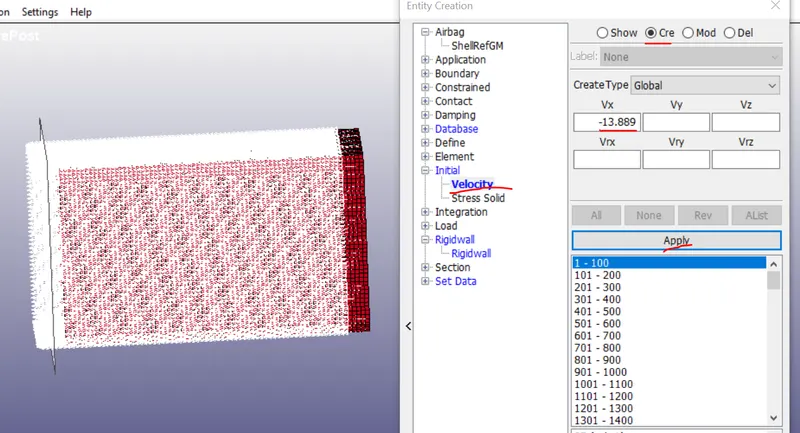
Fig:Boundary condition applied
Here shell element section we have used ,to do that model and the part >keyword manager >all,section,shell and select the ELFORM is 2 and the Thickness is 1.2mm >accept and done.
we need to create the output deliveriables from the simulation ,cross sectional force needs to create the in the middle of the crush tube to do that from the model and part >create entity>database>cross section i have section using plane in the middle of the tube using N1,N2 options. as shown below.
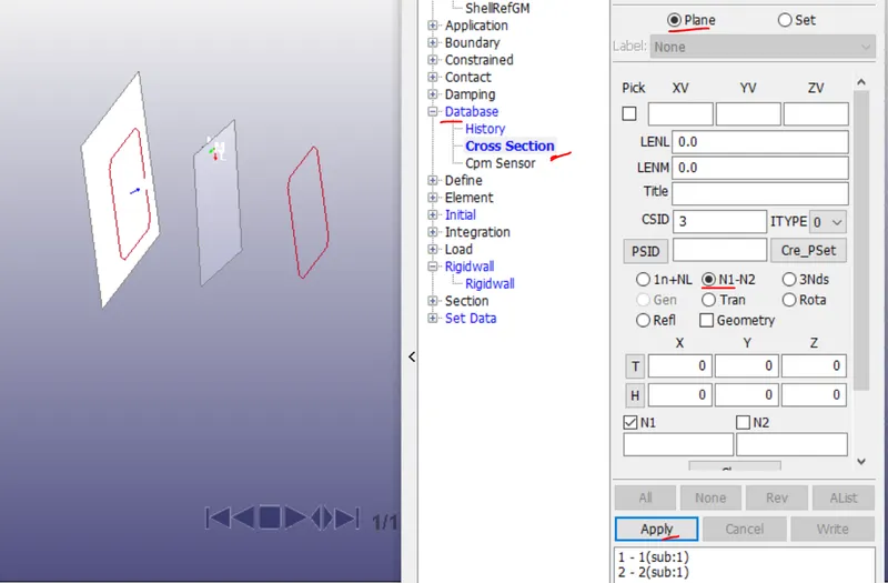
Fig: section-plane created
Follow the same method in datebase >Time history ,nodes by edge gives flexibility to select the nodes easily at the section of the the plane.
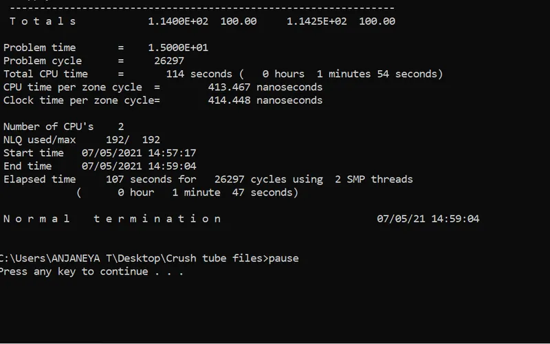
Finally for the output files that we is database > binaryD3plot, and database >ASCII files >glsat,MATSUM,eleout,SECFORC. And we have to mention the termination time as well i ahve used the 15ms and 0.01ms time used for the start the simulation.
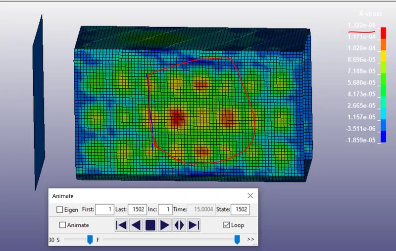
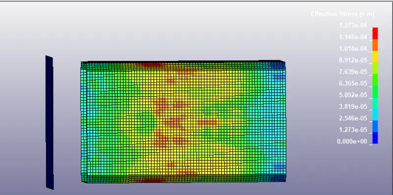
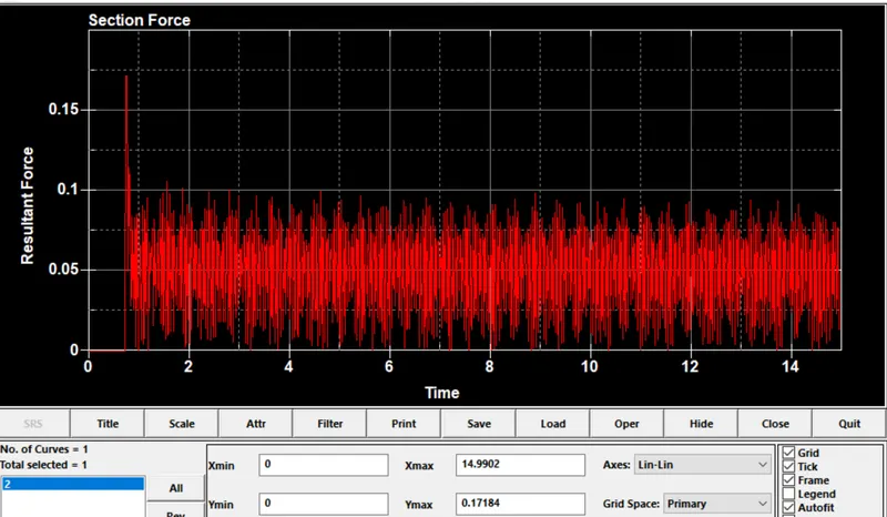
Post -processing :when the Thickness is 1.2mm is used
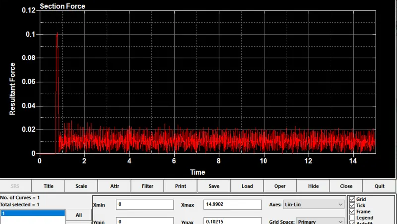
Postprocessing : Thickness of 1.5mm
Observation:
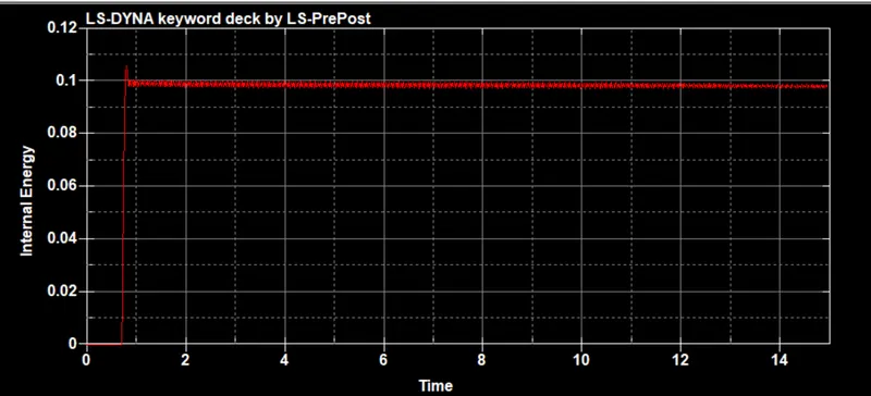
i)we can observe that we have used the ELFORM _2 because of that we have avoided that the hourglass energy as shown zero from the plot for both 1.2 and 1.5mm thickness.
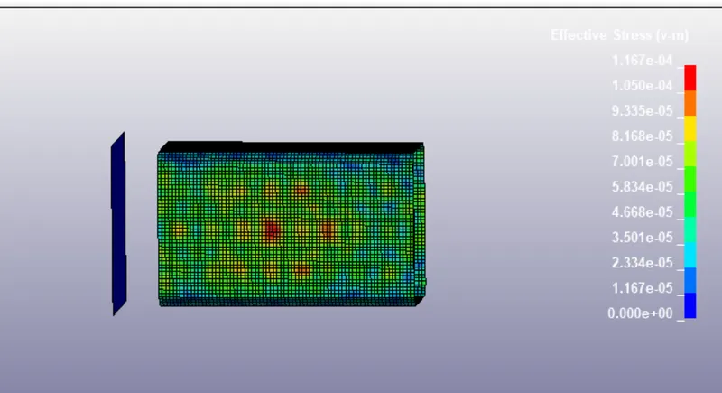
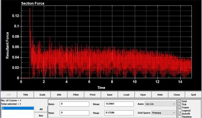
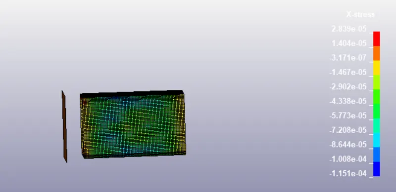
ii)From the vonmises stress graph as the thickness increase the more force require to deform the body and the for the thickness 1.5mm the stress generated. from the sectional force plot in the 1.2mm thickness the we get the max peak at the 0.13586N and for the thickness of the 0.10215N if we consider the 1.2mm thickness tube when it hit the rigid wall the propagation of the deformation curve goes some extent smooth we get max value and the for the thickness of 1.5mm the deformation of the curve propagation is slow.
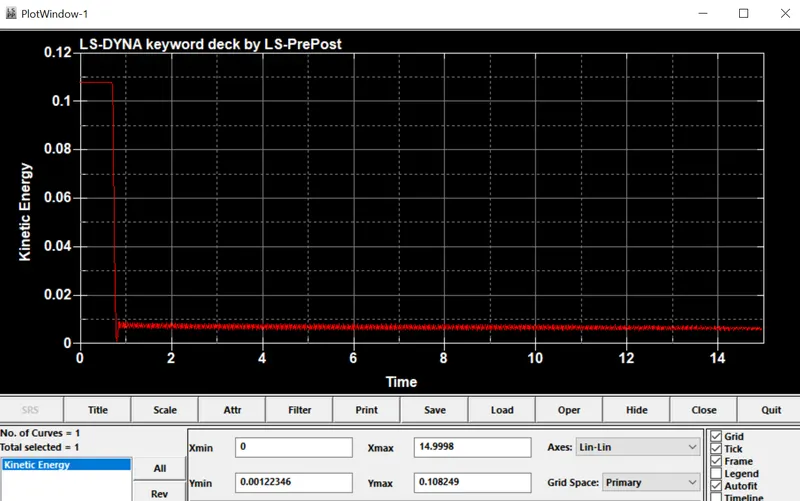
iii)when the tube hit the rigid wall it undergo contineous deformation because of that the internal energy transfering contineously it shows in increasing ,the more splike we can observe the complte tube come and contact with rigid wall. at the same time kinetic energy decrease the velocity decrease the moment when tube hit the wall and after the few seconds the velocity will not be the sam it decrease the mass remains the same the velocity decrease , the decreased velocity multiply with mass values becomes less that what we can observe in the graph.
Result:
For the given crush tube FE model simulated aganist the rigid wall with different thickness and post-processing results are shown
Procedure:
1.for the given .k file consist of elements and node information.we need to create the create the rigid wall normal to the crush tube and assign materail to the model, here we will assign the material is MAT_024 linear plastisity material as it mentioned that simulation starts from the elstic state to plastic region for the linear plastisity material card is suitable for that.
2.we have consider the mild steel material material and here the GM MM MS unit system is follwed for that following following values are shown below.
Row=7.85g/cm^3 is
=7.85/(1000)3 =7.85E-9.
E =210Gpa
=210E9 kg/ms^2
=210000000/1000000000
=21/100=0.21 g/mm ms^2
N=0.3
SIGY=250Mpa
=250E6 kg/ms^2
=25/100000
=2.5E-4 g/mm ms^2
3.once the material is card is deined we need to create the boundary condition to the model in this challenge the boundary condition is Intial velocity is 50kmph and convert to the mm/ms then it will be the 13.889 mm/ms.
1. to create the rigid wall,using model and part >create the entity >select the rigid wall ,cre,planar select tail node and head node and create >apply done as shown below.
Fig:Rigid wall created.
To assign a material ,Model and part >keyword manager >all,MAT and MAT_024 piecewise_linear_plastisity as shown below.
Fig:Material card created.
Boundary condition applied to the model,model and part >create entity >intial ,velocity,cre,velocity is to apply in the direction of the negative X direction then only the model crsh aganist the wall, if we give it in positive X direction then the model move away from the wall which we dont want.,as shown below.
Fig:Boundary condition applied
Here shell element section we have used ,to do that model and the part >keyword manager >all,section,shell and select the ELFORM is 2 and the Thickness is 1.2mm >accept and done.
we need to create the output deliveriables from the simulation ,cross sectional force needs to create the in the middle of the crush tube to do that from the model and part >create entity>database>cross section i have section using plane in the middle of the tube using N1,N2 options. as shown below.
Fig: section-plane created
Follow the same method in datebase >Time history ,nodes by edge gives flexibility to select the nodes easily at the section of the the plane.
Finally for the output files that we is database > binaryD3plot, and database >ASCII files >glsat,MATSUM,eleout,SECFORC. And we have to mention the termination time as well i ahve used the 15ms and 0.01ms time used for the start the simulation.
Post -processing :when the Thickness is 1.2mm is used
Postprocessing : Thickness of 1.5mm
Observation:
i)we can observe that we have used the ELFORM _2 because of that we have avoided that the hourglass energy as shown zero from the plot for both 1.2 and 1.5mm thickness.
ii)From the vonmises stress graph as the thickness increase the more force require to deform the body and the for the thickness 1.5mm the stress generated. from the sectional force plot in the 1.2mm thickness the we get the max peak at the 0.13586N and for the thickness of the 0.10215N if we consider the 1.2mm thickness tube when it hit the rigid wall the propagation of the deformation curve goes some extent smooth we get max value and the for the thickness of 1.5mm the deformation of the curve propagation is slow.
iii)when the tube hit the rigid wall it undergo contineous deformation because of that the internal energy transfering contineously it shows in increasing ,the more splike we can observe the complte tube come and contact with rigid wall. at the same time kinetic energy decrease the velocity decrease the moment when tube hit the wall and after the few seconds the velocity will not be the sam it decrease the mass remains the same the velocity decrease , the decreased velocity multiply with mass values becomes less that what we can observe in the graph.
Result:
For the given crush tube FE model simulated aganist the rigid wall with different thickness and post-processing results are shown