Assignment 2-RADIOSS Engine File Editing & 3D Meshing Challenge
For the given problem we need to find the speed of the sound (C)=?
From the theory the speed of the sound is (C)= √E/ ρ,
Here the given material is steel material and the values of the E=205GPA,can also be written as 205000MPA
And Length(l) =1000mm
And Density(ρ)=7.8 x e^-6 kg/mm^3.
Δt =l/c=l/√E/ ρ
1pascal =1N/m^2 or kg/m.s^2
C=205000 x(1000)/(1000)x(1000)^2
(ρ)=7.8 x e^-6 kg/mm^3
(ρ) = 7.8 xe^-6 xe^3
=7.8 xe^-3
(ρ) =0.0078 g/mm^3
(C)= √E/ ρ,
=√(205000/0.0078) ms^2/mm^2
(C) = 5126.6023 ms^2/mm^2
Δt = 1000/5126.6023
Δt =0.1951 mm /ms^2
Here i have follwed the Gram (g), mille meter (mm), mille sec (ms).
Here we are converting from kg to grams higher to lower so we have to multiply with 1000
Aim: For the given component we need to perform the 3d mesing and satisfy the given TET collapse value .
Quality Criteria:
Mesh size is 5mm and Tet collapse =0.15
Procedure:
1. Import the Cad geometry
2.Apply volume mesh
3.Satisfy the TET collapse value.
Theory:
Here the given geometry has two two components one is casing and another is HUB. As per the thumb rule is if the thickness is more than 5mm we have to perform the 3d meshing or solid meshing. Here we can do it by 2 ways with the given elment size we can do surface meshing and from the 3d panel we can apply tetra mesh by selecting the component. and 2nd one directly we can go to 3d panel we can directly generate the volume. Here i have used the 2nd one which 3d > Volume terta >chnanged the element length and tet collapse value.
1. Import the cad geometry:
Import the cad geometry from the local folder and File >import >Geometry> select the respective file and click import here the given file is STEP file so before import we have to change or we can also use File >open >model from this way also we can open the model. Press F we can fit the model In GUI we can change the geometry mode to TOPO we can see as shown below.
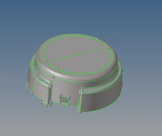
Fig: Imported Cad in TOPO mode
2.Apply Volume mesh :
Before going to volume mesh we have to set the current component. from 3d >volume tetra >select the component and changed the element length. Here i have used the Curvature and proximity option to capture the fillet regions properly and result of that i got the denser mesh at the fillet regions and the hole regions .
In the Tetra mesh parameters we have to change the parameters like instead of none i used the min tetra size value is 0.2 and in the same page change the value to 0.15 and Fill the voids and smoothing and Fix nodes.
Once volume mesh is generated turn of the geoemtry and use F10 chech elements and in 3d panel select Tet collapse value which is 0.15. Here i have found the some TET failure elements and using Tetra remesh option we can clear the failure element .
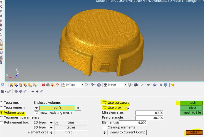
Fig: Options selected to Generate volume mesh

Fig: Volume Generated For the Casing component
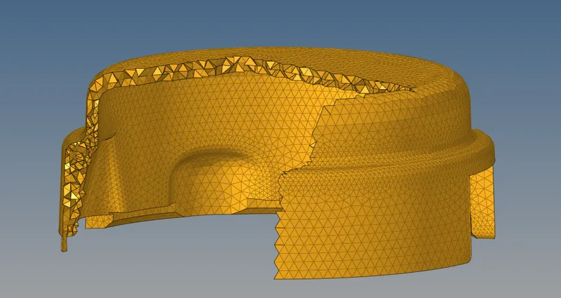
Fig: Cut section of the casing component.
Here the above are only for one component which casing and for the hub componet images as shown below.
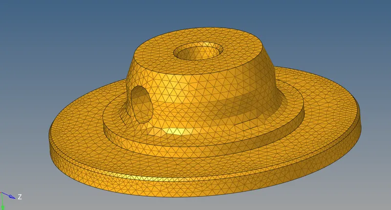
Fig : Volume generated in Hub component.
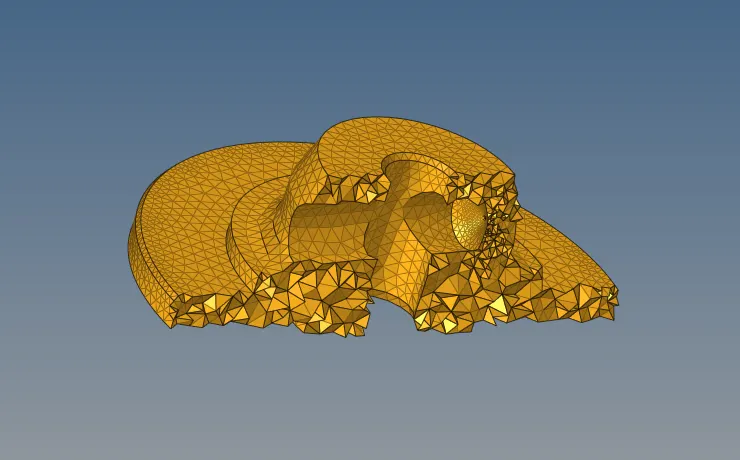
Fig : Cut section of the Hub
Out comes of the challenge:
1.Learnt the Solid meshing
2. Learnt the features capturing using options called curvature and prximity
3.satisfy the Tet collapse.
Result:For the given component the 3d mesing and satisfy the given TET collapse value has been done properly.
Aim: For the given componet we need to perform the3d mesh (hexa element)
Theory:
Here the given geometry has 4 components base component,arm curve, arm straight, hub component. Here we have to set the individual component as component and perform meshing. Here 4 components using 4 different option we can get 3d hexa mesh. 1st is using element offset,for the 2nd spin option,for the 3rd component linear solid, for the 4th component solid mapping. for the element offset we require 2d surface using quad element insted of mixed.
procedure:
1. Import the geometry
2.Apply 3d(hexa mesing) for the individual components.
1.import the geometry:
Import the cad geometry from the local folder and File >import >Geometry> select the respective file and click import here the given file is STEP file so before import we have to change or we can also use File >open >model from this way also we can open the model. Press F we can fit the model In GUI we can see as shown below.
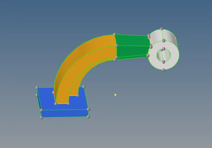
Fig : Imported Cad geometry
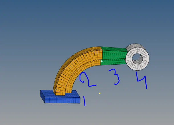
Fig: Numbered the geometry based on followed below.
1. Base component:
here select the individual component make it as current,for the base component. here base component make it as current perform the 2d meshing using quad element ,2d >automesh >change element length to 10 and select the surface change the element to quad. once it is done below options we have to select.
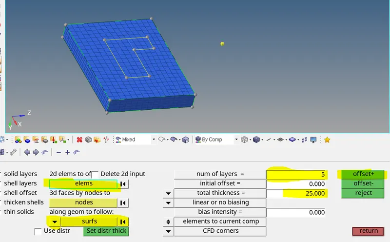
Fig: Selected options to follow for the base component.
2. arm curve:
from the 3d >spin >select the spin element option and as shown below. here we need Base point to spin the elements along the curve. F4 option using three point option select the curve and point select on the curve and create the center point.
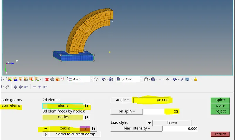
Fig: Selected option to follow for the arm straight
3.Arm straight:
Here 3d >liner solid . in this method we require the source elements and target elements using this two we can create solid in between for this to happen we need to face of the source element and same number of the elements we have to generate on the target surface using the 2d >automesh option.
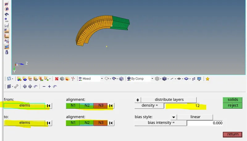
Fig: Selected options to follow for the arm straight.
Here the from elements means source elements and To elements means target elements
4. Hub Component:
here we will use the solid mapping 3d >solid mapping, it requires the 2d elements and node path and the target surafce. as shown below.
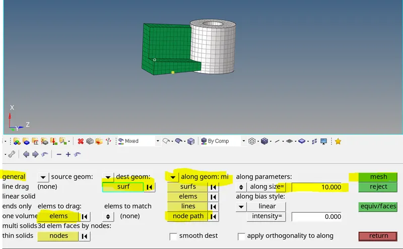
Fig : Selected options to follow for the Hub component.
Once the 3d meshing has been done for all components in the geometry we have to delete the 2d elements in the geometry using delete >by config > select quad 4 or quad 8 option> select the entity and delete.
Out comes of the challenge:
1.Learnt the Using options to get 3D meshing(hexa element)
2. Importance of the procedure to follow.
3. Learnt 3d meshing using Hexa element
Result:
For the given componet 3d meshing (hexa element) has been performed.