Week-6 Calculate the Stretch Ratio by comparing the ELFORM (-2,-1,1,2) with Ogden_Material Model.
Aim:For given hyperelastic material we need to take solid cube geometry and simulate the model at the various ELFORM( 1, 2,-1,-2).And need to find which ELFORM brings the simulated true stress and true strain plots match with the engineering stress and lamda graph.
Procedure:
1.import the given .k file(having material keyword)
2.create the geometry with given dimension.
3.we need to create the section(solid section).
4.Apply boundary condition(SPC & pescribed motion).
5.Assign the material and sction to the solid geometry.
1.import the .k file :
Here the given file has only material card. which is hyperelastic material.
2.create the geometry with given dimension:
In the challenge x=10,y=10,z=10 so we have to create solid geometry by using, elements and mesh > shape mesher > instead of the default value we need to keep 10 as shwon below.
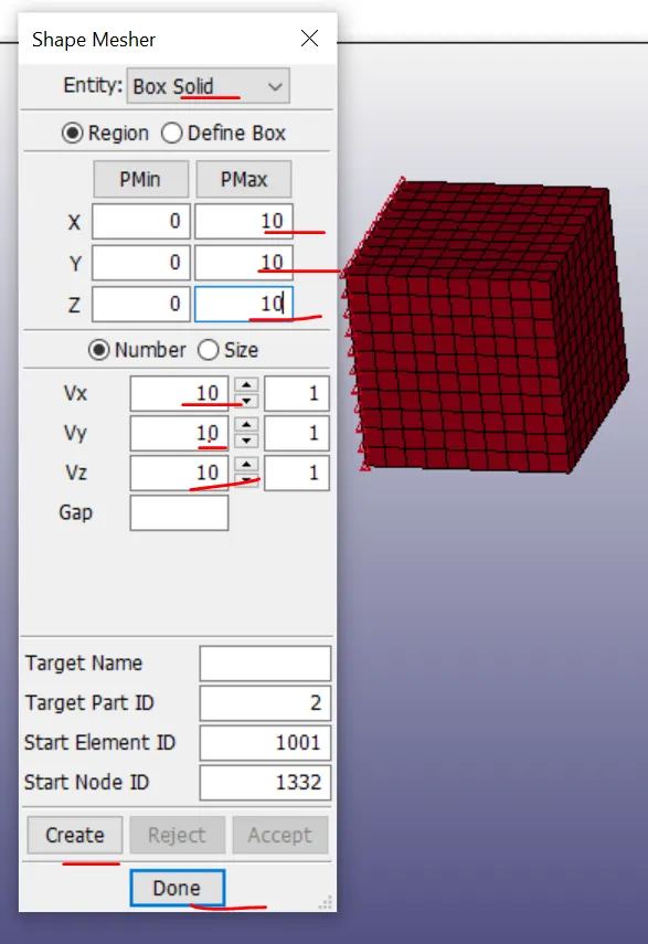
Fig: Geometry created
3.we need to create the section(solid section).
we have to create the the section for the solid model and mention the ELFORM as the 1 . after section is created we need to assign the material and the section to the part.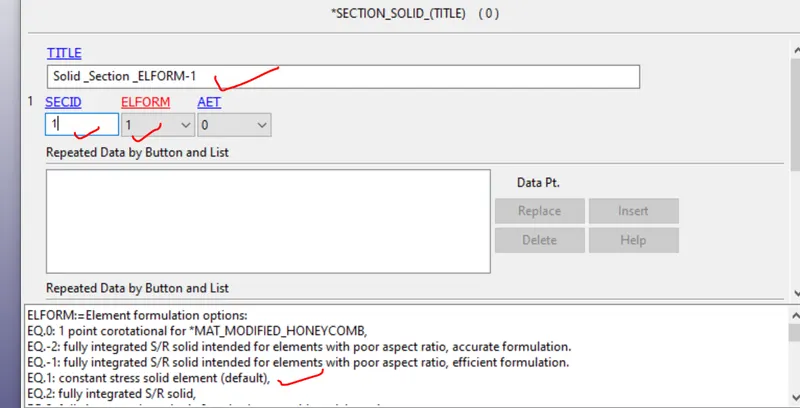
4.Apply boundary condition(SPC & pescribed motion).
we need to create the boundary condition to the model. i have used the spc and pescribed displacement.one side is SPC and opposite to that pescribed displacement. for the displacement i created the node set and in the pescribed displacement card set i assigned to that as shown below.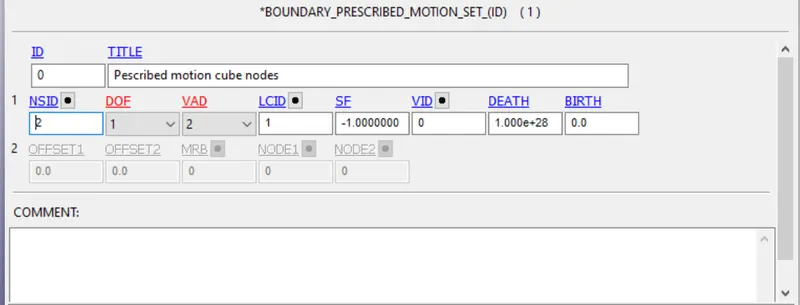
Here prescribed motion set card we need to free in X translation and to activate the displacement the number is 2 and and scale fator is -1.0 because if the displacement direction is negative . In the LCID the curve need to plot between ,
from the theory Lamda=1+engineering strain, lamda given value is =5 which is stretch value.
Engineering strain =lamda-1
=5-1
Engineering strain =4
Engineering strain =del/Lo (where Lo= 10 ,the length of the cube)
Del L =4*10
40
we need get the displacement of the 40mm,0,0 and the 40,40 we have to give in the LCID curve.
we are running the implicit analysis,to run the implicit follwing need to assign.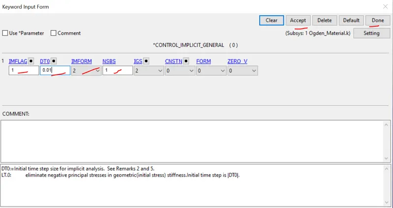
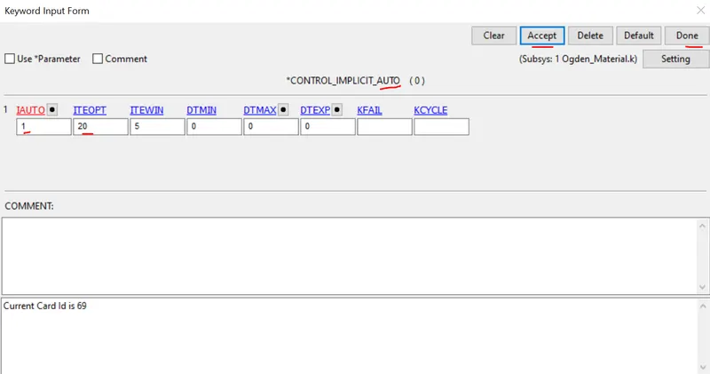
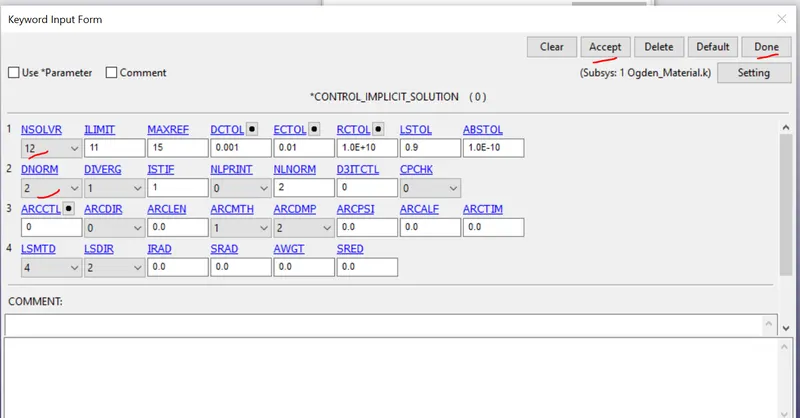
the recommended changes needs to be done.
Post -processing:
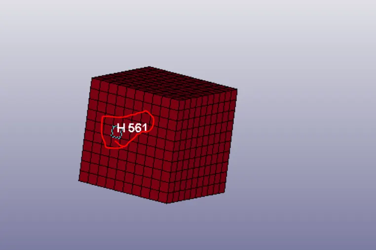
For the shown element is considered for all ELFORMS and DT =1 minimum is considered to write the files. and termination time is 5. within this 5ms the stretch should done.
Below i have mentioned the true stress and true strain graphs for all the ELFORMS and to get the strain on the element as mentioned in the challenge Database_Extend _binary key word we need to active the STRFLG is 1 then it will write all data.
Process to check the elemental strain :
1.open the D3plot and in the history select the element >then select one element from the one side of the cube as shown above image.if we select the element and plot it takes data from the 0 to 5ms . And save the data using save option
2. In the XY plot we can select the name that we save using in the History.on x axis we select the strain and y axis we select the stress.and plot.
3. using stress with respect to time and strain with respect time using this stress and strain we have to compare graph with the engineering which is given.
4. In this challenge we are using uni axial force so we have to compare with uniaxial engineering stress vs lamda graph. Here nominal stress is the engineering stress.
we have the formulas sigma t =sigma e (1+ engineering strain)
epslon t =ln(1+engineering strain)
=ln Lamda (where lamda =1+engineering strain).
after getting the true elemental stress and strain using above formulas we have to compare
For the ELFORM =2.
epslon t =ln(1+engineering strain)
e^true strain =1+engineering strain
e^0.111 =1+engineering strain
engineering strain =1.11-1
=0.11
lamda =1.11
sigma t =sigma e (1+ engineering strain)
0.136 =sigma e *0.11
sigma e = 0.1225.
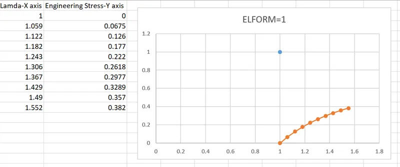
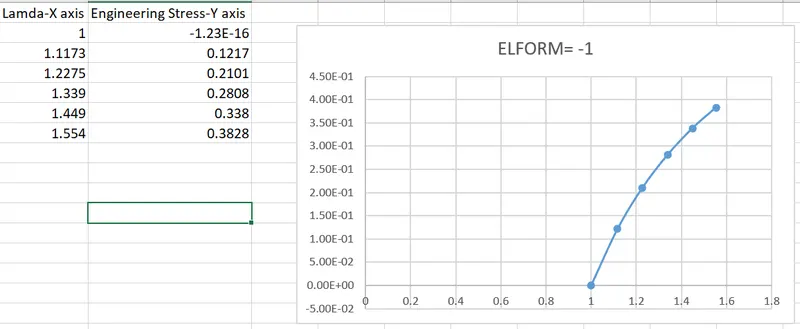
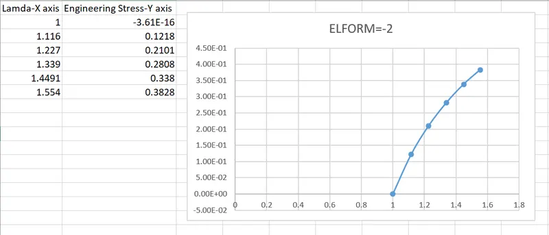
like this way i found the all engineering stress and strains for all ELFORMS. and respective graps shown below.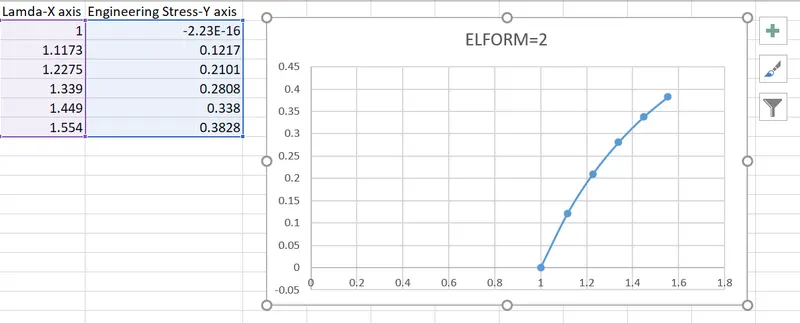
Observation:
1.Implicit methods should be used when the boundary conditions affect the structure slowly, and the effects of strain rates are minimal. Once the increment of stress as a function of strain can be established, geometry can be analyzed using implicit methods.
2.ELFORM=-1,-2 it shows large varion when compared to the ELFORM=1,2 then we need ELFORM =1 shows similar behaviour to graph which is given to us. since ELFORM =2 is fully intergrated is not recommended for all time because computation time stringent and cost effective,ELFORM =1 also giving similar results but less span. if we want fully integrated and accurate results we use the ELFORM=2.
Result:
For given hyperelastic material simulation is done at the various ELFORM( 1, 2,-1,-2).and ELFORM=1 is giving similar results in the uniaxial direction.