Week 12:Project-1-Meshing of Door Inner Panel Challenge
Aim: The Given Component (Door Trim Inner panel Plastic component) Extract Mid surface and Mesh the component with below mentioned Quality Criteria and assign the material and property to the component.
Quality criteria:
Target element length =4
Aspect ratio =5
Skewness =45
Warping =15
Taper =0.5
Minimum Length =2
Maximum length =6
Minimum Quad angle =45
Maximum Quad angle =135
Minimum Tria Angle =20
Maximum Tria Angle =120
Triangle% =10
Theory:
Here the given component door trim inner panel plastic component of a passenger vehicle which has number of the Ribs based on the thickness .Here we do not modeling the hinges because its not attached to the surface rather we model the mounts based on the thickness either offset or curve middle option. when the thickness is below 5mm we follow the 2D shell mesh (Quad, tria ) if the thickness is more than the 6mm then we go for 3D mesh which is Tetra or Hexa elment. Here the mounts having more than 5mm and followed 2D shell method because when two thickness present in the geometry we have follow the either 2D shell or 3D Volume mesh, when its come to attaching the surface its difficult to attach shell elements to 3d elements to avoid this we follow one method in this challenge. When it comes to connections we can attach it Requires nodes not the elements.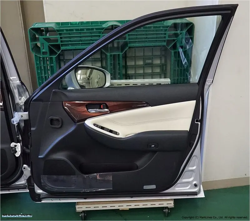
Fig: General Door panel looks
Procedure:
1.Import The Cad Geometry
2.Offset Method(Manual mid)
3.Meshing and Mesh editing tools
1.Import The Cad Geometry:
Here we use two way either we directly use File >Import > Select the geometry to import or we can use file >Open>Model. One done In GUI one click and press F and it will visible to us.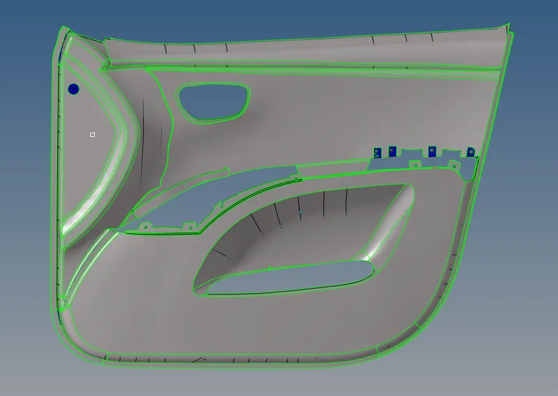
Fig: Imported Cad geometry
2.Offset Method:
This method we can also call it as manual mid surfacing as the name suggest we can use each surface to extract the mid surface. Here the component has ribs which are different thickness so auto mid surface is not possible to extract the mid surface in one shot. From Geometry > surface edit >offset > select the surface and duplicate the surface and check the vector direction based that we can give either positive magnitude or negative magnitude value. Before doing this, we have to set the current component and then proceed for the mid surfacing. Like wise we have to follow the same process until mid-surface is performed for all surfaces. Here I have used the another option as well which is Final edit tools option which is used to extract the mid surface having uniform thickness , this require two surfaces to extract the mid surface . once its done we need to extend the surface to get contacted with adjacent surface here the surface is extended or not to check if extended and intersected then it will be yellow colour and joined which will be in green colour. Here we use use multiple options to extend ,In surface edit we have extend option we can select the surface line and target surface and in the same panel trim with lines here we have to select the surface which is target surface and select the lines or free lines to intersect the surface and set the option normal to surface then press trim, from this we create the line and using that we can create the surface using ruled( geometry >surfaces >ruled. And final edit tools we have option which is imprint we can project the line and create the surface using ruled option from the surface.
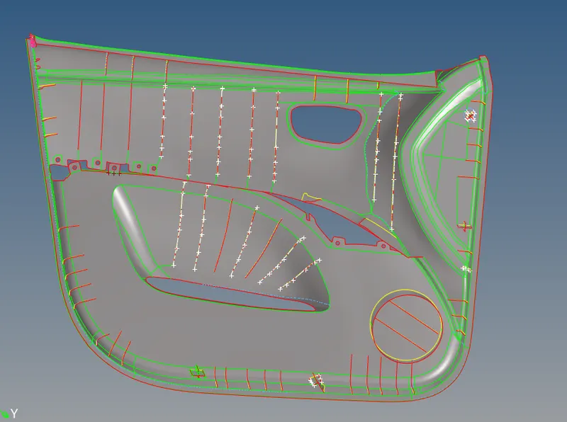
Fig:Extracted mid surface using Offset
3. Meshing and mesh editing tools:
Once mid surfacing is done for all surfaces we can hide the parent geometry and we can apply meshing. Here I have come to know the every time when we apply the meshing on surface we need not to change the current component when different thickness exist in the 2d mesh panel we option which is elements on the surface(2d >automesh >change the target length if default and change the elements on current component to elements on surface from this we can avoid confusing and directly go surface by surface start meshing this will save time and avoid operation. Some areas require some necessary cuts to get good mesh flow. And here I have used the remesh , element optimize and translate ,replace create, combine trias, project all this options are which helped me to get the all quad elements satisfy the given quality criteria. Here we can keep the minimum length is not satisfied we can keep as it is, here I kept some elements not satisfied the minimum length criteria and rest of all satisfied the quality and some areas I have created the trias and to avoid the quality failure.
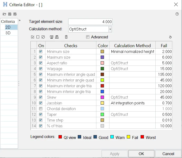
Fig: Quality Criteria of the Door Inner panel
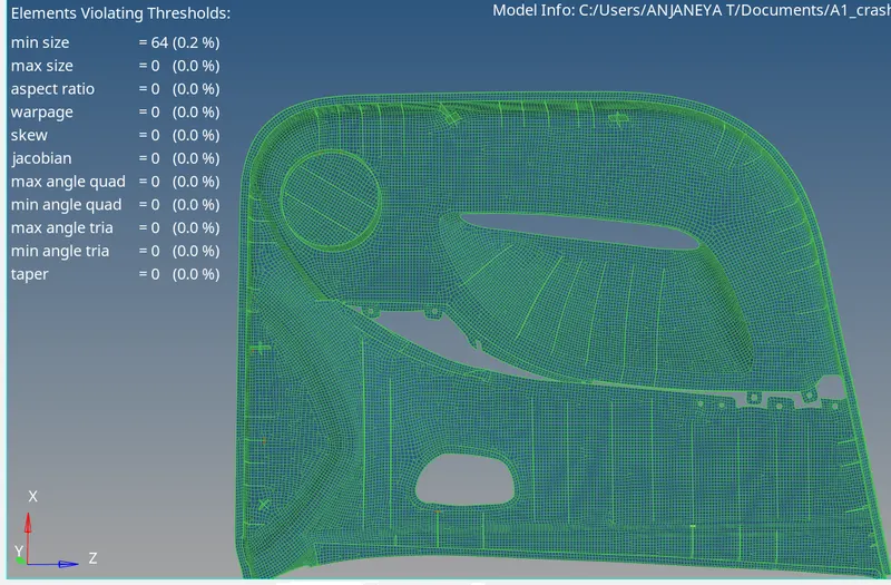
Fig: All the satis fied the Quality Criteria
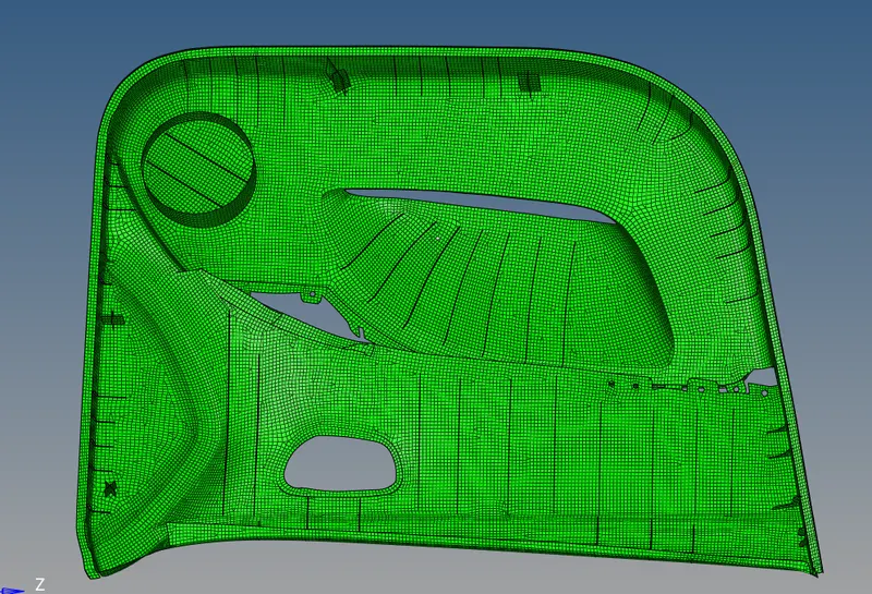
Fig: Material assigned to the component
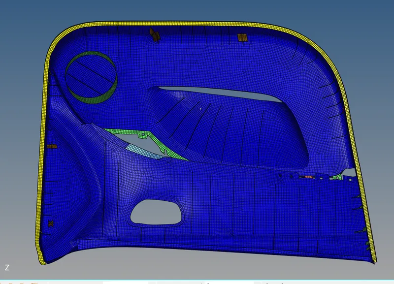
Fig: Component By Property
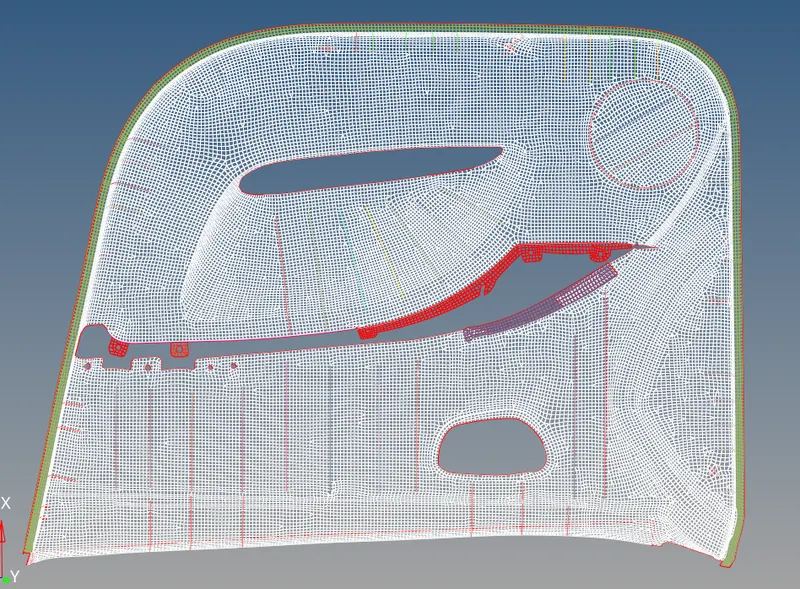
Fig:Component with no free edges in middle
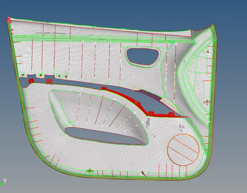
Fig: Final FE along with mid surfaces
Outcomes of the challenge:
1. I have understood cad issues
2.Ability to satisfy the quality criteria that each quad element should passes through
3.Methods to extract the mid surface and the options involved
4.Assign material and property
5. And also using parent geometry which surfaces require to extract the mid surface.
Result:
: The Given Component (Door Trim inner panel Plastic component) Mid surface and Meshing has been done and the component with mentioned Quality Criteria and assign the material and property to the component using Optistruct profile is done