Week - 5 - Modelling Spotwelds
Aim: simulate the given model with the beam and solid element and compare the shear and axial forces between beam and solid element.
Procedure:
1.create the beam element
2.Assign material to the beam ,shell and solid
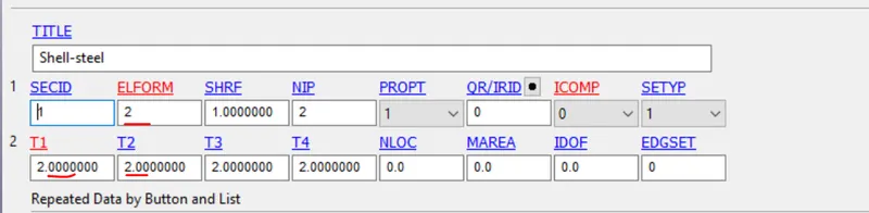
3.After defining the material define the section for beam,solid and shell element.
4.We need to define the contact beam,solid and shell
5.Once contact is defined we need to create the boundary condition
6.Output request
7.Define the termination time from the control.
1.Create the beam element:
To create the beam element from the element and mesh >element generation>beam ,two node set,select the each node from the each part >create so it will create the beam element between two selected node as the it mentioned in the challenge need to create the beam elements along the line its 3 to 7 so based this i have created total 15 beam elements as shown below.
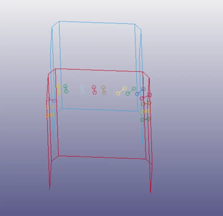
Fig:Beam elements created
2.Assign materai to beam element:
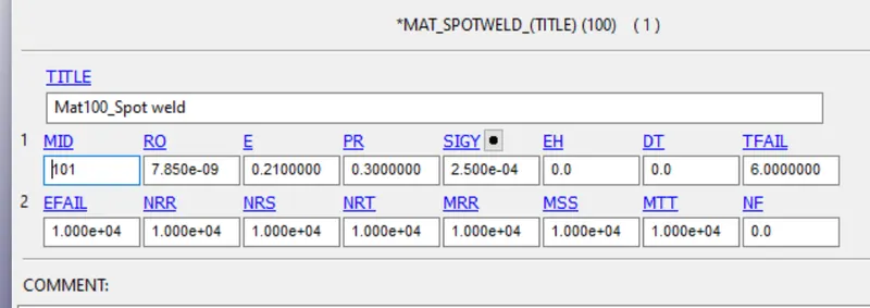
once the beam element is created assign material to the beam and shells . unit is gm mm ms is follwed . material is steal is used here and row,E,nu shown below
Row=7.85E-9 g/mm^3
E =0.21 g/mm^2
nu=0.3
sigy=2.5E-4 g/mm ms^2.
Material for the beam element is 100_spotweld and for the shell material is 001_Elastic material being used.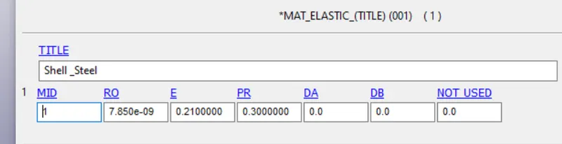
3. Section creation: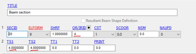
4.Contact defined:
Two type of contacts defined here for the edge to surface contact and the automatic single surface contact defined,bcz once the beam element breaks the shell element should not penetrate each other.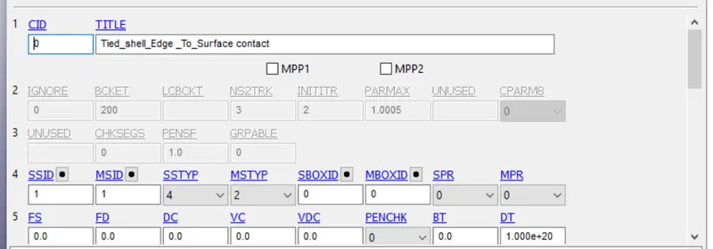
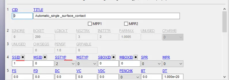
slavesettype is node set we have to select by creating create entity >set>node set,select the nodes connected by the beam eleand masterset is shell parts.
5. Boundary conditions:
here single point constraint(SPS) is used and pesecribed motion set being used in this challenge using boundary >pescribed motion set card is selected and curve defined and created node set is assigned( to apply the displacement to set of nodes create the node set for opposite to the SPC.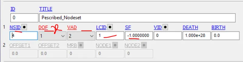
6. Output request:
Ascii(glsat,nodeout,swforces),Binary D3plot. DT is mentioned as 1ms
7. Termination:
To define the control of the termination is need to specify,control >termination,DT=12ms being used. And Tfail is sepecified half of the Termination is taken which is 6ms.
Postprocessing :
Beam Element: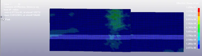
Fig: Vonmises stress plot.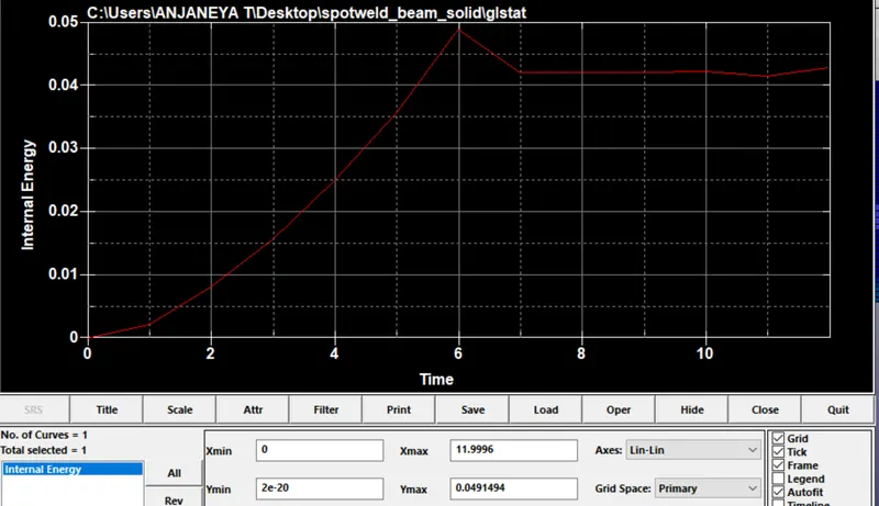
Fig: Internal Energy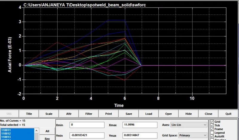
Fig: Axial force(Tension) plot for all beam elements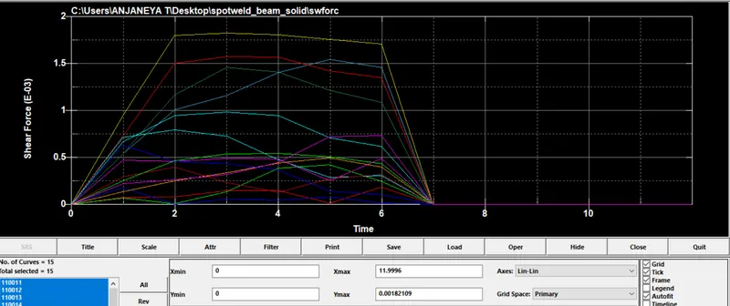
Fig:Shear Force plot for all beam element
For Solid Element: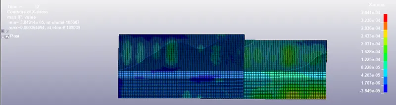
Fig: Vonmises plot for solid element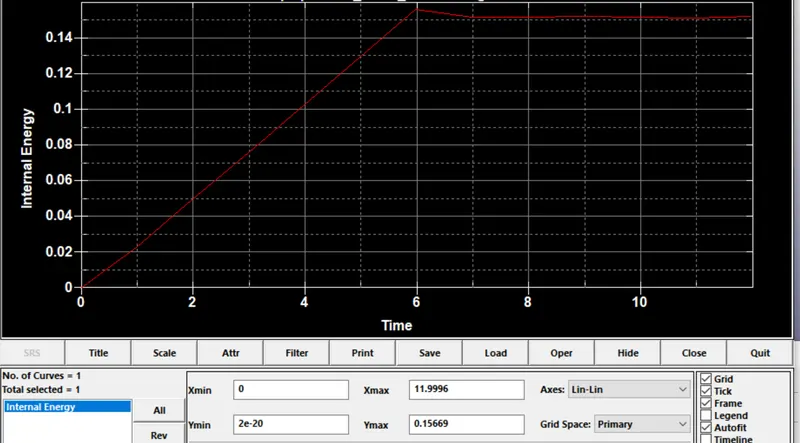
Fig:Internal Energy plot for solid element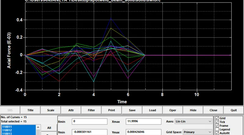
Fig:Axial force(Tension) for solid element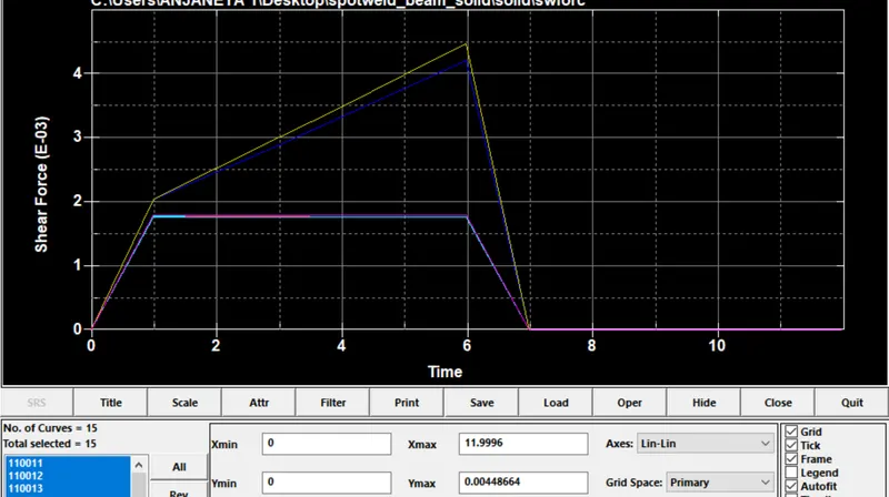
Fig:Shear force for solid element
Observation:
For the Beam element
Internal Energy =0.0491J
Axial force =0.00314 g mm/ms^2
Shear force =0.00182 g mm/ms^2
For Solid Element
Internal Energy = o.15669J
Axial force =0.00042 g mm/ms^2
Shear force =0.004486 g mm/ms^2
For the beam ,element is connected with two nodes it require less energy require to break .And the less shear force is required .Solid element is connected four nodes from each shell part so energy required is more when compare to beam element solid require more energy.
when comes to shear force solid element require more max force to shear. After that once it breaks then force goes decrease as shown. In solid element weld elements are placed closed to each other while breaking closed elements merge as shown in graph.
Result:
Simulation has done for created beam and solid elements and results are ploted and axial,shear force are comapred.