Week 9 - Project - A pillar Design with Master Section
AIM: Create an inner plastic B-Pillar from the given master sections and Class A surface.
Theory:
Pillars:
Pillars are the vertical or near-vertical supports of a car's window area.
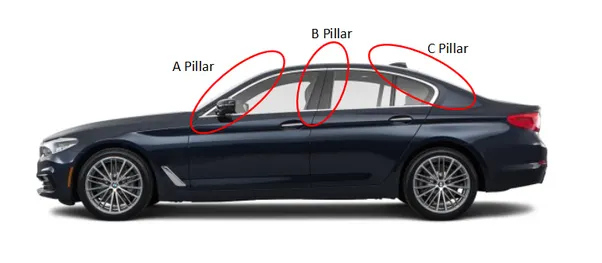
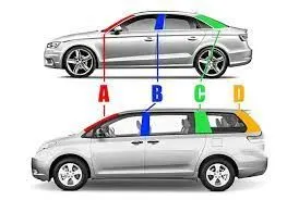
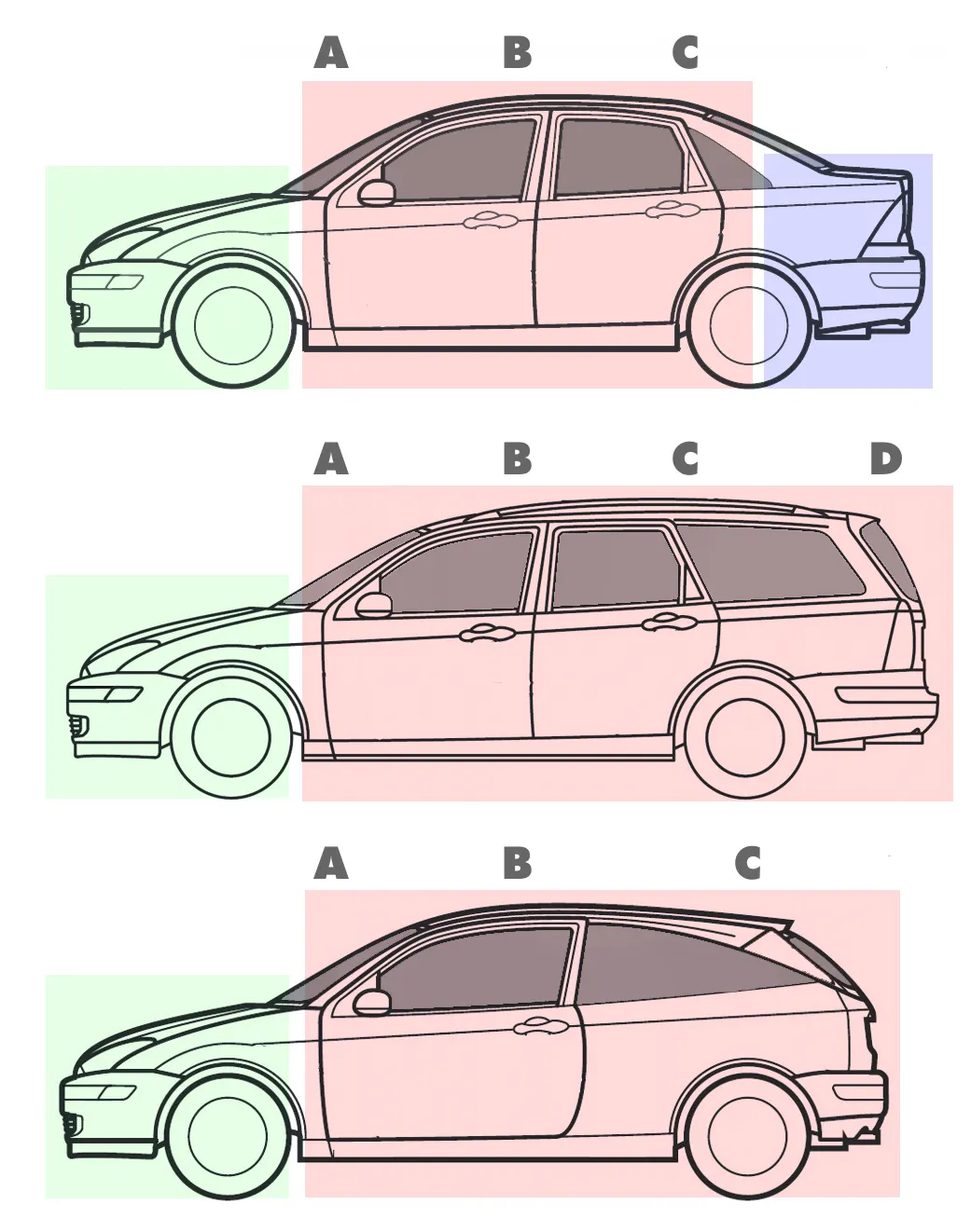
The pillars on a car with permanent roof body style (such as four-door sedans) are the vertical or nearly vertical supports of its window area or greenhouse—designated respectively as the A, B, C and (in larger cars such as 4-door station wagons and sport utility vehicles) D-pillar, moving from front to rear, in profile view.
Basically, there are 3 pillars.
- A pillar:
The pillar or the vertical bar you see holding the windshield from sides.

- B pillar:
The pillar is present in between the rear & the front door.

- C pillar:
This is where your rear window ends but on the body & not on the door.

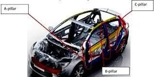
Car pillars are components that support the structure of an enclosed automobile body. This is similar to that of a house with pillars supporting the roof over the floor. Car pillars are designed to stand in near vertical or inclined positions to support the roof.
The consistent alphabetical designation of a car's pillars provides a common reference for design discussion and critical communication. This is used by insurance companies to identify damaged components and rescue teams employ pillar nomenclature to facilitate communication when cutting wrecked vehicles, as when using the jaws of life.
The A-pillars on each side of the windshield come up to be joined together by the header rail across the top of the windshield.
The B pillars are sometimes referred to as "posts" (such as a two-door or four-door post sedan).
Body pillars are critical in providing strength to an automobile body. As the most costly body components to develop or re-tool, a vehicle's roof and door design are a major factor in meeting safety and crash standards. Before safety standards, pillars were typically thin. The design of body pillars has changed with regulations that provide roof crush protection. Standards in the United States were introduced in phases starting in 2009 that require enclosed passenger cars to be able to support from 1.5-times to 3.0-times the vehicle's unloaded weight on its roof while maintaining headroom (survival space) for occupants.
This has meant designing thicker roof pillars that not only provide sufficient strength, but also to incorporate padding and airbags. However, thicker A-pillars block the field of vision and create blind spots). Some designs employ slimmer, chamfered A-pillars on each side of the windshield to help improve driver vision and through the use of stronger alloy steel. The objective of this construction is to meet safety standards and offer crash protection.
One of the important design elements of modern cars is the A-pillar because its location and angle impact the shape of the front of the car and the overall shape of modern vehicles or what designers call "volume." For example, more forward positioned A-pillars provide for increased interior room and make for less angle and visual difference between the hood and windshield. This arrangement makes the side view of a car look aerodynamic. The A-pillars that are positioned further back on a vehicle are most often found on rear-wheel drive and SUV models. This arrangement provides a greater hood to windshield angle as well as achieving a bigger field of view for the driver, but at the disadvantage of encroaching on interior space.
In the case of the B (or center) pillar on four-door sedans, the pillar is typically a closed steel structure welded at the bottom to the car's rocker panel and floorpan, as well as on the top to the roof rail or panel. This pillar provides structural support for the vehicle's roof panel and is designed for latching the front door and mounting the hinges for the rear doors. As "perhaps the most complex of all the structures on the vehicle", the center or B-pillar may be a multi-layered assembly of various lengths and strengths.
Closed vehicles without a B-pillar are widely called hardtops and have been available in two- or four-door body styles, in sedan, coupe, and station wagon versions. Designs without a center or "B" pillar for roof support behind the front doors and rear side windows offer increased occupant visibility, while in turn requiring underbody strengthening to maintain structural rigidity. The need for stronger roof structures meant replacing the pillar-less designs with a rigid B-pillar such as the two-door AMC Matador line. To continue capitalizing on the popularity of the design, General Motors broadened their definition of "hardtop" during the early 1970s to include models with a B-pillar although: "up to then, everybody thought a hardtop was a car without a center pillar." The "Colonnade" mid-sized General Motors models were so named because of their pillared structure designed to new rollover protection standards, but marketers continued to advertise them like the true hardtop predecessors. By the 1980s the full-size Chrysler was the last design without a B-pillar and with opening front and rear side windows.
The C-pillar is the rearmost on two- and four-door sedans and hatchback cars and has served as an opportunity for automobile designers "to introduce a little 'design flair' to what would otherwise be a fairly nondescript side view." Most conventional C-pillars are rearward sloping, but reverse-angled have been used to differentiate their designs. Because many modern cars are similar in side view, the designs of the C-pillar have "become an area for stylistic whimsy."
Designs of the D-pillar typically found on station wagons and SUVs have also undergone a transition from function to more of a styling element. As crossover vehicles look similar, "the D-pillar is the only opportunity for any distinction."
Pillars are implied, whether they exist or not; where a design's greenhouse features a break between windows or doors without vertical support at that position, the non-existent pillar is "skipped" when naming the other pillars. Thus a two-door hardtop or a three box designed coupé could have its rearmost pillar called the C-pillar even in the absence of a B-pillar. Conversely, additional doors, such as on limousines, will create additional B-pillars; the B-pillars are then numbered, B1, B2, and so forth.
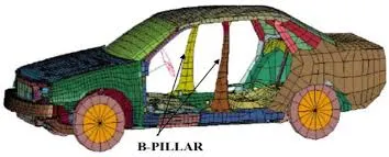
In addition to the pillar nomenclature derived from viewing an automobile in profile, some older cars have a two-part windshield or a split rear window, with the two halves separated by a pillar. Posts for quarter windows (a smaller window typically between the front window and the windshield) are not considered a named pillar.
GIVEN:
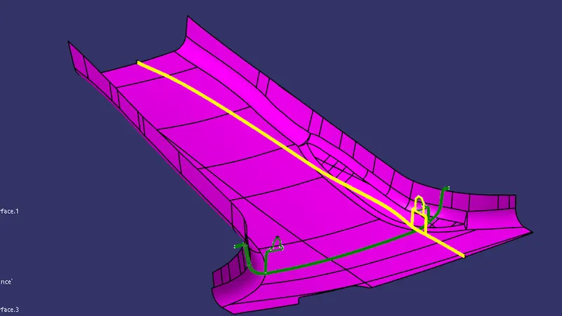
We are given two master sections and a Class A surface.
The master sections seem to give an abstract idea of the thickness of the material and the features to be given in Class B.
NOTE: Given Master section in green color is wrong so necessary adjustments were made to procure the Solid part as needed.
PROCEDURE:
- Create a Tooling Axis for the part.
- Create Class B and Class C surfaces and trim.
- Do Draft analysis.
- Create the features according to the Master section.
- Do final Draft analysis.
MAIN TREE: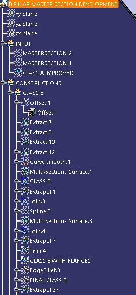
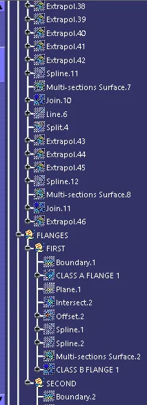
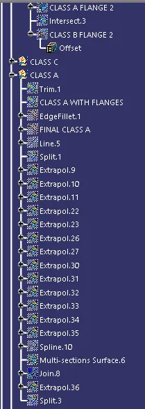
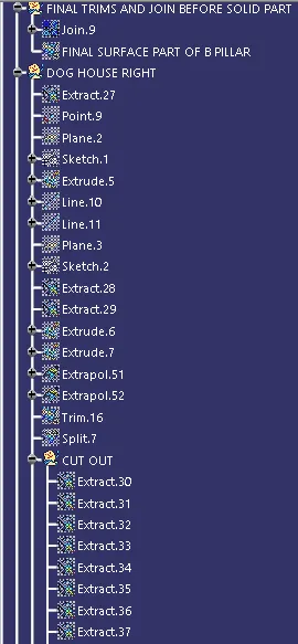
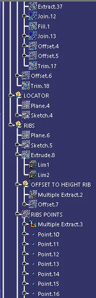
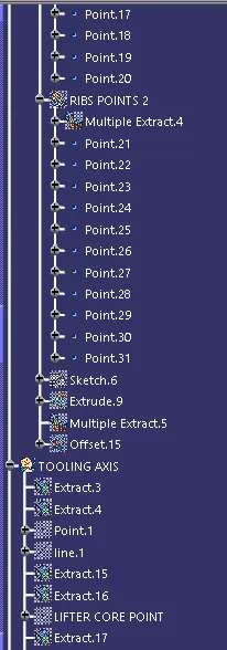
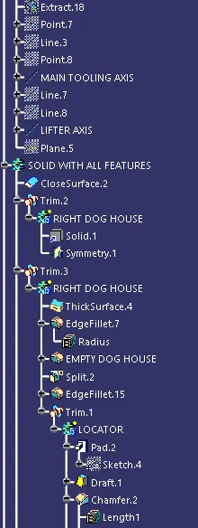
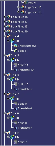
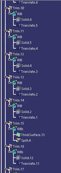
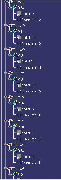
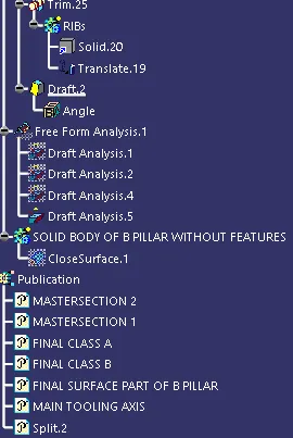
1: Create a Tooling Axis for the part.
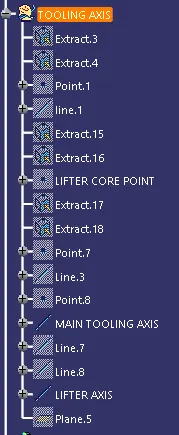
- Using the sides of the two master section 2 lines each are created and a midpoint between the lines is marked.
- 2 bisecting lines are created at the midpoints for each pair of lines created.
- Finally, the two lines are again bisected to get the MAIN TOOLING AXIS.
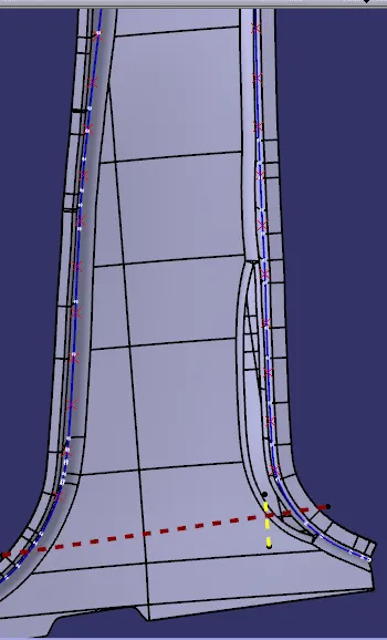
- Similarly, the Lifter Core Axis is also created by taking master section 2 as input and bisecting the lines at the lifter core point.
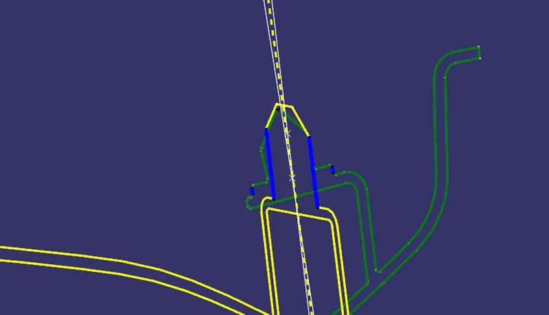
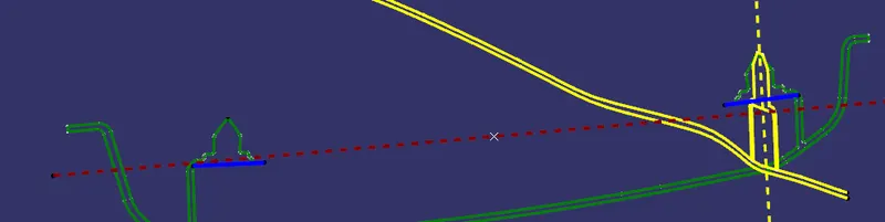
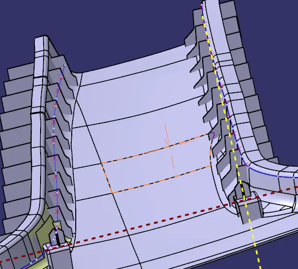
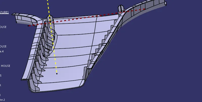
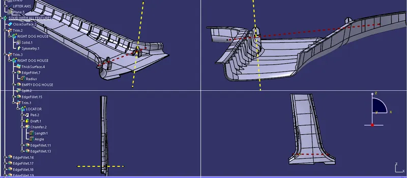
- The below figure shows the blue lines extracted from the master section to create the tooling axis.
- The yellow line is the Main Tooling Axis while the Brown Line is the Lifter core Axis.
2: Create Class B and Class C surfaces and trim.
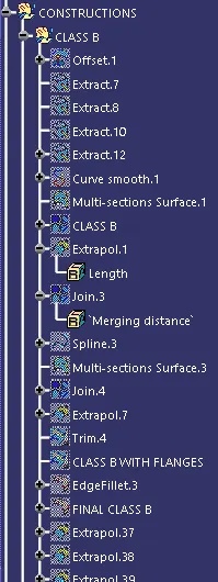
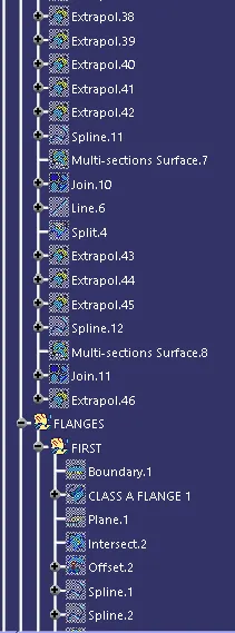
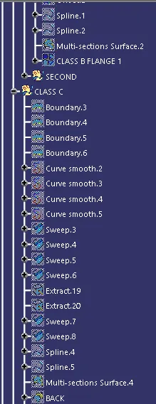
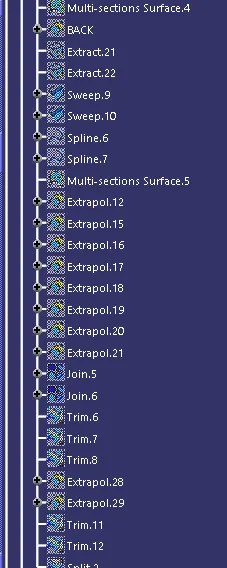

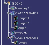
For Class B:
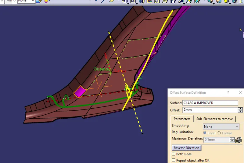
- Create an offset of class A with an offset length of 2 mm.
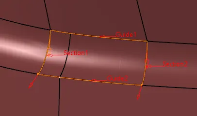
- If any patch does not happen just create a multi-section of it.
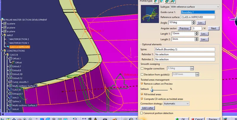
- To create Flanges create a boundary of class A then Sweep it with the horizontal master section angle.
- Offset the same for class b surface and trim them.
- Same as above if any patch does not get created just multi-section it.

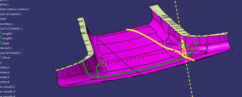
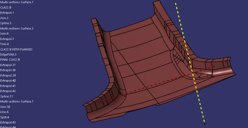
For Class C:
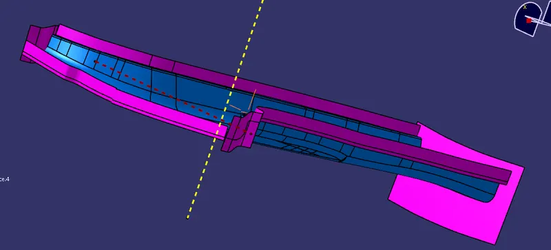
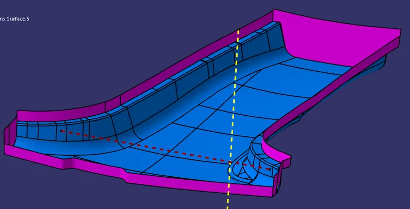
- Create Boundaries around class A but in separate patches, so that error does not occur while sweeping it in the draft direction.
- Then smooth curve to create fewer patches of vertices getting converted into unwanted lines on Class C.
- Sweep it along the Main tooling axis in the draft direction option at 3 degrees.
- Extrapolate all surfaces and trim them to get the desired surface output.
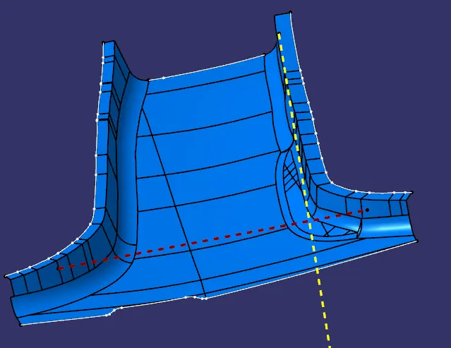
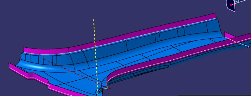
For Final Trim and join:
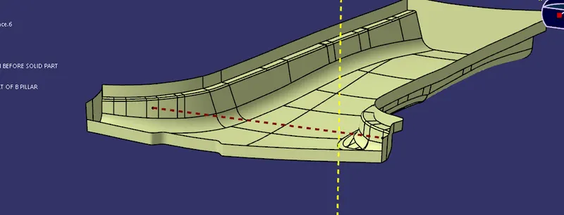
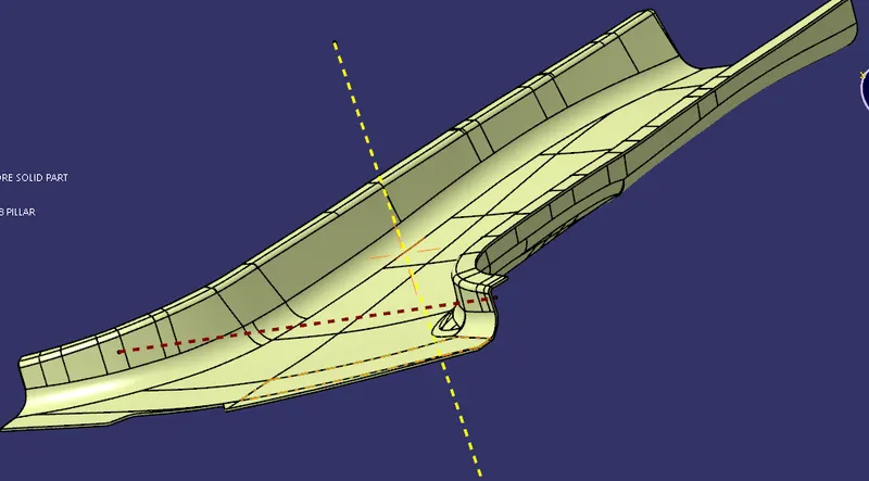
- Extrapolate both Class A and Class B surfaces to avoid the wireframe error as we smooth curved the class C surface. Note: IF not possible then split the surfaces and join them.
- Then Trim the Class A and Class C surface and finally with Class B.
3: DRAFT Analysis:
CLASS A Draft analysis.
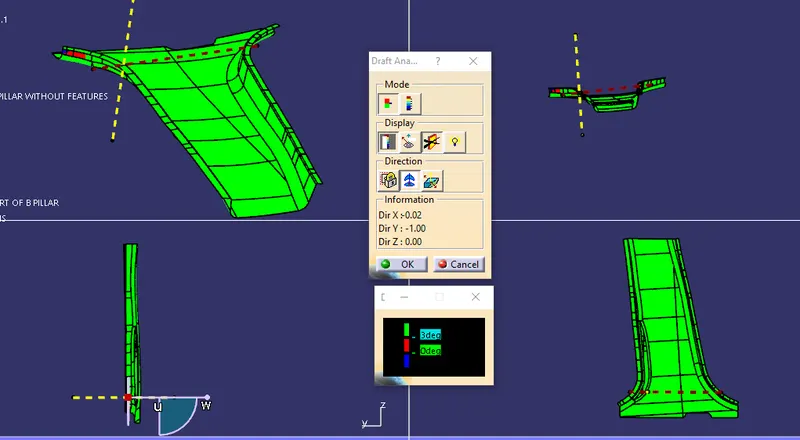
Solid body without features Draft Analysis:
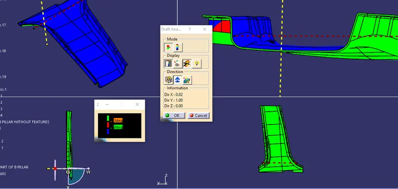
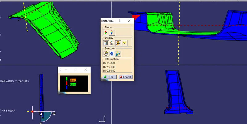
4: Create B side Features.
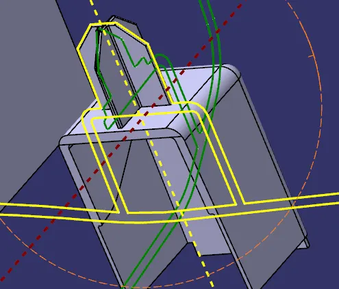
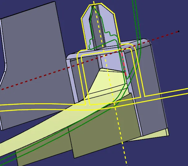
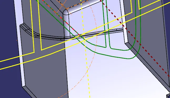
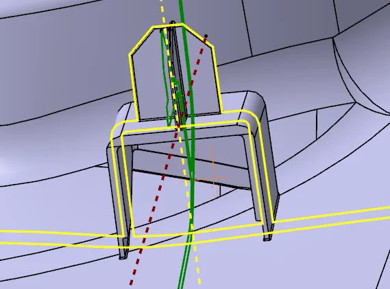
For DogHouse with 4 Way Locator:
Procedure:
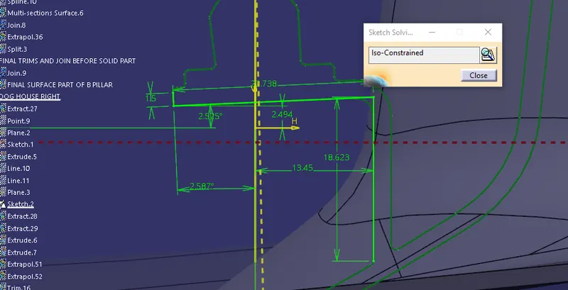
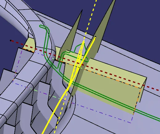
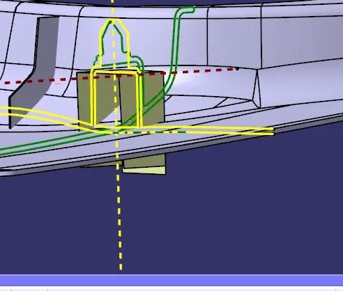
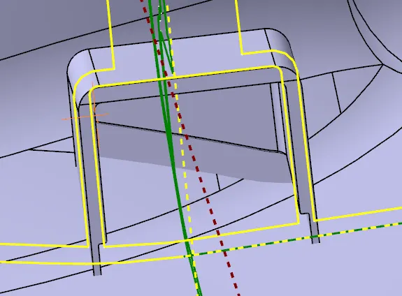
- Extract the necessary details of the master section for creating a Doghouse.
- Create a sketch for the outer box of the doghouse.
- Extrude the surface and trim it with the inner and outer walls of the other master section.
- Use a thick surface to give the surface a 2 mm thickness and create a solid of it.
- Use Edge fillets of 1 mm and 3 mm as per the master section.
- To create a Coring inside which we need to do according to the design rules the inside wall thickness should be 1mm and a draft of 0.5 degrees with a coring height of 3-6 mm from the base.
- Also, the inside fillets which are not mentioned should be around 0.25mm.
- Using the master section extract the longer edge and measure it.
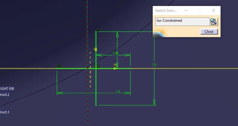
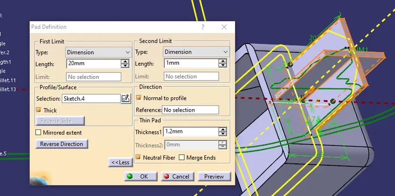
- Now create a sketch with the cross of it on top of the Doghouse.
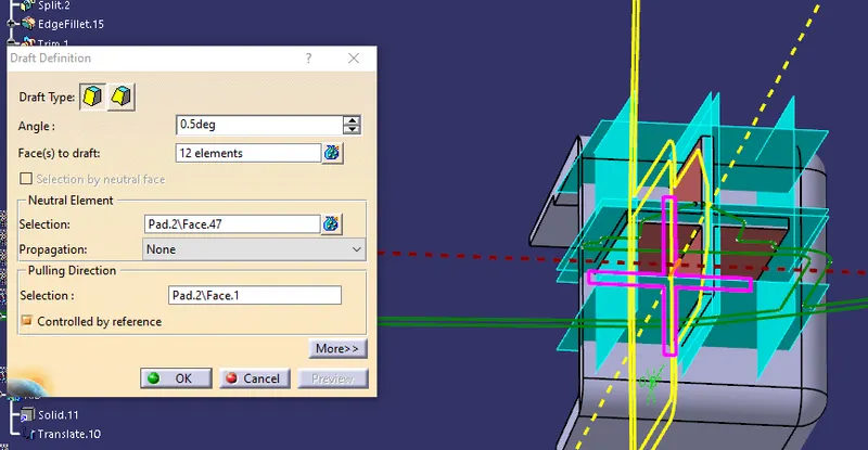
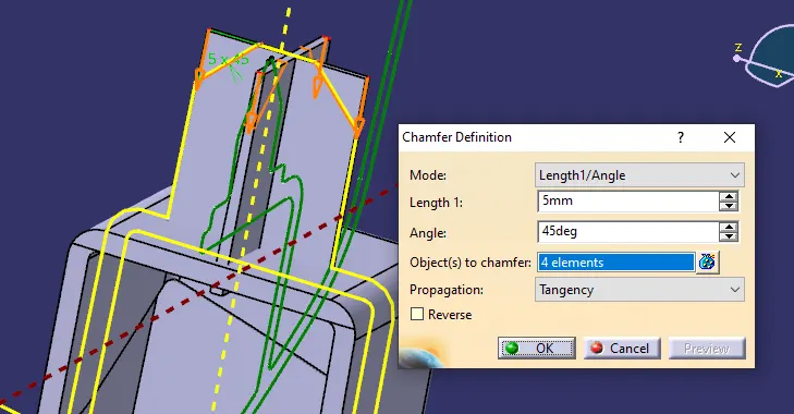
- Maintaining all the design rules for the 4-way locator, Height is given as 20mm and chamfer of 5mm X 45 degrees, Neutral thickness of 1.2 mm is taken fillets of 0.3 mm are taken along with the Draft angle of 0.5 degrees.
- Finally, using the union trim command of boolean operations we get the final doghouse with a 4-way locator.
For RIBS:
Procedure:
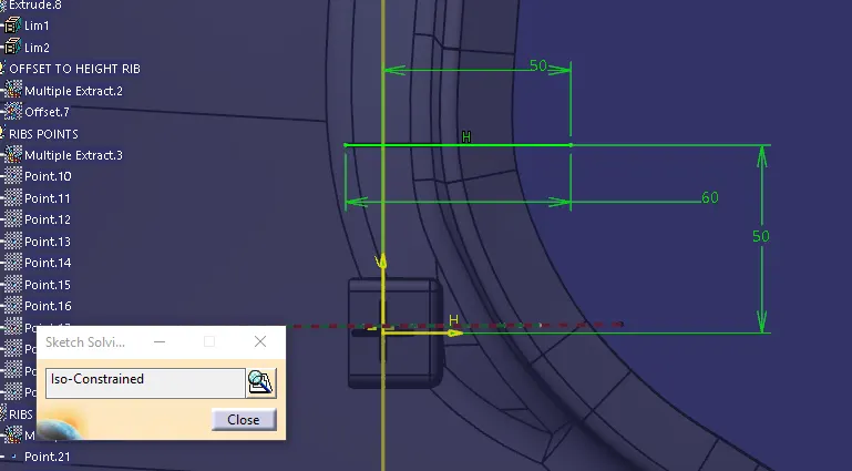
- Create a Sketch at 50 m from the dog house in the Z direction.
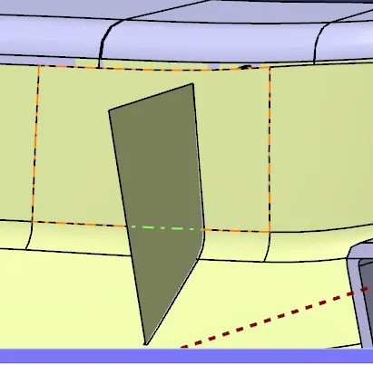
- Give adequate length and extrude the surface along Y and thicken both sides up to 0.4 mm and a draft of 0.5 degrees according to design rules.
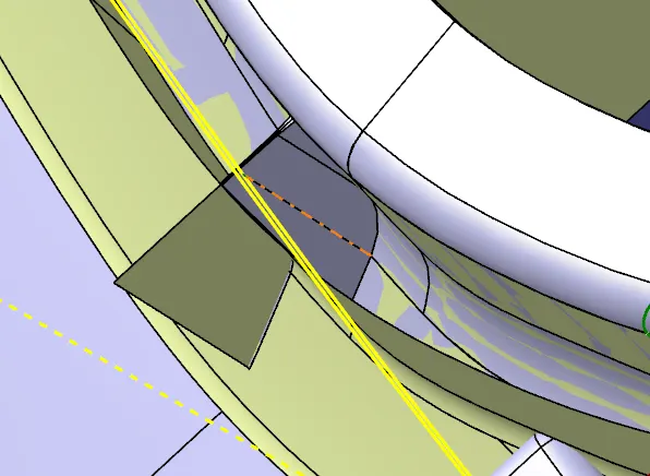
- Extract and offset the surface around the first rib and split the rib.
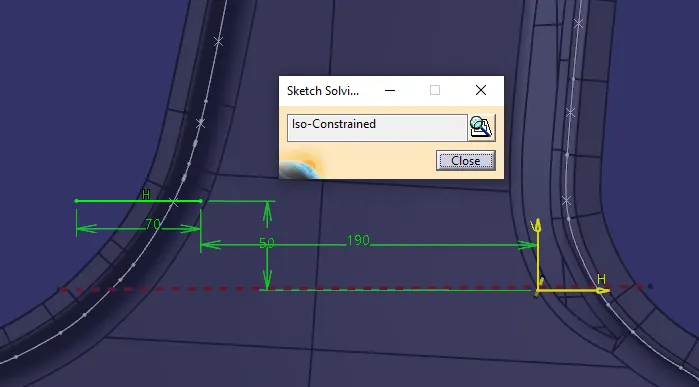
- Now using the boundaries of Class B create multiple points at 50 mm equidistant and copy and paste with link command
- Use translate to move each of the ribs, Do the same steps for the other side ribs.
- Finally, Union trim it with the part body to get the final body
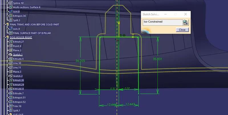
5: Final Draft Analysis.
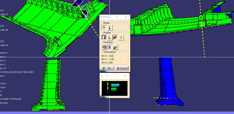
DRAFT ANALYSIS of Final part along main tooling axis for ribs:
For DOG house along with lifter core :
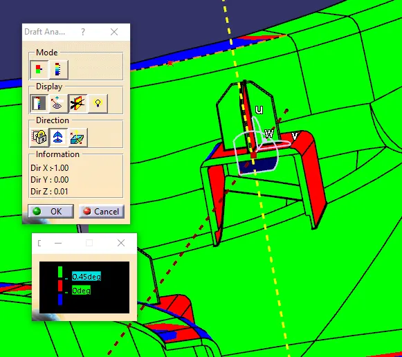
Hence the model is accurate & the analysis is conducted successfully.