Week 7 State of charge estimation
We open the required model:
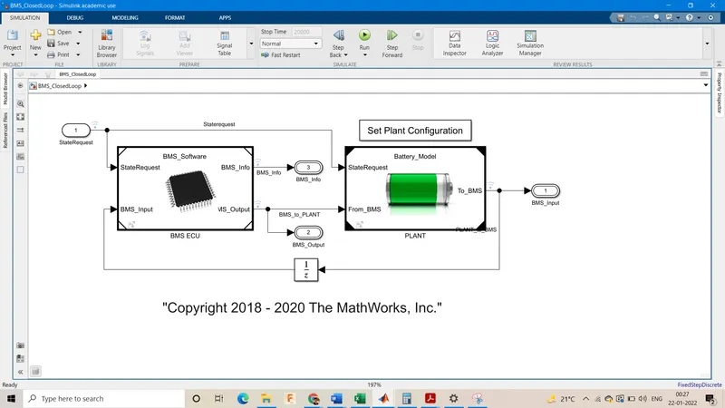
Go inside the Set Plant Configuration
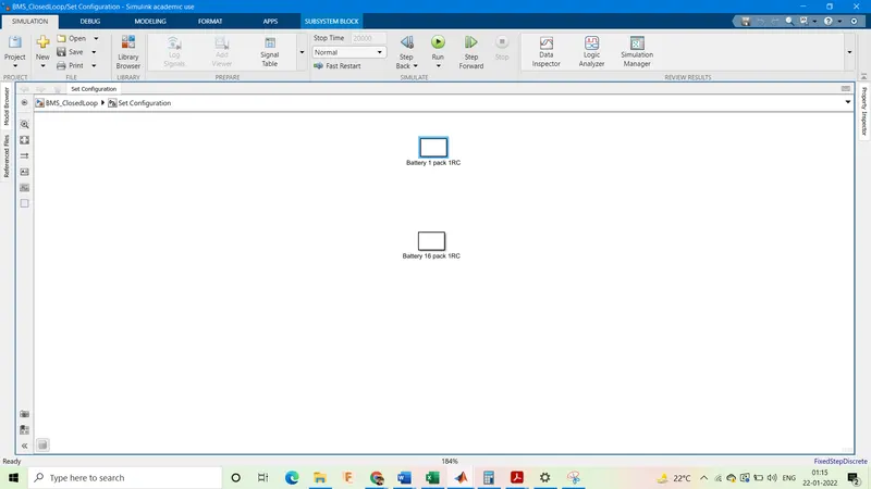
Double Click on the Battery 1 pack 1RC.
Test Case 1:
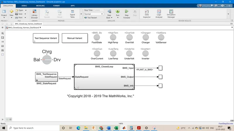
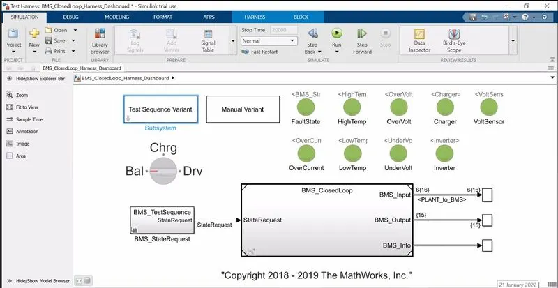
This is the BMS system
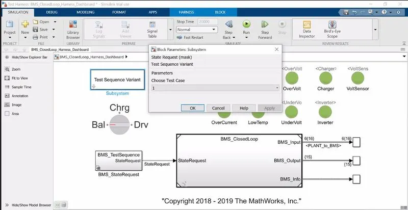
Double Click on the test sequence variant & select test case 1.
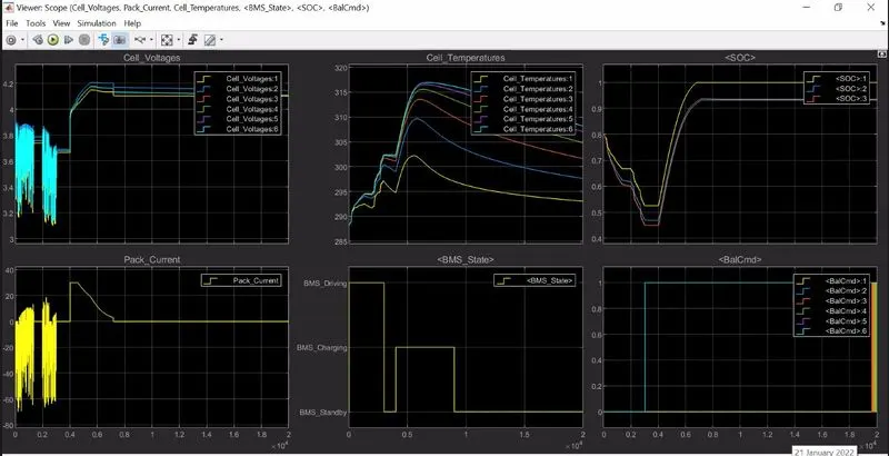
We get the above graphs for the test case 1, where we observe that the cell voltages settle at around 4.1V with some minor diffrences between them. The cell temperatures vary quite substancially for all the cells & this setup would require an active cooling system. The state of charge shows a major difference about 8%, this could be probably due to the temperature difference between the cells & would be solve with the cooling system itself. The BMS State varies between driving, charging & standby as the time progresses. The peak current for this system is at about 30A for discharging & 40A for charging & settles to 0 for the standby mode.
Test Case 2:
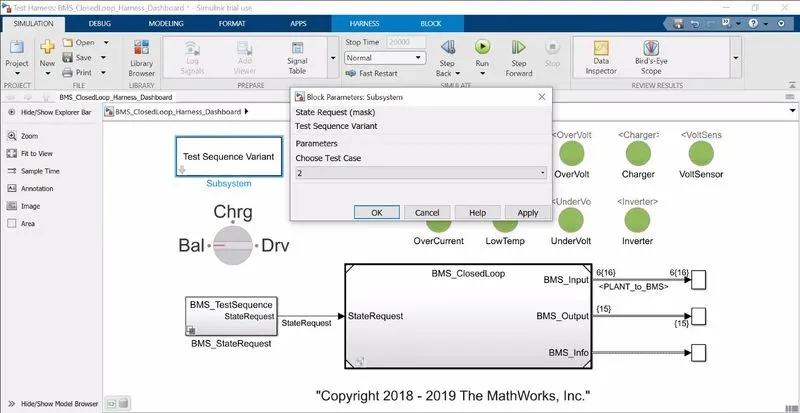
We choose the test case 2
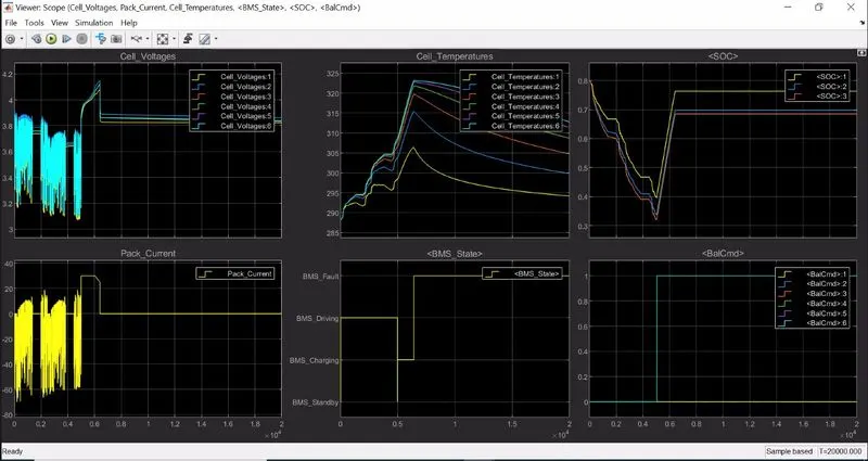
We get the above graphs for the test case 2, where we observe that the cell voltages go to about 4.1V during dischrage then drop & settle at around 3.8V with some minor diffrences between them. The cell temperatures vary quite substancially for all the cells & this setup would require an active cooling system. The state of charge shows a major difference about 9%, this could be probably due to the temperature difference between the cells & would be solve with the cooling system itself. The BMS State varies between driving, charging & standby as the time progresses. The peak current for this system is at about 30A for discharging & 40A for charging & settles to 0 for the fault mode.
Test Case 3:
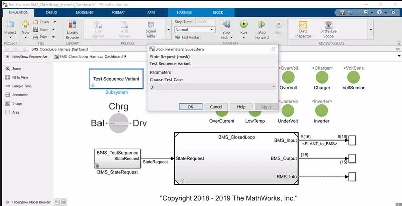
We choose the test case 3.
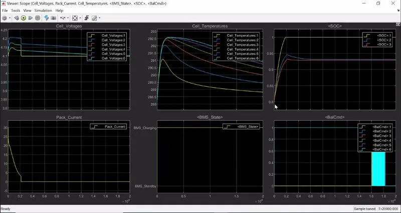
We get the above graphs for the test case 3, where we observe that the cell voltages go to about different voltages between 4.1V-4.25V during chraging then drop & settle at around 4.1V with some minor diffrences between them. The cell temperatures vary quite substancially for all the cells & this setup would require an active cooling system. The state of charge shows a major difference about 7.5%, this could be probably due to the temperature difference between the cells & would be solve with the cooling system itself. The BMS State varies between driving, charging & standby as the time progresses. The peak current for this system is at about 30A & reduces gradually over time & then stays zero for the rest of the time.
Coulomb Counting:
The Coulomb counting method measures the discharging current of a battery and integrates the discharging current over time in order to estimate SOC .Coulomb counting method is done to estimate the, which is estimated from the discharging current, and previously estimated SOC values. SOC is calculated by the following equation:
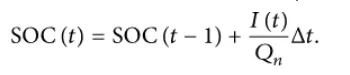
But there are several factors that affect the accuracy of Coulomb counting method including temperature, battery history, discharge current, and cycle life.
Modified Coulomb Counting Method
To improve the Coulomb counting method, a new technique called modified Coulomb counting method is proposed. The modified Coulomb counting method uses the corrected current to improve the accuracy of estimation.
The corrected current is the function of discharging current. There is a quadratic relationship between the corrected current and discharging current of battery.
By practice of experimental data, corrected current is calculated by the following form:
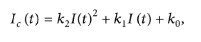
where k0,k1 & k2 are constant values obtained from the practice experimental data.
In modified Coulomb counting method, SOC is calculated by the following equation:
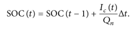
The experimental results show that the accuracy of the modified Coulomb counting method is superior to the conventional Coulomb counting method. But there are several factors that affect the accuracy of Coulomb counting method including temperature, battery history, discharge current, and cycle life .
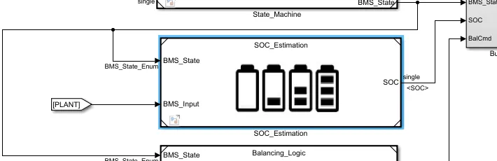
In the BMS ECU block there is a block dedicated to SoC estimation.
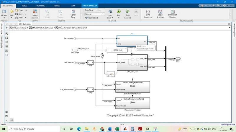
Inside this block there exists a block for coulomb counting.
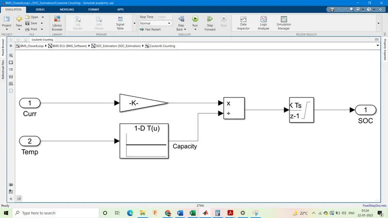
This assembly of blocks inside coulomb counting subsystem take current & temperature as the input & integrate them over time & divide the capacity by total capacity of the system to give the percentage state of charge.
Advantage of coulomb counting method is its simplicity and low computational cost.
Reference: https://in.mathworks.com/matlabcentral/fileexchange/72865-design-and-test-lithium-ion-battery-management-algorithms