Project 1 Mechanical design of battery pack
About the cell:
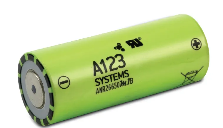
A123’s high-performance Nanophosphate® lithium iron phosphate (LiFePO4) battery technology delivers high power and energy density combined with excellent safety performance and extensive life cycling in a lighter weight, more compact package. Our cells have low capacity loss and impedance growth over time as well as high usable energy over a wide state of charge (SOC) range, allowing our systems to meet end-of-life power and energy requirements with minimal pack oversizing.
A computational efficient battery pack model with thermal consideration is essential for simulation before real-time embedded implementation. The proposed temperature-dependent battery model (LiFePO4 battery cell, ANR26650M1-B from A123 Systems) will increase the lifespan of the battery. The simulation outputs are validated by a set of independent experimental data at a different ambient temperature using the dataset collected at 5 °C, 15 °C, 25 °C, 35 °C and 45 °C.
Applications
COMMERCIAL SOLUTIONS
Advanced lead acid replacement batteries for:
+ Datacenter UPS
+ Telecom backup
+ IT backup
+ Autonomously guided vehicles (AGVs)
+ Industrial robotics and material handling equipment
GOVERNMENT SOLUTIONS
+ Military vehicles
+ Military power grids
+ Soldier power
+ Directed energy
GRID SOLUTIONS
+ Frequency regulation
+ Renewables integration
+ Reserve capacity
+ Transmission and distribution
TRANSPORTATION SOLUTIONS
Hybrid, plug-in hybrid and electric vehicle battery systems for:
+ Commercial vehicles
+ Off-highway vehicles
+ Passenger vehicles
Characteristics
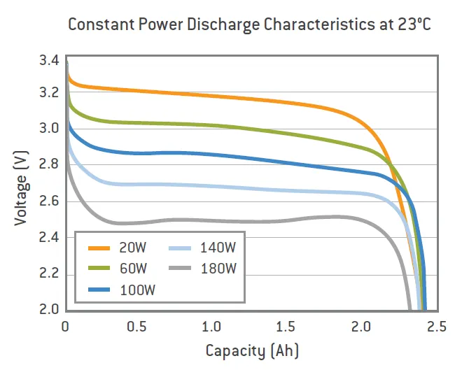
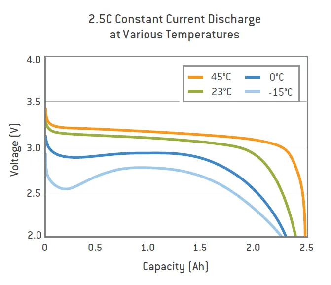
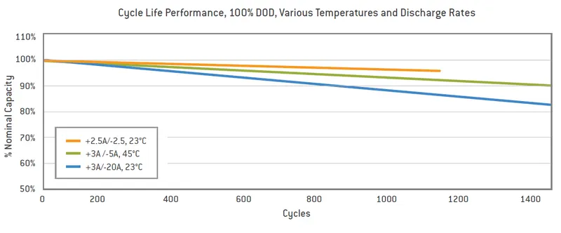
This high-performance Nanophosphate lithium iron phosphate (LiFePO4) battery technology delivers high power and energy density combined with excellent safety performance and extensive life cycling in a lighter weight, more compact package. Our cells have low capacity loss and impedance growth over time as well as high usable energy over a wide state of charge (SOC) range, allowing our systems to meet end-of-life power and energy requirements with minimal pack oversizing.
Mechanical Design:
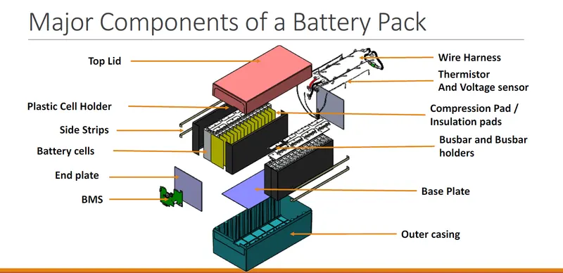
Components:
1. Base Plate
2. Side Strips
3. End Plate
4. Busbars
5. Outer Casing
The battery is to be of 18KW
Assume required voltage to be 300V
So the Ah capacity would be of 18000/300=60Ah
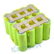
Considering a mPnS combination
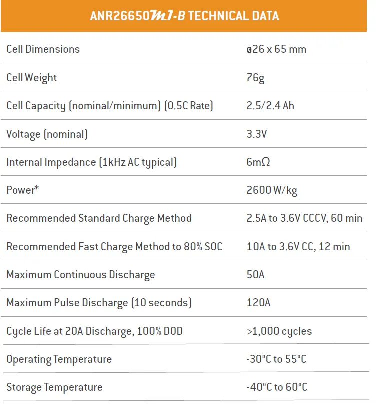
m=60/2.5=24
n=300/3.3=90.9~91
Total cells =m*n=24*91=2184 cells
Weight of 1 cell=76g=0.076kg
Weight of 2184 cells=2184*0.076=165.984 kg~166kg
Width required= m*dia of cell=24*26= 624mm
Considering width to be 650mm for the pack for clearance & other connections.
So Actual width(W)=650mm
Length=n*Dia of cells=91*26=2366mm
Considering length to be 2400mm considering clearance & other connections
Actual Length(L) =2400mm
The Height of each cell is 65mm, but considering connections & clearnace let the height of the pack be 70mm
H=70mm
So the base plate dimensions would be 2400*650
Considering the simply supported base plate
Volume= 2400*650*70= 109.2*10^5 mm^3
Stress on plate= Total Load/Area= Mass*g/Area=166*9.81/2400*650=0.0020877 N/mm^2
Material Selection:
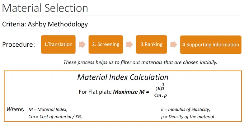
Materials used for base plate are Mild Steel or Aluminium 6061
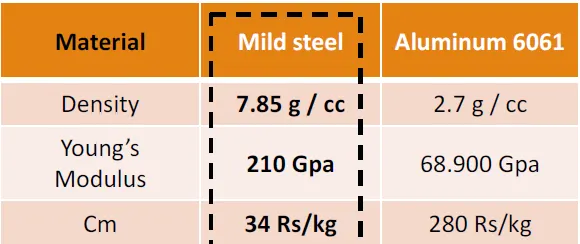
M(steel)= (E)^(1/3)/(Cm*Density)=(210*1000)^(1/3)/(34*7.85*10^(-6))= 22.27*10^4
M(Al)= (E)^(1/3)/(Cm*Density)=(68.9*1000)^(1/3)/(280*2.7*10^(-6))= 5.422*10^4
As we need to Maximize M by Ashby's Methodology we choose Mild Steel as our Material
Properties of Mild Steel
Young's Modulus(E)=210Gpa
Max Yield Strength=350Gpa
Poisson's ratio=0.3
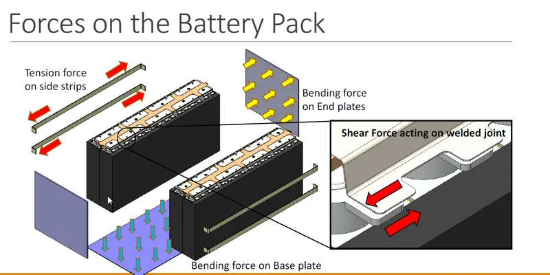
Forces on battery pack
1. Bending force on base plate
2. Tension on side strips
3. Bending force on end plates
4. Shear force on welded joint
Now,
For base plate thickness we will use Kirchoff's equation for the base plates:
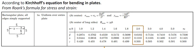
here a=2400 , b=650
a/b=3.69~4 (nearer to 4)
From the given table
Beta=0.741
Alpha=0.14
gamma=0.502
ymax=-Alpha*Stress*b^4/(E*t^3); %ymax is the maximum deflection
Conventionally ymax is taken to be about 1mm in downward direction i.e -1mm (Assumption)
t=(-Alpha*Stress*b^4/E*ymax)^(1/3)=(-0.14*0.0020877*650^4/210000*(-1))=6.28mm~7mm
Hence the thickness of the base plate is 7 mm
Now, Calculating Max Stress
Max Stress= Bending stress=Beta*Stress on plate*b^2/t^2
=0.741*.0020877*650^2/7^2
=13.3388 N/mm^2=13.3388 Mpa
The allowable stress is of 350 Mpa & 13.3388<350 Mpa
Hence for the calculated thickness the design is safe under maximum stress.
Considering the base plate takes maximum stress, Mild Steel can be used for all other componets like end plate, side plate & outer casings as well as well.
Dimensions for end plates would be 650*70
Dimensions for side plate would be 2400*70
Outer casing would be a shell of volume slightly greater than 2400*650*70 mm^3.
Vibration Analysis:
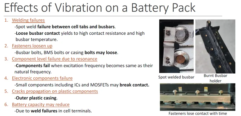
To avoid the massive damage due to vibrations, design needs to be done to avoid resonance
Resonance freq= (Stiffness Constant/Mass)^(1/2)
Consider the Stiffness Constant of the pack to be K=80000 N/m
Resonance freq= (80000/166)^(1/2)=21.95 rad/s
Would need to avoid this resonance frequency & its modes by modifying the stiffness constant if required.
Designing for crash
High value resistance is added in parallel path of battery, which gets connected by BMS command & can dissipate all energy in 5-10 minutes in case of a crash.
The system also has a fire supression system in place.
Battery Packaging:
The battery casing has to provide the mechanical and electrical interfaces to the product it is designed to power as well as to contain all the components outlined above. The simplest and least expensive packaging for small batteries is shrink wrap or vacuum formed plastic. These solutions are only possible if the battery is intended to be completely enclosed by the finished product. Injection moulded plastics are used to provide more precision packs. For enclosed packs designs using a minimum of materials are based around which a plastic frame holds the components in place thus minimising the cost, the weight and the size of the pack. The overall product cost can be further reduced by using
insert mouldings in which the interconnection strips and the terminals are moulded into the plastic parts to eliminate both materials and assembly costs. Over moulding may also be used to encapsulate and protect small components or sub-assemblies. In some designs the battery pack forms part of the outer case of the end product. The colours and textures of the plastic must match the plastics of the rest of the product even though they may come from a completely different supplier. These designs are usually required to incorporate a mechanical latch to hold the battery in place. Again, this latch as well as the terminals must interface with plastic parts from a different supplier so high precision and tight tolerances are essential. ABS polymers are the materials typically used for this purpose.
Batteries for traction applications are usually very large and heavy and subject to large physical forces as well as vibrations so substantial fixings are required to hold the cells in place. This is particularly necessary for batteries made up from pouch cells which are vulnerable to physical damage. Automotive battery packs must also withstand abuse and possible accidental damage so metal casings will normally be specified. The metal pack casing also serves to confine any incendiary event resulting from the failure of a cell or cells within the battery and to provide a measure of protection for the user. At the same time the case must also protect the cells and the electronics from the harsh operating environments of temperature extremes, water ingress, humidity and vibration in which these batteries work.
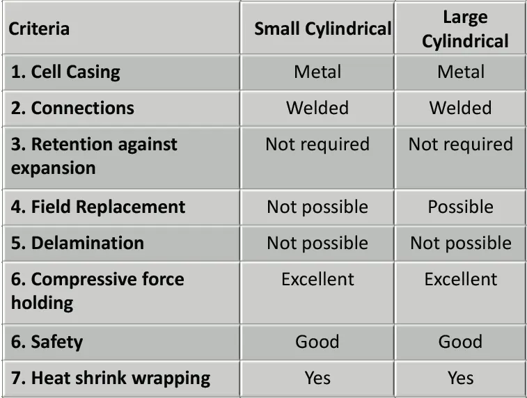
Usually the complete pack is replaced when the battery has reached the end of its useful life. In certain circumstances however, for instance when the pack incorporates a lot of electronic circuits, it may be desirable to design the pack such that the cells within the pack can be replaced. If the design requires provision for replacement of the cells the casing of the battery pack must be designed to clip or screw together. Normally the parts of the plastic housing will be ultrasonically welded together both for security and for low cost as well as to prevent unauthorised tampering with the cells and the electronics
Range for the Vehicle:
Consider the required energy to be supplied by battery is 80 wh/km
Range= 18000/80=225 km.
Cost of Pack
Considering cells constitute about 60 percent value of the entire pack with all the components
Cost of 1 cell =6.55$ (https://a123batteries.com/anr26650m1-b-lithiumwerks-nanophosphate-3-3v-2-5ah-lithium-iron-phosphate-battery/)
Cost of 2184 cells= 2184*6.55=14,3005.2$ (Cost of all cells)
Hence total cost= 143005.2/0.6= 23,842$
Hence the Mechanical Design for a battery pack 0f 18KW is conducted.
Reference: https://www.batteryspace.com/prod-specs/6610.pdf