Week 8 - Challenge 3 - Coin Holder Design
Aim:
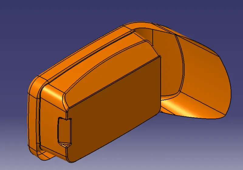
Create the Coin Holder Plastic component through the given Class-A surface. To begin with, the tooling axis for the given Class-A Surface should be created meeting the requirements of the draft angle and at the end perform the Draft analysis on the model.
Take the Thickness of the component to be 2.5 mm
Theory:
The Coin Holder is used in automobiles for storage of coin and other small items which needs to easily accessible for the passengers.
The Location of the holder might be in the Dashboard,side door trims and between the car seats.
The design should be in a such a way that the it should blend in with other components and interior and should not take more space.
Also, it should be comfortable for easy access.
This report explains the process of coin holder design which is created based on the A-surface input recieved.
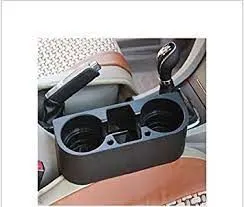
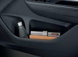
Images with different types & locations in the car:
Analysis:
Tooling axis:
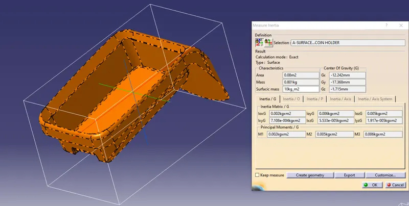
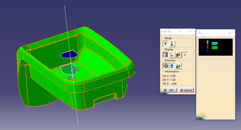
After analyzing the A-surface in three directions namely X,Y,Z directions it was determined that Y direction will be best for tooling axis as it was clearing all the surfaces and the notch.
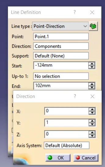
The measure Inertia tool was used to find the center of surface and non-associative point was created and based on that point a line was created in Y-direction.
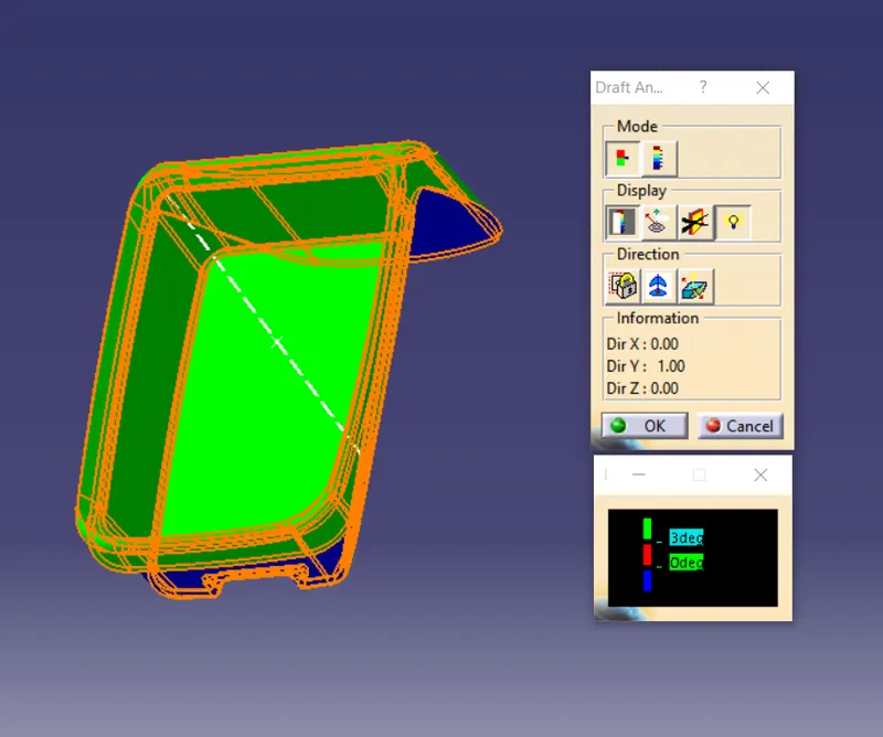
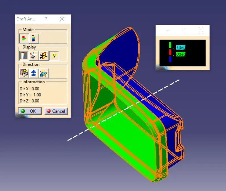
Then Using draft analysis ,it was checked if all the surface clears the draft angle of the 3 degrees where all the surfaces were clearing the draft angle.
The X,Y,Z values of the infromation were noted.
in the line's X,Y,Z direction, the Values of X,Y,Z were given by changing its directions from "Z-direction" to "Components" (See Image 4,5)
This line created acts as the tooling axis
B-surface Creation:
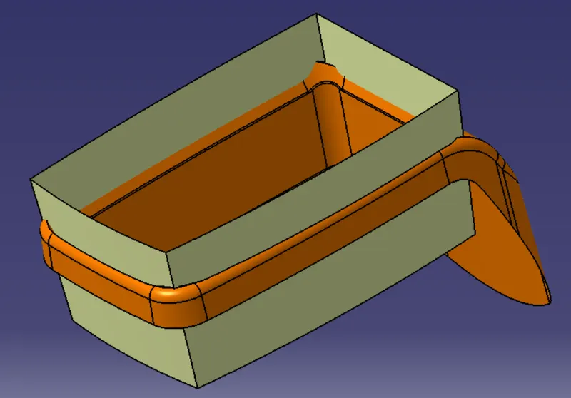
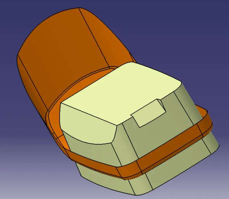
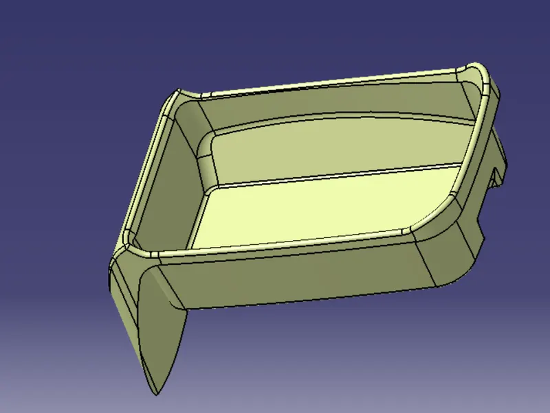
The next step was to create the B-surface. The A-surface without the radii were selected and extracted. These surfaces were untrimed.
These surfaces were then trimed together and offsetted to a thickness of 2.5 mm and the radii for the pocket were given. Thus the B-surface was created.

C-surface Creation:
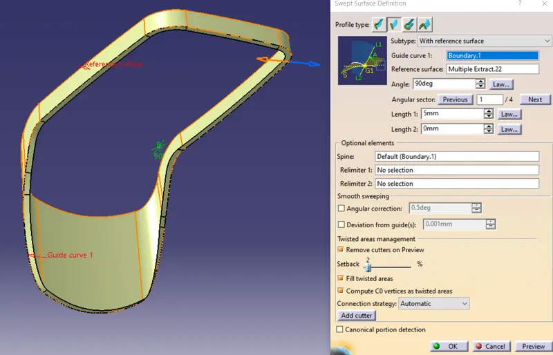
C-surfaces are created using the boundary of the A-surfaces and sweep with draft direction is used to create the required surface. The Boundary and an angle of 90 degree was given as input.
Final trim and closed Body:
All the three A,B and C surfaces were trimmed together to form a closed body. To check for any gap,
the body was selected for creating a boundary but error window showed up which meant it was closed body.(See Image 11,12)
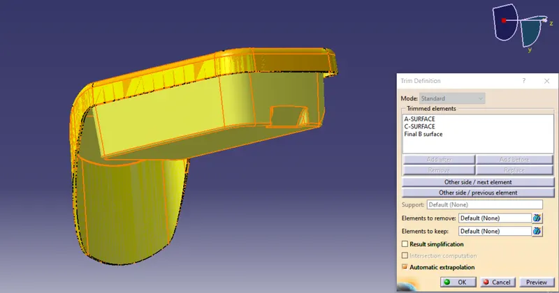
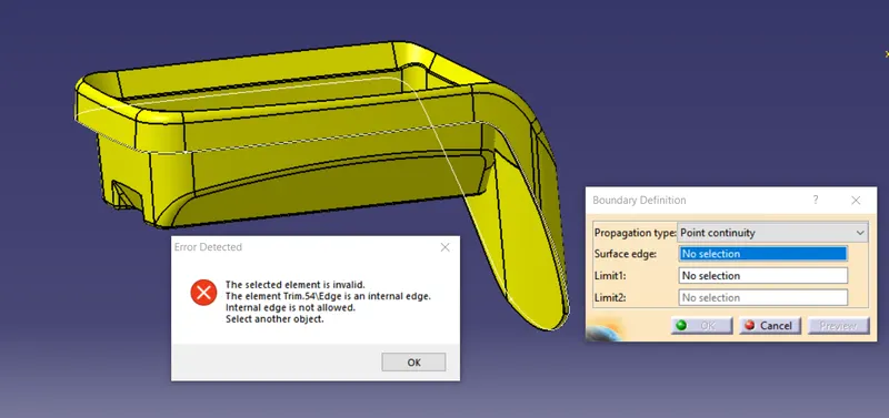
Images 11 and 12: Closed surface body
Solid Body:
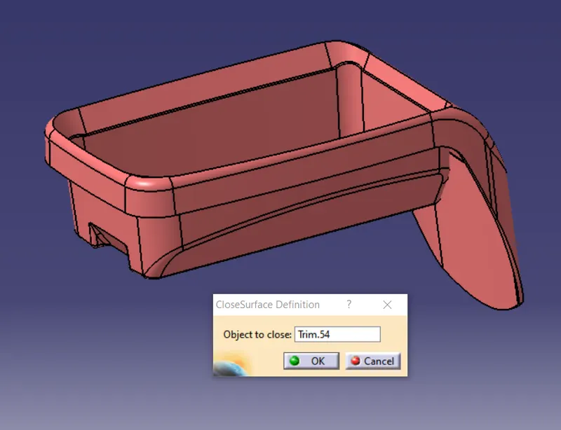
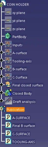
In part design workbench, A part body was inserted and using close surface option in surface related features, the solid body was formed by selectin the final trim. (See Image 13).
Draft analysis of component:
The below images showing the drafting analysis of component from different views.
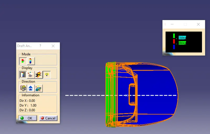
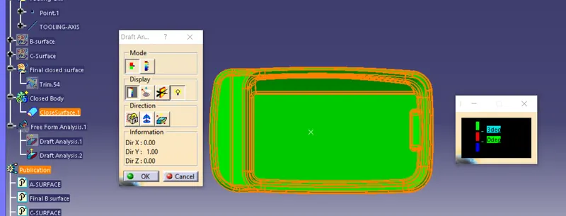
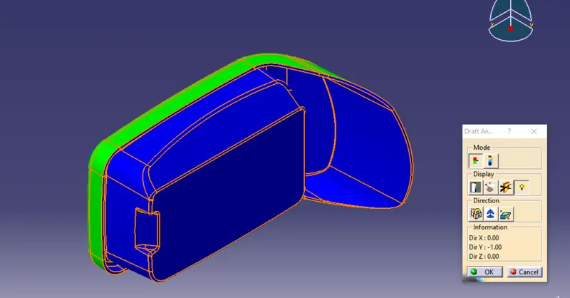
Hence the holder is created adequately with 2.5 mm thickness.