Week 9 - Attachment Feature Creation (Ribs & Screw Boss) - Challenge 1
AIM: Create the rib for the Centre console coin holder considering the design rules.
RIBS =
Ribs are thin wall-like structures that add support and rigidity to injection molded parts. They are thinner than primary walls and are used to support these walls, as well as bosses, by running perpendicular to these structures. Ribs are often used to replace thick wall sections to avoid sink marks, warp, and voids.
Ribs are a feature in plastic injection molded parts. They are thin extensions that run perpendicular from a wall or plane. They are commonly used to provide additional support and strength to a part. Thickness and location are essential to rib design.
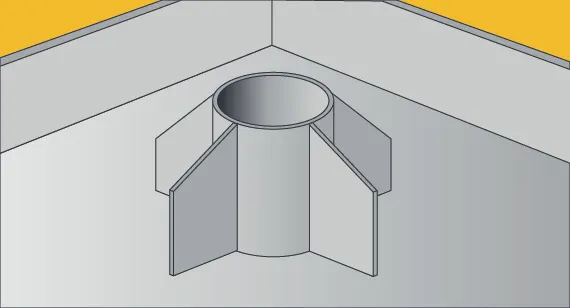
Ribs are used to strengthen the walls of your mould without increasing wall thickness which means that you minimise the problems that come into play when the wall thicknesses have to be increased. In essence, if the wall is too thick, warping and sinking can result so that the entire design may need to be rejected. Ribs & Bosses. Both ribs and bosses are functional features in many plastic part designs. Ribs offer stability to side walls and standoffs such as bosses.
The thickness of the rib should be approximately 50 to 60% of the general wall thickness of the part. Exceeding this value may lead to sink marks on the surface opposite the ribs.
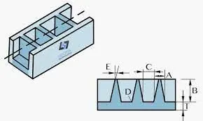
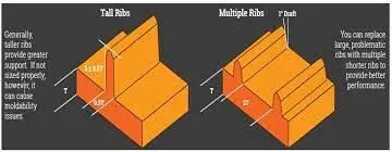
Both ribs and gussets provide stability in parts without having to increase wall thickness, and are particularly beneficial for parts with already thin walls that could potentially be compromised by end user wear and tear. It’s important to note that ribs and gussets should be no more than 60 percent of nominal wall thickness. These features are kept thinner than the primary walls in an effort to avoid overly thick sections where ribs and gussets intersect with the wall. When you have a surplus of material meeting at internal rib-to-wall intersections, sink marks can appear on the visible side of the part.
Product designers can play with different ribbed formations to create square, rectangle, diamond, triangle, or honeycomb patterns that stiffen the part. A pattern of ribs is equivalent to coring out unneeded material, leaving only the rib support system—it also reduces the weight and cost of the part. But, remember to not remove surfaces and features that interface with the other parts in the product assembly.
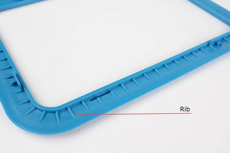
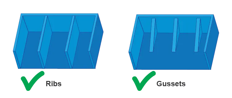
Ribs are indispensable functional structures on many plastic parts. It can effectively improve the rigidity and strength of plastic parts like the H beam. By using ribs, it is not necessary to greatly increase the wall thickness of the plastic parts, and ribs are not undercut structures like the H beam whose structure will be difficult to make for plastic injection molding. So ribs work well for plastic parts that are subject to pressure, torsion and bending. Ribs can also act as internal flow passages to aid in the plastic melt filling flow, which is of great help to the formation of complex and large plastic parts.
Ribs are generally designed on the non-appearing surface of the plastic part, and its direction is as close as possible to the flow direction of plastic melt filling. Ribs should neither be too long nor too thick, otherwise, it will increase the difficulty of injection molding, causing problems such as voids and sink marks on the back.
Regarding the ribs design, we need to talk about mainly 2 kinds of plastic materials, thermoplastic and thermosetting plastic.
Thermoplastic refers to a plastic that has heat softening and cooling hardening properties. Most of the plastics we use in our daily lives fall into this category. They can be recycled and reused, such as ABS, Acrylic, Nylon, PE, PP, PS, PC…
Thermosetting plastic refers to a plastic that cures when heated, it is insoluble and does not melt. They can only be formed once, such as Epoxy resin, Polyurethanes, Vulcanized rubber.
GUSSETS:
Gussets are a subset of ribs that are often used to support bosses, though they can support walls and other ribs as well
DESIGN RULES for RIBS:
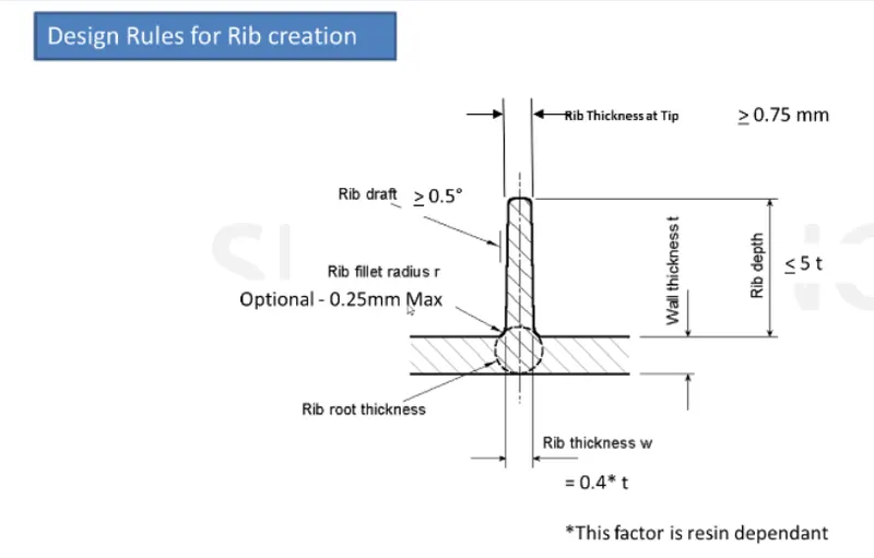
- Rib thickness - Ribs should be designed to be 40 percent of the nominal wall thickness. Thinner does not provide much structure and may be hard to fill. Thicker ribs are tempting, but they can begin to introduce sinks on the cosmetic surface.
- Rib height - The Rib height should be greater than or equal to 5 times the wall thickness.
- Rib spacing - Increase the number of ribs rather than their height to increase stiffness. Ribs should be spaced a minimum of two times the nominal wall thickness apart from one another. or it can be done in the ratio as well. The ratio will be of a height to width ratio.
- Minimum thickness at the tip - We have to ensure that the minimum thickness at the rib tip must be 0.75 mm
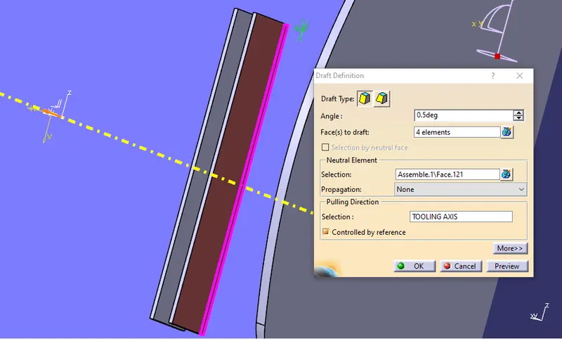
- Draft - A minimum 0.5-degree draft will ensure that they release from the tool during molding.
- Radii - The fillets provided in the ribs should be in the range of 0.25mm to 0.5mm. Generally, it is recommended to give 0.25mm fillets.
Given data:
t = 'Wall Thickness' = 2.5mm.
To calculate the following data using rib design rules
θ = ' Rib Draft' = 0.5°
r = 'Rib Fillet radius' = 0.25mm
tt = 'Rib Tip Thickness' = 0.75mm
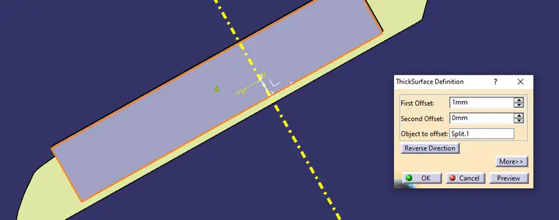
w = ' Rib Thickness ' = 0.4 * t = 0.4 * 2.5 = 1mm.
d = ' Rib Depth ' ≤ 5*t = 5*2.5 = 12.5mm.
MAIN TREE:
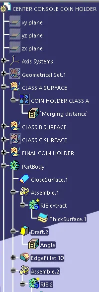
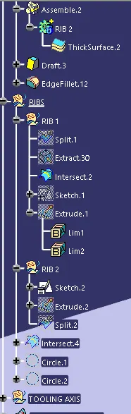
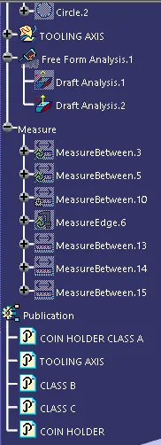
Create a Tooling Axis for the Class A surface.
TREE:
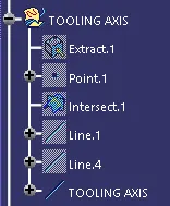
- Create a point on the class A surface to move the main tool for component creation on the base surface.
- Mask an axis over the point created with the same directions as the main axis
 .
. - Using Intersect command from Generative Shape design select the YZ plane as the first element and the class A surface as the second element
 .
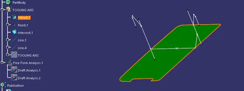
. - After creating the intersecting lines select the Line command and join the vertices which show the most possible draft angle manufacturable.
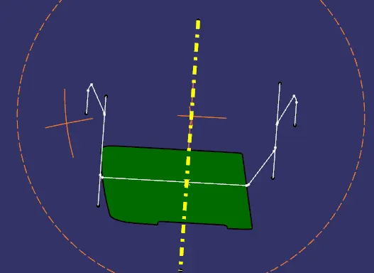
- Bisect those two lines over the axis point we created
 .
.
OBJECTIVE 2: DRAFT ANALYSIS of Class A surface:
Note: Class A surface was constructed wrongly as there is no draft angle on the bin walls of the coin holder.
PROCEDURE:
- After Tooling Axis Select the Feature Draft Analysis option from the Insert Option
 .
. - Select the element to analyze.
- Next click on Use the compass to define the new current draft direction option and make it align with the tooling axis by dragging it to the axis
 .
. - If the color appears blue just click the invert option on the right side of the draft direction axis button.
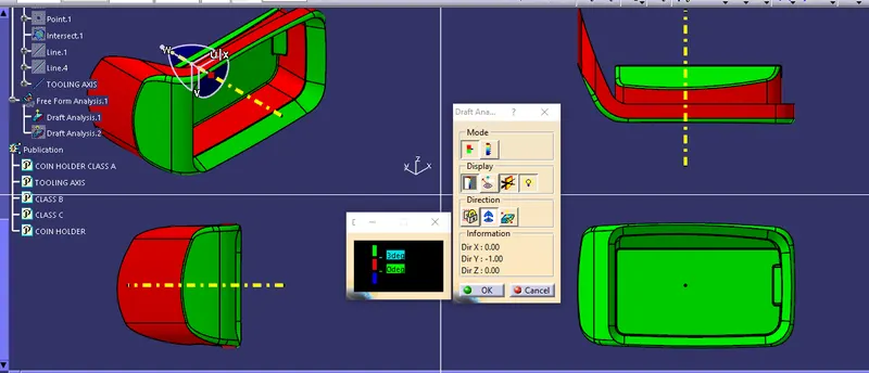
OBJECTIVE 3: Creating RIBS on the base of the Coin Holder.
TREE:
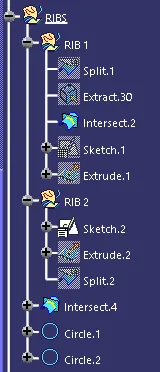
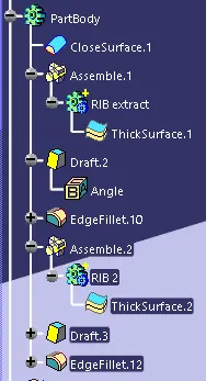
SKETCH:
Extract the base surface and create a sketch on it.
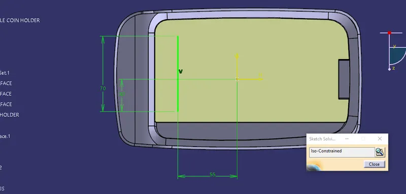
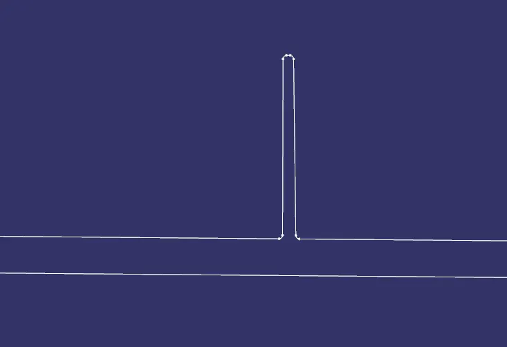
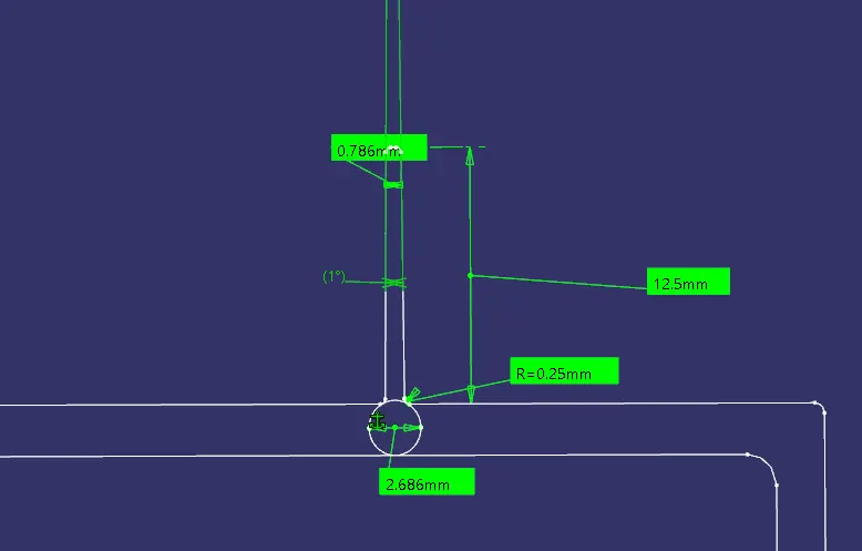
In Generative Shape Design, Extract the surface up to 12.5 mm as calculated.
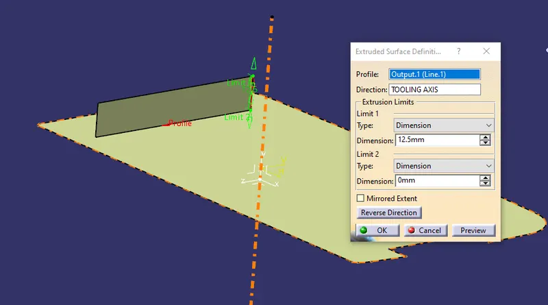
In part design, Give the thickness of the rib as per the calculations (1mm).
A draft angle of 0.5 is estimated.
Fillets of 0.25mm are given to all faces.
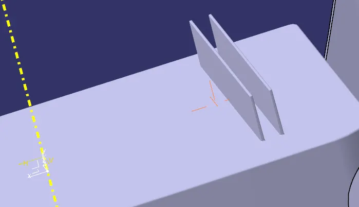
An Intersection showing the rib with its dimensions to see if it satisfied the design conditions.
SECOND RIB:
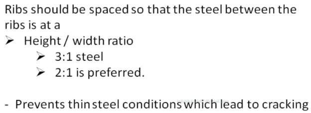
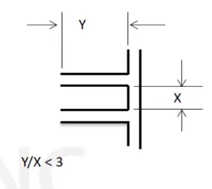
For the location of the second rib, we know the value of Y which is rib depth as 12.5 mm.
So gap 'X' should be Y/3
therefore, 12.5/3= 4.1667mm
but considering the thickness of ribs adding 1 mm to both sides, we get 4.1667+1=5.1667mm.
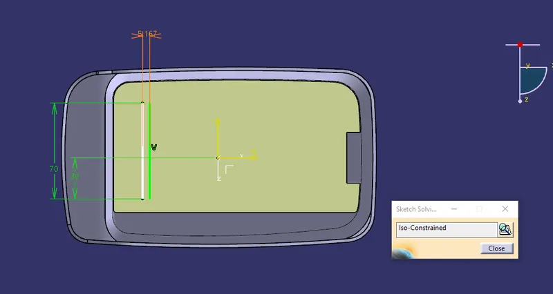
Similarly to the first rib do all the processes the same.
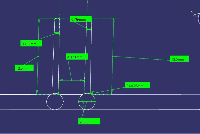
RIB root Thickness for both ribs is the same 2.686 mm which is almost equal to 2.5 m thickness and acceptable in manufacturing.
OBJECTIVE 4: Draft Analysis on Final component with ribs.
PROCEDURE:
- After Tooling Axis Select the Feature Draft Analysis option from the Insert Option.
- Select the element to analyze.
- Next click on Use the compass to define the new current draft direction option and make it align with the tooling axis by dragging it to the axis.
- If the color appears blue just click the invert option on the right side of the draft direction axis button.
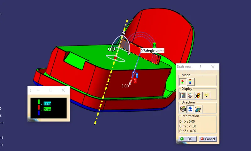
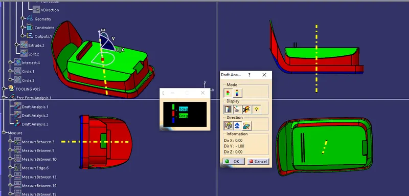
Hence the analysis is conducted successfully