Project 2 Thermal modeling of battery pack
Aim: To conduct Thermal Modelling of a 10 cell series assembly of a lithium ion battery model with one fault cell & compare thermal effects at various temperatures, charge & dischrge profiles.
Components used:
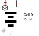
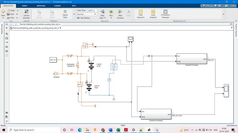
1. 9 cells in series
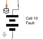
2. Fault cell
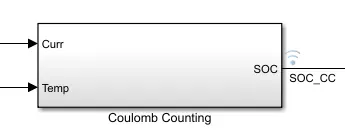
3. Coulomb Counting Block
4. AC Current Source

5. AC Current Sensor

6. Convective heat transfer block

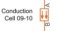
7. Conductive Heat Transfer Block
8. Temperature Source

9. Temperature Sensor

10. Temperature Reference

11. Electrical Reference

12. Solver Configuration
13. Scope

14. PS-Simulink Converter

Model 1:
Considering a battery of 65kWh with a current capacity of 200Ah & voltage of 325V.
We create a the model as follows
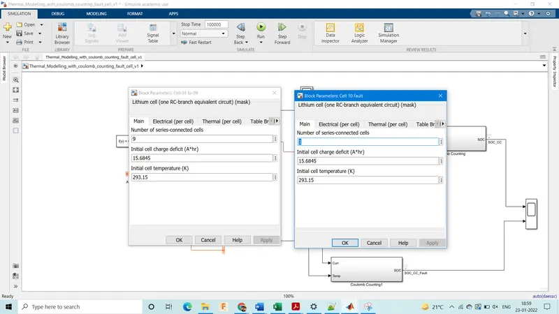
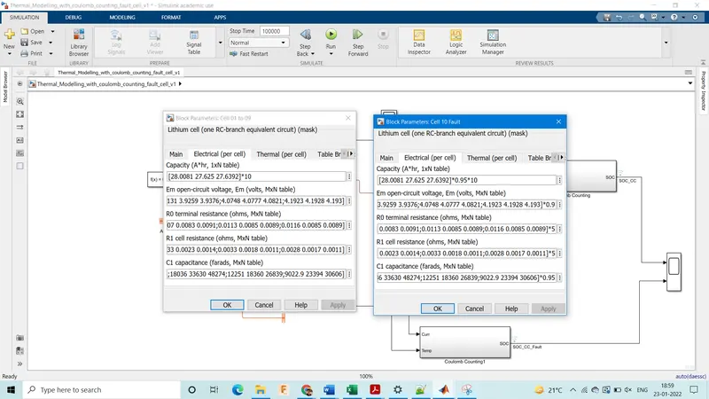
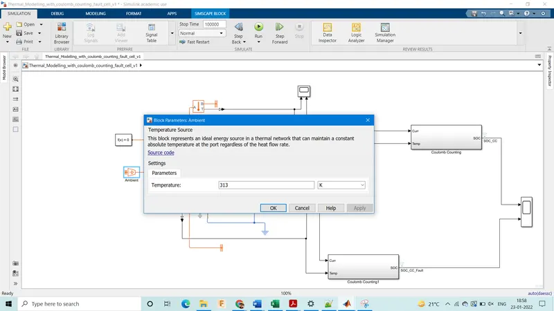
These are the required parameters:
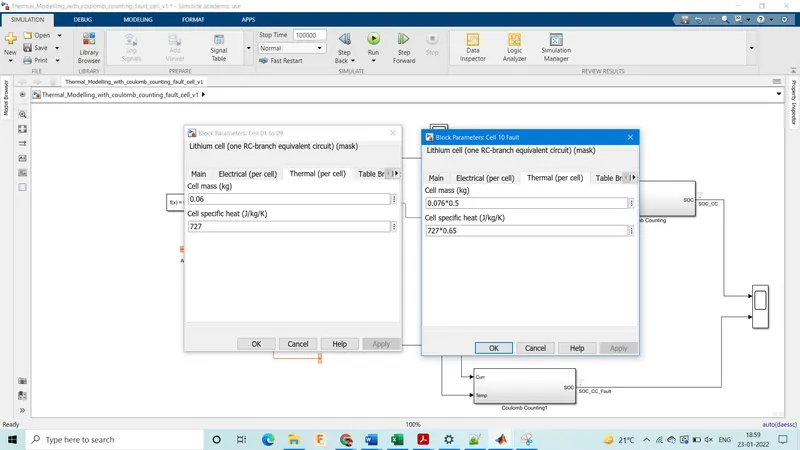
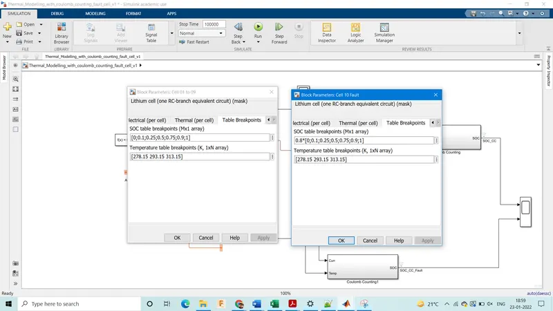
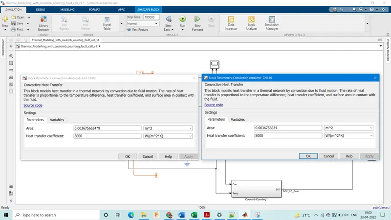
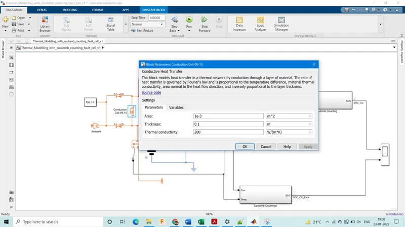
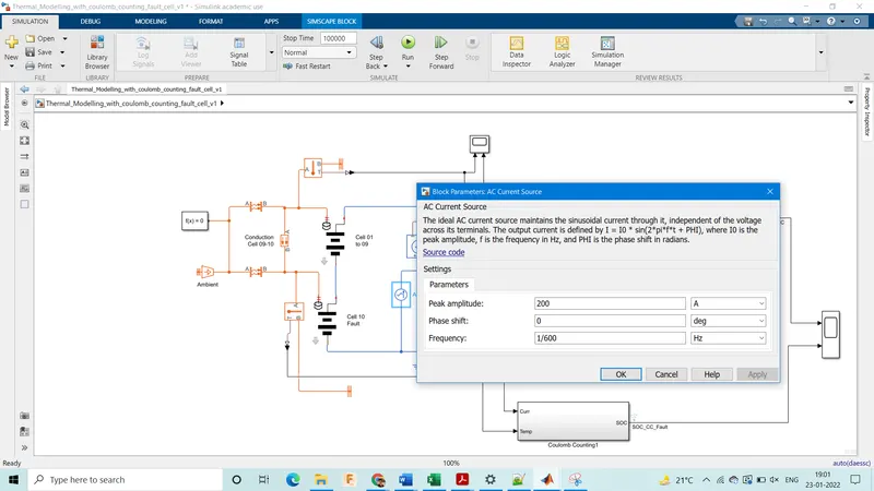
At Temperature 313K

We have designed the system for 333K i.e 60 deg Celcius as a normal cell is supposed to withstand that temperature & should not have thermal runaway upto 60 deg celcius(although cell temperature should be ideally 25 deg Celcius, but here we design only to avoid thermal runaway), Considering this condition we have kept the convetive heat transfer coefficient of 8000 W/K-m^2 which is for a liquid forced cooling system. With this cooling system, the temperature of each cell always remains lesser than 60 deg celcius & considering the ambient temperature will lower than 40 deg celcius in most cases this system could be used.
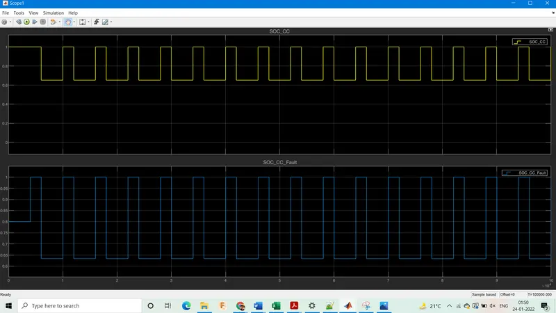
We obseve here that the fault cell would go upto 370 K & is in the a condition where it may undergo thermal runaway, this is due to the difference is mass & thermal capacity & electrical capacity of the fault cell. Also we can note that the SoC of the faulty cell is slightly lower than the SoC of the series cells (65%), this is due to the imbalance of the fault cell capacity.
At Temperature 308K
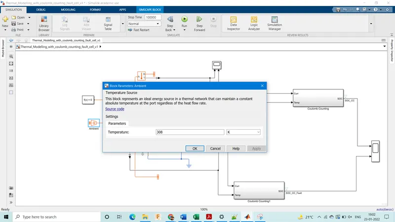


At 308 K the series cells discharge upto 65% while the fault cells discharges lower to about 62%. The temperature of the series cells is about 320K while that of fault cell is over 360K & it may undergo thermal runaway, this is due to the difference is mass & thermal capacity & electrical capacity of the fault cell. We can also observe that the average temperature both cell sets is lower for a lower ambient temperature is lower by about the same margin. This shows there is a linear relationship between the ambient temperature & cell temperatures.
At Temperature 303K
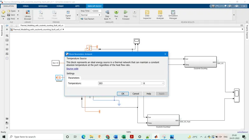
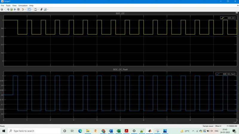

At 303 K the series cells discharge upto 65% while the fault cells discharges lower to about 62%. The temperature of the series cells is about 317K while that of fault cell is over 360K & it may undergo thermal runaway, this is due to the difference is mass & thermal capacity & electrical capacity of the fault cell.
Charge & Discharge changes:
Current=225A
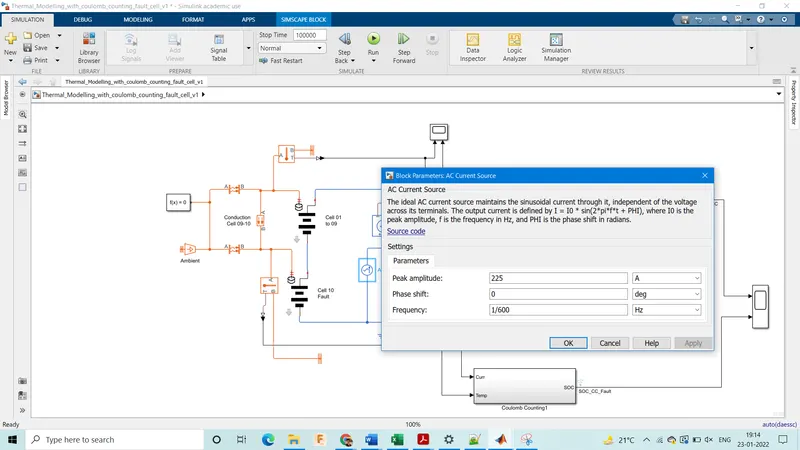
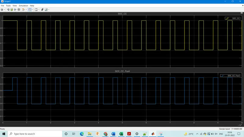

For a higher value of current(225A, compared to 200A) at 313K ambient we observe that the temperature increases from 325K to 330K. This shows that higher charge & discharge current increses the temperature of the battery.
Also we note that for higher current the battery experiences greater discharge. Here too, the fault cell discharges a little more than the series cells & is in a very high temperature zone at 385K, prone to thermal runaway.
Current= 250A
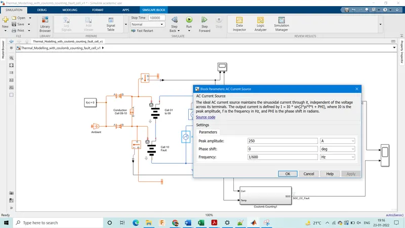
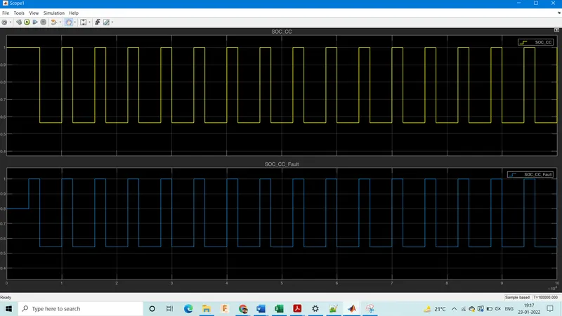

For a higher value of current(250A, compared to 200A) at 313K ambient we observe that the temperature increases from 325K to 334K. This shows that higher charge & discharge current increses the temperature of the battery.
Also we note that for higher current the battery experiences greater discharge. Here too, the fault cell discharges a little more than the series cells & is in a very high temperature zone at 400K, prone to thermal runaway. Here we also note that with increase in current value, the temperature of the fault cell increases exponentially faster than that of the series cells (series cells temperature changed by 4K while fault cell by 15K from previous case ie change from 225A to 250A).
Current=300A
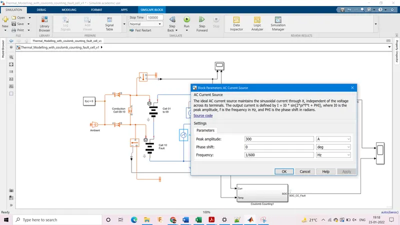
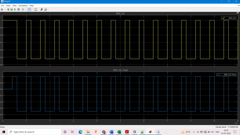

For a higher value of current(300A, compared to 200A) at 313K ambient we observe that the temperature increases from 325K to 343K. This shows that higher charge & discharge current increses the temperature of the battery.
Also we note that for higher current the battery experiences greater discharge. Here too, the fault cell discharges a little more than the series cells & is in a very high temperature zone at 440K, prone to thermal runaway. Here we also note that with increase in current value, the temperature of the fault cell increases exponentially faster than that of the series cells (series cells temperature changed by 9K while fault cell by 40K from previous case ie change from 250A to 300A).
Now at 300A itself we can change the frequency of the signal as well to 1/3600 Hz
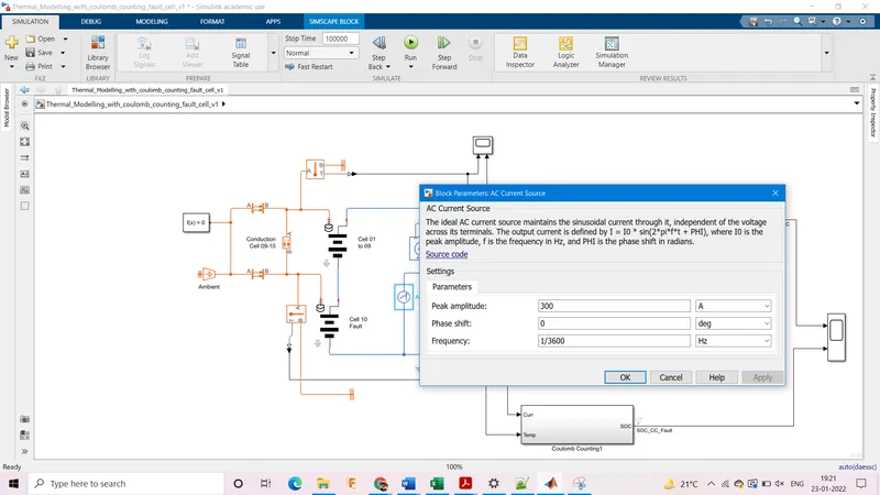
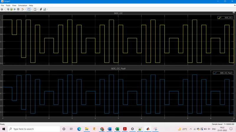
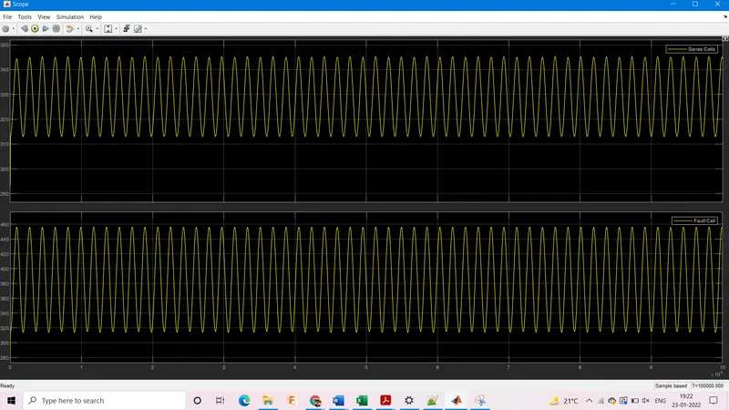
This changes the nature of the signal & that of charge discharge as well. The discharge of the fault cell is still higher than the series cells.
Cooling Systems:
While advancements have been made in electric vehicle batteries that allow them to deliver more power and require less frequent charges, one of the biggest challenges that remain for battery safety is the ability to design an effective cooling system.
In electric cars, discharging the battery generates heat; the more rapidly you discharge a battery, the more heat it generates.
Batteries work based on the principle of a voltage differential, and at high temperatures, the electrons inside become excited which decreases the difference in voltage between the two sides of the battery. Because batteries are only manufactured to work between certain temperature extremes, they will stop working if there is no cooling system to keep it in a working range. Cooling systems need to be able to keep the battery pack in the temperature range of about 20-40 degrees Celsius, as well as keep the temperature difference within the battery pack to a minimum (no more than 5 degrees Celsius).
If there is a large internal temperature difference, it can lead to different charge and discharge rates for each cell and deteriorate the battery pack performance.
Potential thermal stability issues, such as capacity degradation, thermal runaway, and fire explosion, could occur if the battery overheats or if there is non-uniform temperature distribution in the battery pack. In the face of life-threatening safety issues, innovation is continually happening in the electric vehicle industry to improve the battery cooling system.
There are two ways of cooling: Passive & Active
Passive means that battery is allowed to cool in ambient temperature without spending any energy in the process through natural convetion.
While active cooling spends some energy in the process by use of fans, phase change materials, pumping liquid coolants etc
-
Phase change material absorbs heat energy by changing state from solid to liquid. While changing phase, the material can absorb large amounts of heat with little change in temperature. Phase change material cooling systems can meet the cooling requirements of the battery pack, however, the volume change that occurs during a phase change restricts its application. Also, phase change material can only absorb heat generated, not transfer it away, which means that it won’t be able to reduce overall temperature as well as other systems. Although not favorable for use in vehicles, phase change materials can be useful for improving thermal performance in buildings by reducing internal temperature fluctuations and reducing peak cooling loads.
-
Cooling fins increase surface area to increase the rate of heat transfer. Heat is transferred from the battery pack to the fin through conduction, and from the fin to the air through convection. Fins have high thermal conductivity and can achieve cooling goals, but they add a lot of additional weight to the pack. The use of fins has found a lot of success in electronics, and traditionally they have been used as an additional cooling system on internal combustion engine vehicles. Using fins to cool the electric car battery has fallen out of favor since the additional weight of the fins outweighs the cooling benefits.
-
Air cooling uses the principle of convection to transfer heat away from the battery pack. As air runs over the surface, it will carry away the heat emitted by the pack. Air cooling is simple and easy, but not very efficient and relatively crude compared to liquid cooling. Air cooling is used in earlier versions of electric cars, such as the Nissan Leaf. As electric cars are now being used more commonly, safety issues have arisen with purely air-cooled battery packs, particularly in hot climates. Other car manufacturers, such as Tesla, insist that liquid cooling is the safest method.
-
Liquid coolants have higher heat conductivity and heat capacity (ability to store heat in the form of energy in its bonds) than air, and therefore performs very effectively and own advantages like compact structure and ease of arrangement. Out of these options, liquid coolants will deliver the best performance for maintaining a battery pack in the correct temperature range and uniformity. Liquid cooling systems have their own share of safety issues related to leaking and disposal, as glycol can be dangerous for the environment if handled improperly. These systems are currently used by Tesla, Jaguar, and BMW, to name a few.
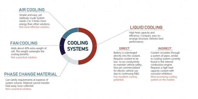
A research group from the National Renewable Energy Lab (USA) and the National Active Distribution Network Technology Research Center (China) compared four different cooling methods for Li-ion pouch cells: air, indirect liquid, direct liquid, and fin cooling systems. The results show that an air-cooling system needs 2 to 3 times more energy than other methods to keep the same average temperature; an indirect liquid cooling system has the lowest maximum temperature rise; and a fin cooling system adds about 40% extra weight of cell, which weighs most when the four kinds cooling methods have the same volume. Indirect liquid cooling is a more practical form than direct liquid cooling though it has slightly lower cooling performance.
The determining features of an electric vehicle battery cooling system are temperature range and uniformity, energy efficiency, size, weight, and ease of usage (i.e. implementation, maintenance).
Each of these proposed systems can be designed to achieve the correct temperature range and uniformity. Energy efficiency is more difficult to achieve, as the cooling effects need to be greater than the heat generated when powering the cooling system. Also, a system with too much additional weight will drain energy from the car as it outputs power.
Phase change material, fan cooling, and air cooling all fail at the energy efficiency and size and weight requirements, though they may be just as easy to implement and maintain as liquid cooling. Liquid cooling is the only remaining option that does not consume too much parasitic power, delivers cooling requirements, and fits compactly and easily into the battery pack. Tesla, BMW i-3 and i-8, Chevy Volt, Ford Focus, Jaguar i-Pace, and LG Chem’s lithium-ion batteries all use some form of liquid cooling system. Since electric vehicles are still a relatively new technology, there have been problems maintaining temperature range and uniformity in extreme temperatures even when using a liquid cooling system. These are likely due to manufacturing problems, and as companies gain experience developing these systems, the thermal management issues should be resolved.
In liquid cooling systems, there is another division between direct and indirect cooling—whether the cells are submerged in the liquid or if the liquid is pumped through pipes.
-
Direct cooling systems place the battery cells in direct contact with the coolant liquid. These thermal management schemes are currently in the research and development stage, with no cars on the market using this system. Direct cooling is more difficult to achieve, due to the fact that a new type of coolant is required. Because the battery is in contact with the liquid, the coolant needs to have low to no conductivity.
-
Indirect cooling systems are similar to ICE cooling systems in that both circulate liquid coolant through a series of metal pipes. However, the construction of the cooling system will look much different in electric vehicles. The structure of the cooling system that achieves maximum temperature uniformity is dependent on the shape of the battery pack and will look different for each car manufacturer.
Making coolants safe and effective
Given that liquid cooling is the most efficient and practical method of cooling battery packs, and currently the most widely used, attention needs to be given to the type of coolant used in these systems.
Indirect Liquid Cooling
The indirect liquid cooling systems for electric vehicles and the conventional internal combustion engine (ICE) cooling system are very similar: both circulate coolant throughout a series of metal pipes to transfer heat away from the battery pack or engine. Therefore, coolant requirements for indirect liquid cooling systems will be very similar to traditional ICE coolants.
99% of the coolant is a commodity such as glycol or polyglycol, but the 1% additive package is what separates good from great engine protection and performance. When circulating a liquid coolant throughout metal piping, it is important to protect against corrosion to protect vehicle safety and performance.
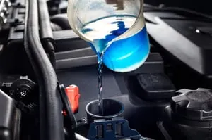
Metal is very unstable, so it naturally wants to react with other elements by losing electrons to move to a more stable state. Corrosion happens because impurities in the coolant liquid have a positive charge on them, so they interact with the metal pipes and strip away some of the surface. Additive packages can be blended with antifreeze to form a coolant that protects against rust, scale, and corrosion. The additive packages used in ICE vehicles contain corrosion inhibitors to protect the many types of metals found in cooling systems, such as pipes, gaskets, connections, radiator, etc. The American Society for Testing and Materials maintains standards that coolants must meet for protection against corrosion of different metal types. What is currently known about corrosion prevention in internal combustion engine cooling systems can be easily applied to the indirect liquid cooling system in electric vehicles.
Direct Liquid Cooling
There are different coolant requirements for direct liquid cooling systems. In systems where the battery will be directly exposed to the coolant, such as with Fuel Cell Vehicles or direct liquid cooling, the coolant needs to be a low to no conductivity fluid. This is going to be very different from conventional ICE coolants that have a high conductivity. The reason for needing low/no conductivity is due to safety: electrons are flowing throughout the battery, and if they are exposed to a high conductivity fluid, this will lead to failure and explosion. Some examples of ways to keep coolant conductivity low are using deionized water as a medium for the fluid or having a non-salt-based fluid medium. These low & no-conductivity coolants are in the early stages of research and development.
Hence Thermal Modelling for a battery pack of 10 cells with one fault cell was done for different charge, discharge rates & different temperatures.
Reference: https://in.mathworks.com/help/physmod/simscape/ug/lithium-ion-battery-pack-with-fault.html