Week 8 - Challenge 6 - Core & Cavity Design
Aim:
Create the Core and cavity blocks for the switch bezel designed in the earlier challenge.
Theory:
The core & cavity are the shaped sections in either half of the mould tool which give the plastic product its final shape. The hot molten material is injected into the core & cavity and then sets hard into shape. The design of the core & cavity is essential in the correct formation of the product.
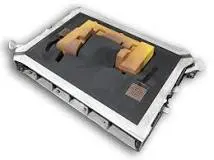
The cavity and core are used in pairs, with the cavity also referred to as the female mold and the core as the male mold.
These two mold components are the most important parts of a mold.
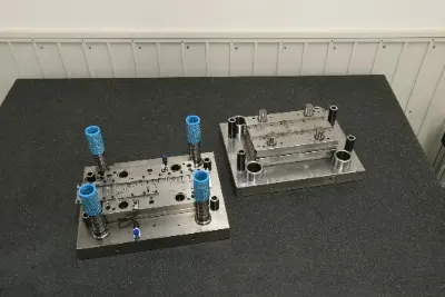
The parting surface of a mould are those surfaces of both mould plates adjacent to the impressions which butt together to form a seal and prevent the loss of plastic material from the impression. A parting line, in industrial casting of molds, is the border line in which draft angles change direction. One can check the parting line in the mould or product which divides the two half, i.e; the core and the cavity of a molded part. It is sometimes a starting point for the mold parting surface. In engineering drawing, a parting line is often abbreviated as PL. ASME's Y14.8 standard specifies a symbol for parting line. Engineering applications (seals, tight running molded parts) that require precision for shape control, call for removal of flashes. Many molders will repair or even replace the mold tooling so that the flash is reduced to an acceptable tolerance or eliminated altogether. Secondary operations to remove parting line flash include hand trimming, vibratory tumbling, media blasting and cryogenic deflashing.
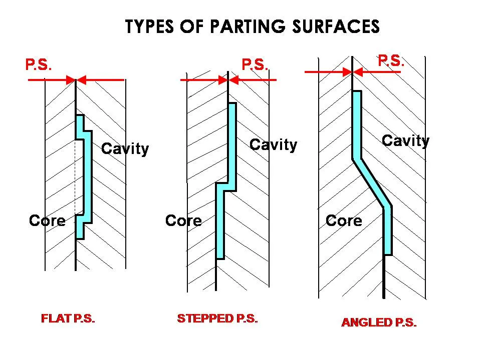
Design parting surface should follow the following principles:
- Design the injection mold structure as simple as possible. Avoid or reduce side parting as much as
possible to reduce the complexity of mold making. - Ease of de-molding. As far as possible, for instance, the plastic parts should stay in fixed halve of the
injection mold and ejected by ejection system, avoid side de-molding action. - Ensure the dimensional accuracy of the molded parts. Try to make the parts with similar
dimensional accuracy requirements in the same module to reduce manufacturing and assembly
errors. - Ensure appearance requirement of the molded parts. Flash or mismatch occurs usually on parting
surface, so the parting surface should not be designed on any high quality requirement surfaces. - Ensure adequate venting. If possible, parting surface should be place at the end of the mold flow.
Parting line:
A parting line, in industrial casting of molds, is the border line in which draft angles change direction. That is, it is the dividing line that splits the core and cavity halves of a molded part. It is sometimes a starting point for the mold parting surface.
Parting lines on injection-molded parts are a popular topic for product designers. Accordingly, this tip covers the types of parting lines you may encounter on plastic and liquid silicone rubber molded parts, and how you can properly address them.
When you are developing a 3D CAD model to be molded, you may not spend much time thinking about where its parting line will be, but it's worth noting because the location can affect your part in several ways. On some parts, the location for the parting line is obviously right down the middle, while on more complex parts, it may not be as obvious.
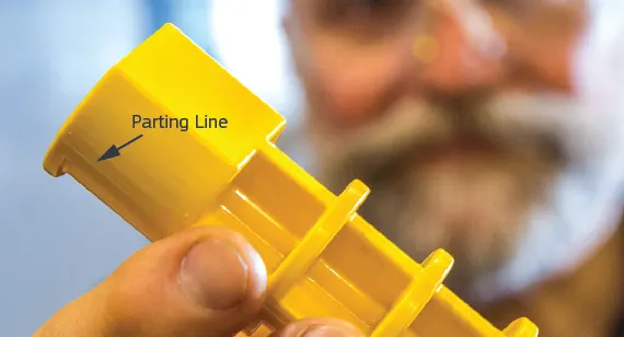
Take, for example, a simple plastic cup. The outer face is formed by one mold half (A-side), while the cup's inner surface and brim will be formed by the other mold half (B-side). The parting line occurs along the outside edge of the brim of the cup. For other designs, parting lines vary with geometry. A molded yellow flower, which was used as an art piece for children, depicts a parting line along its outer petals (see Figure 1).
Complex Shapes Present Challenges
When a design is a complex shape, determining where the parting line will be located can be more complicated. You can assume that if you send an undrafted 3D CAD model of such a part, Protolabs will determine where the parting line should be. However, in designing such a part, you might want to think about the parting line for one simple reason: Designers and molders look at parts differently. Molders share your interest in producing the best possible part, but the focus is on molding it correctly, whereas designers focus on how it will function after it comes out of the mold. The location of the parting line can affect both.
First of all, the location of the parting line determines the direction of mold opening and, consequently, the direction in which features must be drafted for easy ejection. Second, it affects where any vestiges left by the mating surfaces of the mold halves will be, and potentially, how those vestiges will look. Third, parting line location can also impact the cost of mold making and the type and cost of secondary operations needed to finish the part.
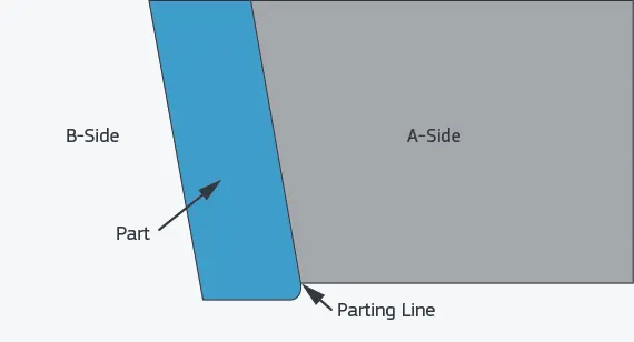
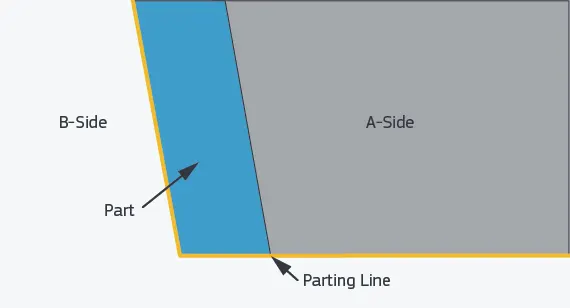
The plastic toy soldier is an obvious example of a design with a challenging parting line, but the issue can come up on simpler parts as well. For example, a straightforward geometric design with radiused or rounded edges can also be problematic. The parting line has to trace the path along which a tangent to the surface is parallel to the direction of mold opening. In Figure 2, the parting line has been placed across an otherwise smooth surface. Any mismatch in mold edges will create a fairly obvious seam, so a parting line in this location would create a need for tighter tolerances and potentially increase milling costs. The increased likelihood of flash could also impact both the cosmetics and functionality of the part, potentially making assembly of finished parts more difficult. If the parting line is instead placed along a sharp edge, the seam would be camouflaged, and the undesired manufacturing, functionality, and cosmetics issues outlined above (see Figure 3) would be avoided.
Liquid Silicone Rubber Parts
Designing parts for liquid silicone rubber (LSR) molding is similar to thermoplastic molding, though with the LSR processes, additional preparation to prevent flash should be considered. LSR flows into the mold as a liquid and will fill into gaps as small as 0.0002 in., which can result in flash. Though parting lines on LSR parts are likely less visible, and less intrusive, they are harder to prevent. You should also make sure that parting lines on LSR are not on a sealing surface. Simplifying and minimizing parting lines on LSR parts will help you get cleaner parts as quickly as possible.
Being Aware of Parting Lines
With all injection-molded parts, there are several ways to address parting line challenges. An awareness of the significance of the parting line is a good start. As stated earlier, parting line location is obvious and not a problem on many parts. For more complex parts, you may be able to use tools within some CAD packages to locate and evaluate split lines, or you can just upload a 3D CAD model online and we'll propose a parting line and suggest appropriate draft based on that orientation. Our software may also point out that the part cannot be made in a straight-pull mold and that design changes, side-actions, and/or pickouts may be required.
Advantages of parting line:
The parting line of a casting needs to be determined early in the design processes. When determining the location of the parting line the part designer and die cast engineer should work together to consider part functionality and die casting process. Often times it is useful to have most of the geometry in the ejector half; as this prevents the casting from sticking in the cover half.
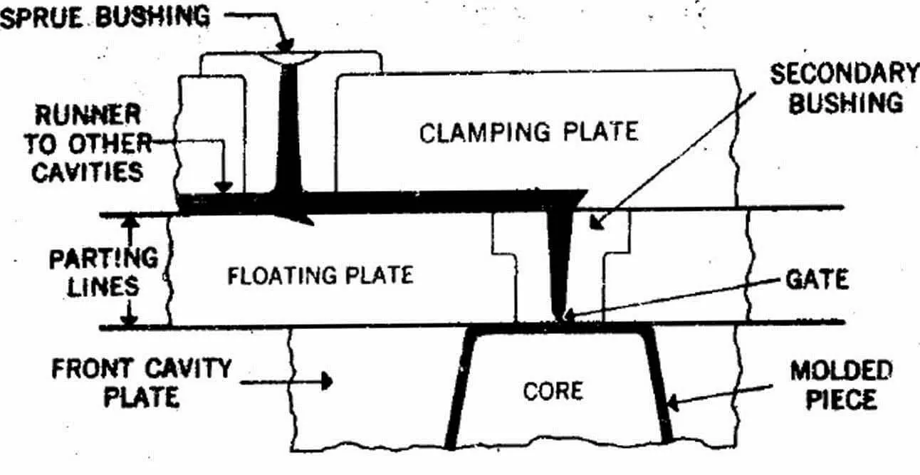
The parting line is created where the two halves of the die meet. Gates, overflows, and vents will connect to the casting at the parting line. Also, flash will form at the parting line when the pressure from the injected metal tries to force the die halves apart. During the trimming process the gates, overflows, vents, and flash will need to be removed by the trim die. A well designed parting line will ease the trimming process.
When flash occurs it increases the thickness of the parting line; altering dimensions measured across the parting line. For critical dimension it is important to have measurements in only one die half to reduce dimensional tolerance.
The parting line can also effect the life of the die. Metal injected straight onto a surface will erode that surface faster. Positioning of the parting line to allow metal to flow more smoothly will improve die life and casting quality. Cosmetic surfaces are typically placed on the cover side of the casting.
Analysis:
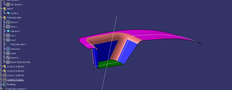
MAIN TREE:
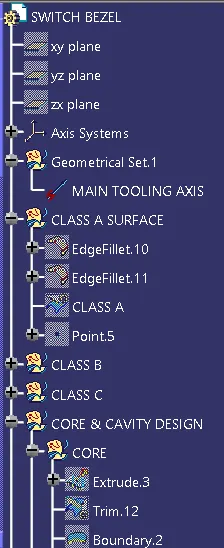
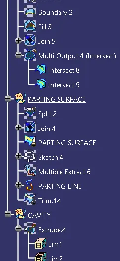
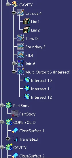
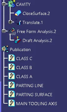
OBJECTIVE 1: Create a Tooling Axis for the Class A surface. (NOTE: Tooling Axis was already created)
TREE:
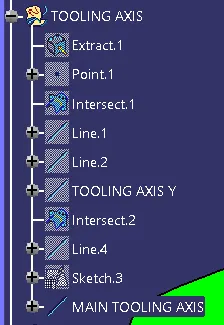
Procedure:
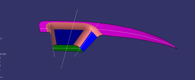
- Create a point on class A surface with the aim to move the main tool for component creation on the base surface.
- Mask an axis over the point created with the same directions as the main axis
 .
. - Using Intersect command from Generative Shape design select the YZ plane as the first element and the class A surface as the second element
 .
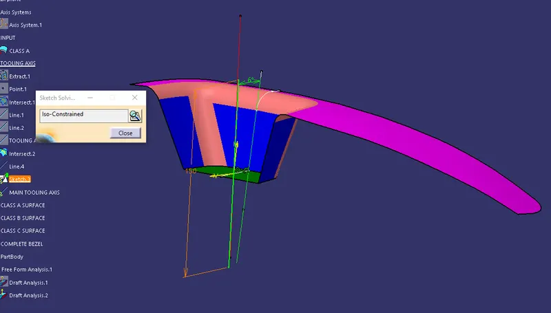
. - After creating the intersecting lines select the Line command and join the vertices which show the most possible draft angle manufacturable.
- Similarly, select the second axis and create intersecting lines but since only one side is available create a sketch of a line for the intersecting surfaces and make the draft line at an angle of 3 degrees.
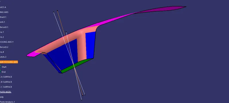
- Bisect those two lines over the axis point we created
 .
.
Using bisect command
Objective 2: DRAFT ANALYSIS of Solid Switch bezel.
Procedure:
- After Tooling Axis Select the Feature Draft Analysis option from the Insert Option
 .
. - Select the element to analyze.
- Next click on Use the compass to define the new current draft direction option and make it align with the tooling axis by dragging it to the axis
 .
. - If the color appears blue just click the invert option on the right side of the draft direction axis button.
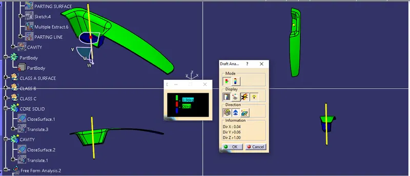
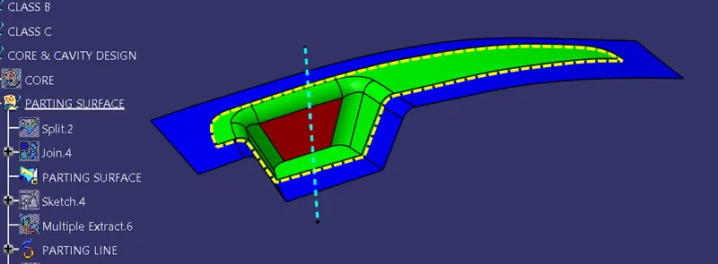
OBJECTIVE 3: Create Parting surface and line.
TREE:
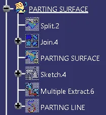
Procedure:
Of the class B Surface use the before offset command surface as extrapolated Class A surface.
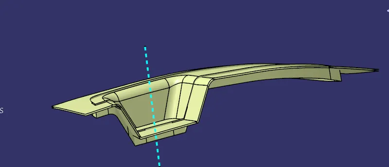
Trim the class A, B, and C to get the resulting surface.
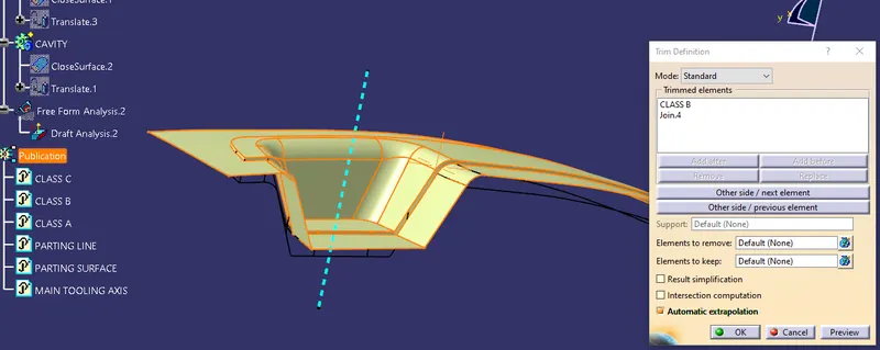
using Intersecting command intersect the class A and C surfaces to get the surface boundary for both the Classes.
OBJECTIVE 4: Creating Core and Cavity components:
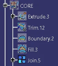
TREE:
Procedure:
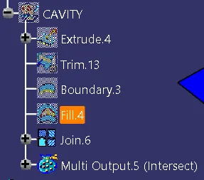
Create a Sketch of a rectangle just outside the parting line near inside the parting surface.
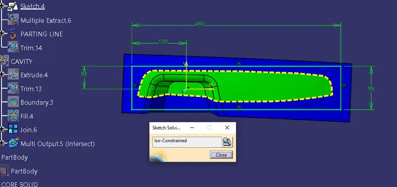
Extrude the sketch to the mirrored extent to clear some height over the surface intended in the direction of the tooling axis.
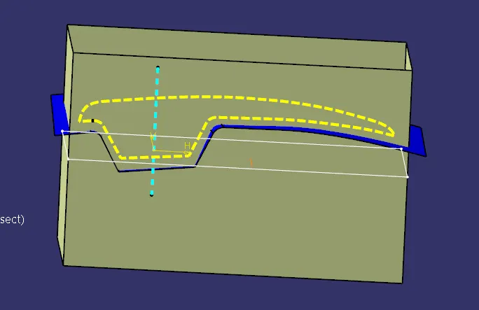
Trim with the parting surface.
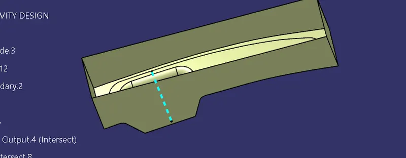
Create a boundary and fill the top area.
To create a closed surface go to the part workbench and use the Closed surface command to create a new body.
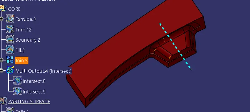
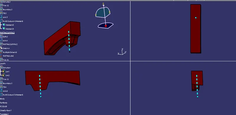
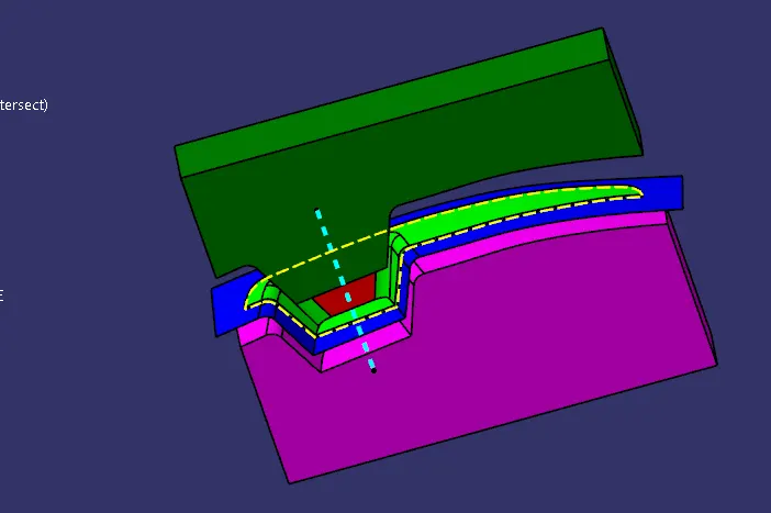
To understand more clearly here is an intersection of the YZ plane of the axis along the tooling axis created in both the core and parting surface.
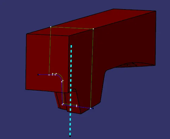
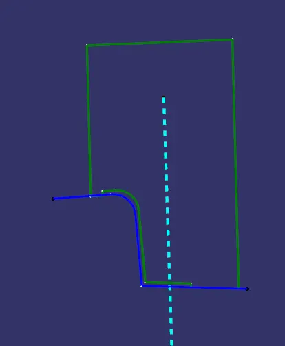
Similarly do for the Cavity of the part, instead of trim with parting surface use Class B surface.
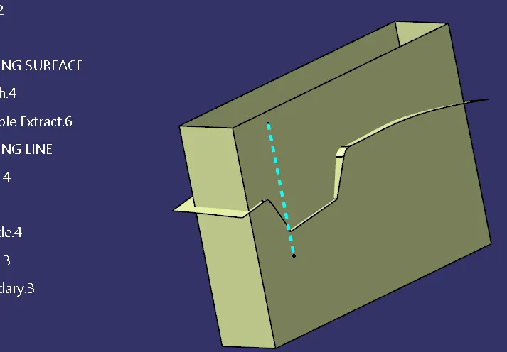
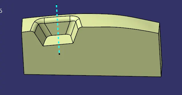
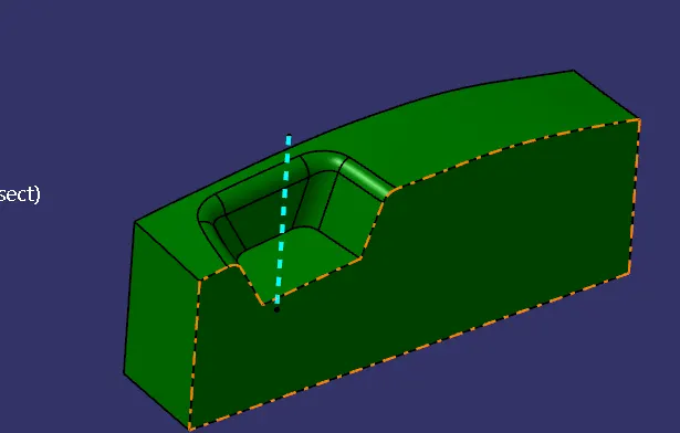
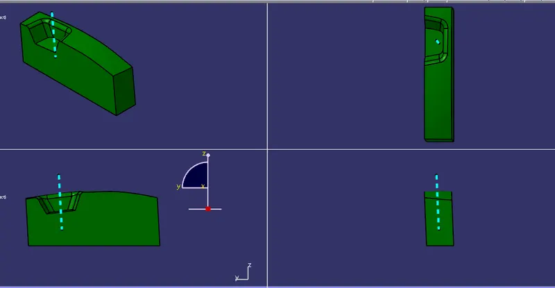
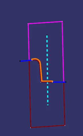
Intersection of both core and cavity with parting surface is as follows
Closed surface of both core and cavity with translation.
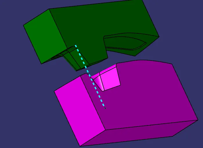
Component parting surface and parting line with core cavity.
Hence the analysis is conducted successfully.