Week 8 - Challenge 1 - Base Bracket Design
Theory:
The clinical importance of bracket base morphology is twofold. The first is related to the fact that the longevity and integrity of the adhesive bond to enamel depend strongly on the base characteristics. The second is associated with the effect of base characteristics on enamel damage after debonding of the ceramic brackets, as previously described. In general, the bonding mechanisms that have been implemented by manufacturers are classified into three major categories:
- 1.mechanical retention employing undercuts and grooves that provide interlocking;
- 2.chemical coating which enhances bond strength by chemical bonding with the adhesive resin; and
- 3.micromechanical retention using surface features in the micron size range, such as spherical particles, protruding crystals, and grooves, to increase retention with resin.
Examples of the first manufacturer strategy are illustrated in. The base morphology utilizes large recesses such as grooves and undercuts, to provide mechanical bonding to the adhesive resin. In some commercial products, this surface pattern is combined with the presence of a silane layer to increase further the bond strength with enamel.
The second strategy employs brackets with a smooth base surface where the bonding with adhesive resin relies on a chemical coating. A silane layer is applied on the surface and used as a coupling agent between the inert alumina and the adhesive resin to promote chemical adhesion. It has been previously reported that this technology provided even higher bond strength compared to mechanical retention.
The third category uses a rough base to provide micromechanical retention to the adhesive resin. The surface consists of spherical particles, or sharp-edged randomly oriented crystals. This type of micromechanical bonding does not appear to provide sites of problematic local stress concentrations, thus developing a more homogeneous shear stress distribution over the entire underlying adhesive resin.
Analysis:
GIVEN CLASS A SURFACE:
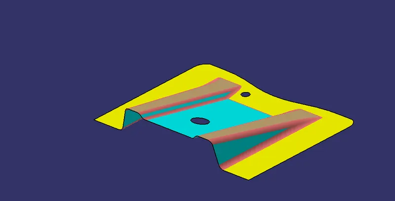
TREE STRUCTURE for creating Tool AXIS:
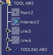
PROCEDURE:
A) TOOLING AXIS CREATION:
- Create a point on class A surface with the aim to move the main tool for component creation.
- Mask an axis over the point created with the same directions as the main axis
 .
. - Using Intersect command from Generative Shape design select the YZ plane as the first element and the class A surface as the second element
 .
. - After creating the intersecting lines select the Line command and join the vertices which show the most possible draft angle manufacturable and bisect those two lines over the axis point we selected at the first
 .
.
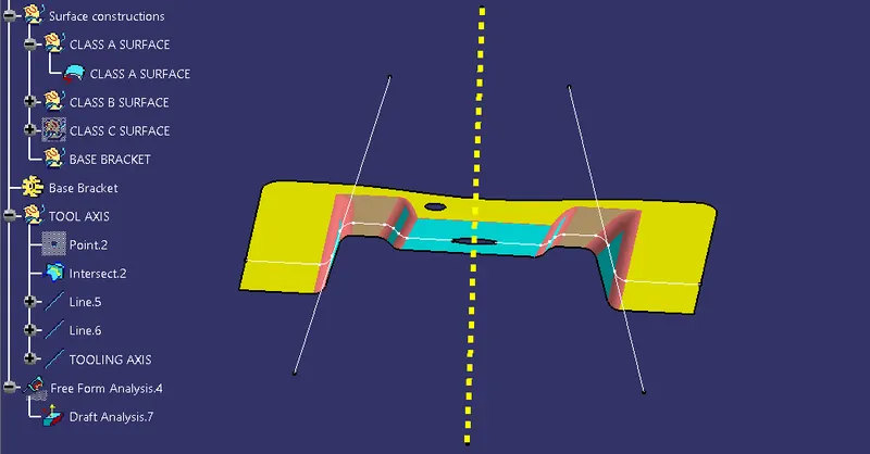
- This is the tooling axis for the part we need to manufacture.
TREE STRUCTURE For Draft analysis:

PROCEDURE for Draft Analysis of Class A Surface:
- After Tooling Axis Select the Feature Draft Analysis option from the Insert Option
 .
. - Select the element to analyze.
- Next click on Use the compass to define the new current draft direction option and make it align with the tooling axis by dragging it to the axis
 .
.
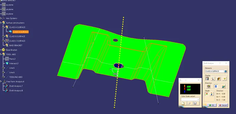
- If the color appears blue just click the invert option on the right side of the draft direction axis button.
TREE STRUCTURE for creating Class B surface.
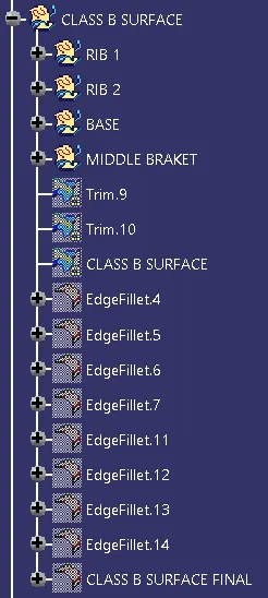
RIB 1&2, BASE, and MIDDLE BRACKET:
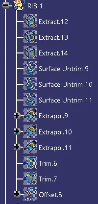
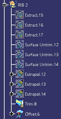
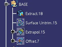
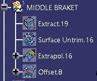
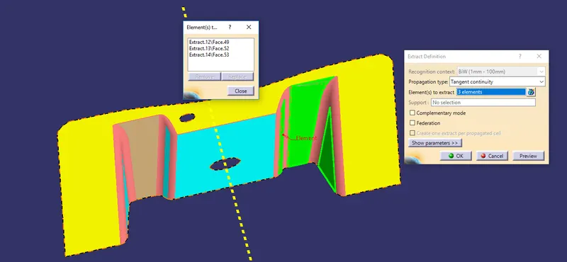
Using the Extract option select the first set of ribs from the Class A surface .
.
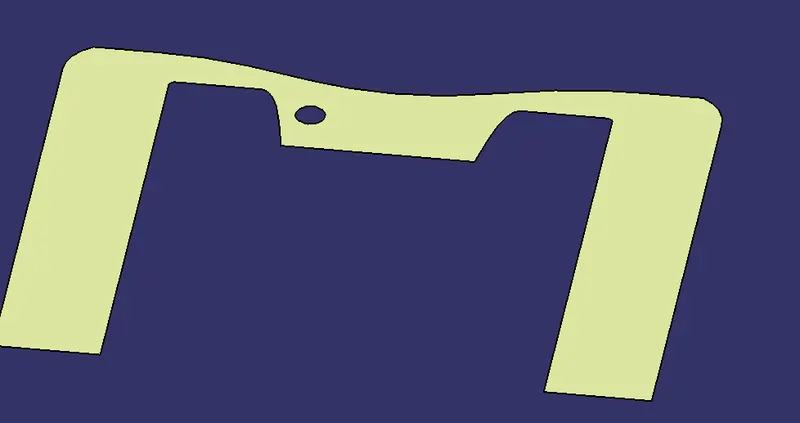
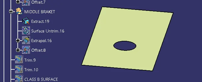
Then use the untrim surfaces command to restore the surfaces up to the limit.
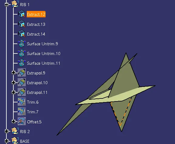
Base: Middle Bracket:
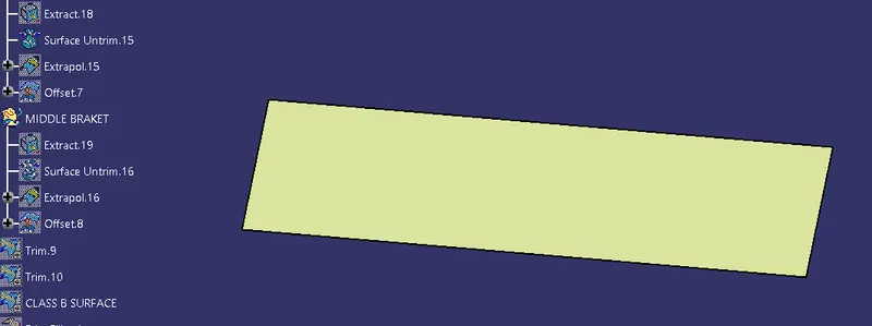
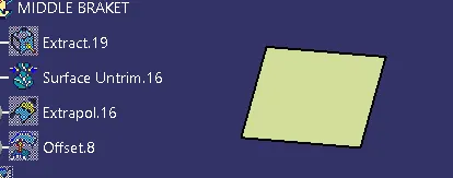
After that click the Extrapol command to extract the surface in the curvature direction.
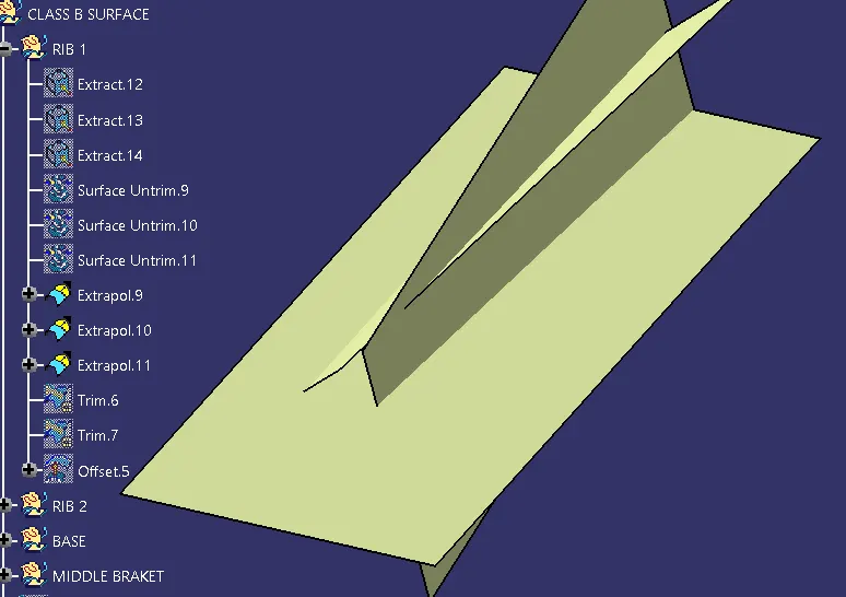
Base: Middle Bracket:
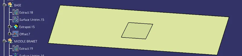
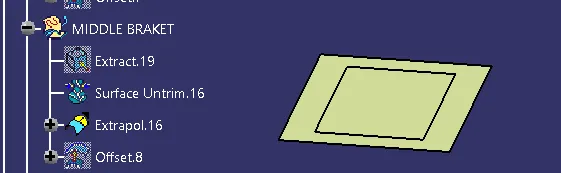
Finally use the trim command to cut the surfaces to get the desired output.
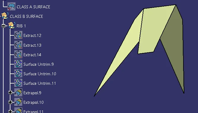
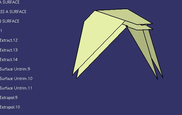
Set an offset to set a thickness of 2.5mm.
Base: Middle Bracket:
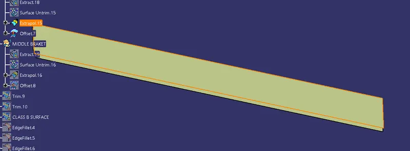
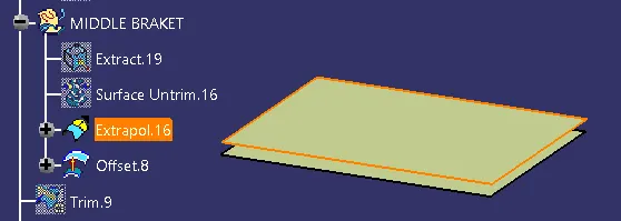
Similarly, do the same process for the second rib.
We get the following parts.
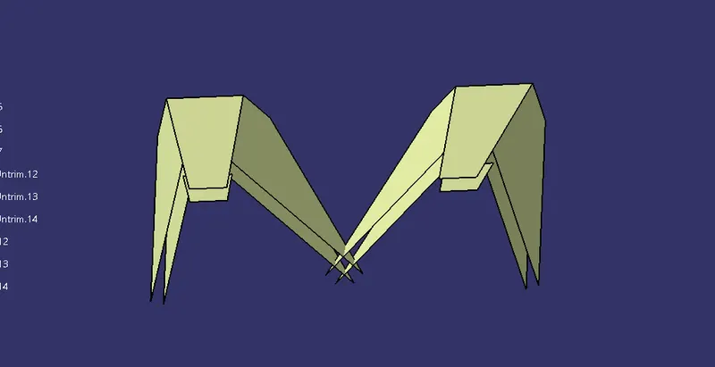
Now all the parts are trimmed to get a Class B surface.
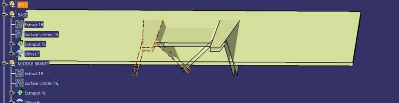
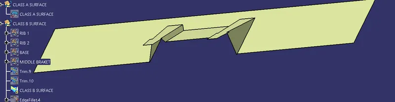
All the fillets are given according to the intersection lines created while the tooling axis was created.
For the fillets add the offset value we selected for giving the thickness of the body for inward thickness add the number but for outward thickness subtract the number to create a uniform thickness all around the shape.
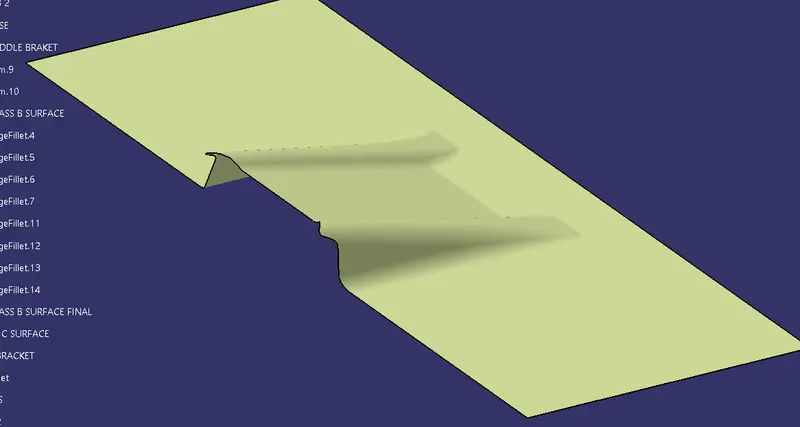
CLASS C SURFACE:
TREE STRUCTURE for creating Class C surface.
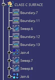
Select the boundary option and click on the boundary of the class A surface to create a sketch of the boundary.
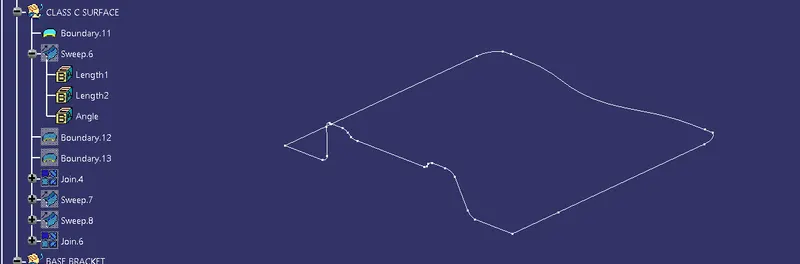
Using sweep command select with draft direction option and set a 3-degree draft to create a sweep of the boundary in Z-axis with angle.
Select the appropriate direction to get the draft.
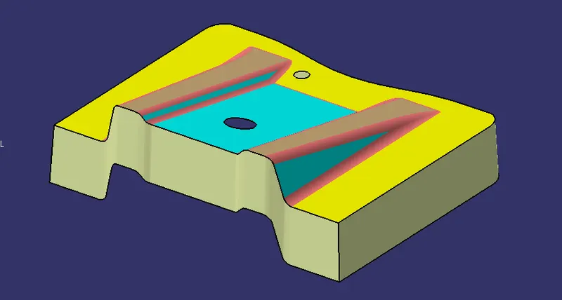
Similarly, create the boundaries for the two holes and sweep it with 3degrees to the draft angle.
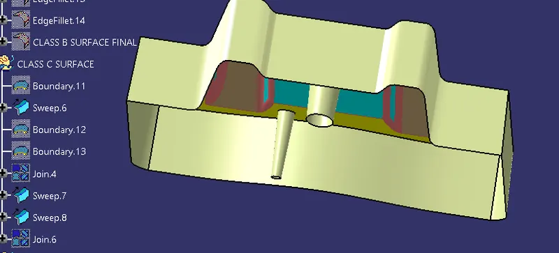
Join all the elements.
THICK BASE BRACKET:
After all the class surfaces are created trim all the elements to get the following.
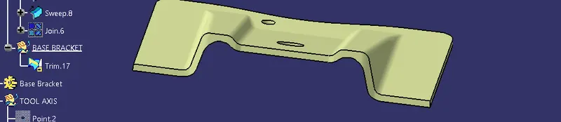
Using the Closed Surface option create a solid part of the bracket.
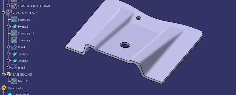
DRAFT ANALYSIS of the SOLID part:
- Select the element to analyze.
- Next click on Use the compass to define the new current draft direction option and make it align with the tooling axis by dragging it to the axis.
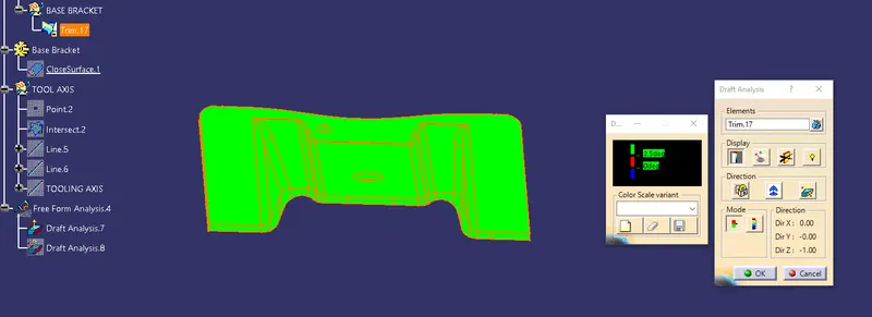
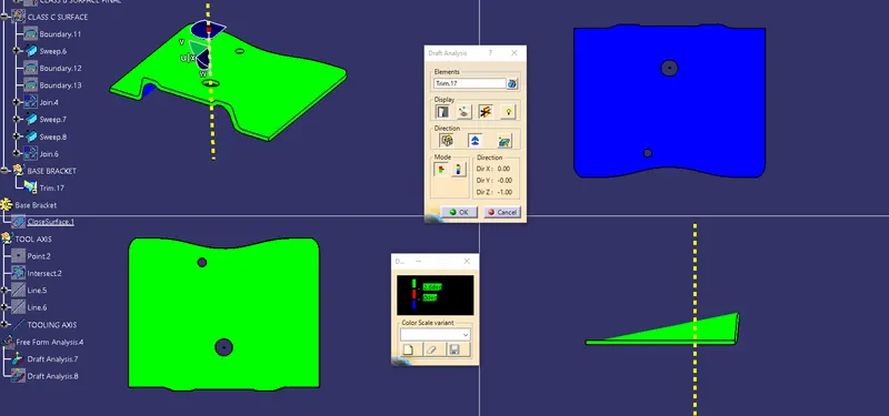
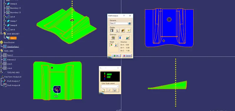
The top right-hand view is the BOTTOM VIEW of the element.
CONCLUSION:
Created a Base Bracket Plastic component through the given Class-A surface and draft analyzed the surface with 2.6 degree of draft angle.
Hence the analysis is conducted adequately.