Week 8 - Challenge 4 - Bumper
Aim:
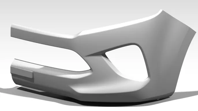
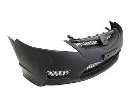
Create the Bumper Plastic component through the given Class-A surface. To begin with, the tooling axis for the given Class-A Surface should be created meeting the requirements of the draft angle and at the end perform the Draft analysis on the model.
Take the Thickness of the component to be 3 mm
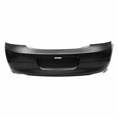
A bumper is a structure attached to or integrated with the front and rear ends of a motor vehicle, to absorb impact in a minor collision, ideally minimizing repair costs. Stiff metal bumpers appeared on automobiles as early as 1904 that had a mainly ornamental function. Numerous developments, improvements in materials and technologies, as well as greater focus on functionality for protecting vehicle components and improving safety have changed bumpers over the years. Bumpers ideally minimize height mismatches between vehicles and protect pedestrians from injury. Regulatory measures have been enacted to reduce vehicle repair costs and, more recently, impact on pedestrians.
Bumpers offer protection to other vehicle components by dissipating the kinetic energy generated by an impact. This energy is a function of vehicle mass and velocity squared. The kinetic energy is equal to 1/2 the product of the mass and the square of the speed. In formula form:
- {\displaystyle E_{\text{k}}={\tfrac {1}{2}}mv^{2}}

A bumper that protects vehicle components from damage at 5 miles per hour must be four times stronger than a bumper that protects at 2.5 miles per hour, with the collision energy dissipation concentrated at the extreme front and rear of the vehicle. Small increases in bumper protection can lead to weight gain and loss of fuel efficiency.
Until 1959, such rigidity was seen as beneficial to occupant safety among automotive engineers. Modern theories of vehicle crashworthiness point in the opposite direction, towards vehicles that crumple progressively. A completely rigid vehicle might have excellent bumper protection for vehicle components, but would offer poor occupant safety.
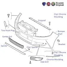
Bumpers are increasingly being designed to mitigate injury to pedestrians struck by cars, such as through the use of bumper covers made of flexible materials. Front bumpers, especially, have been lowered and made of softer materials, such as foams and crushable plastics, to reduce the severity of impact on legs.
International safety regulations, originally devised as European standards under the auspices of the United Nations, have now been adopted by most countries outside North America. These specify that a car's safety systems must still function normally after a straight-on pendulum or moving-barrier impact of 4 km/h (2.5 mph) to the front and the rear, and to the front and rear corners of 2.5 km/h (1.6 mph) at 45.5 cm (18 in) above the ground with the vehicle loaded or unloaded.
Analysis:
The A-surface or the styling surface is first checked for any gaps and other issues in its surfaces. This Surface acts as the input surface so any correction to be done should be with approval from the styling team or done by them. A- perfect surface is the one when a boundary is created, the lines are only on the edges of a component and its holes or cutouts as shown below. (See Image 1)
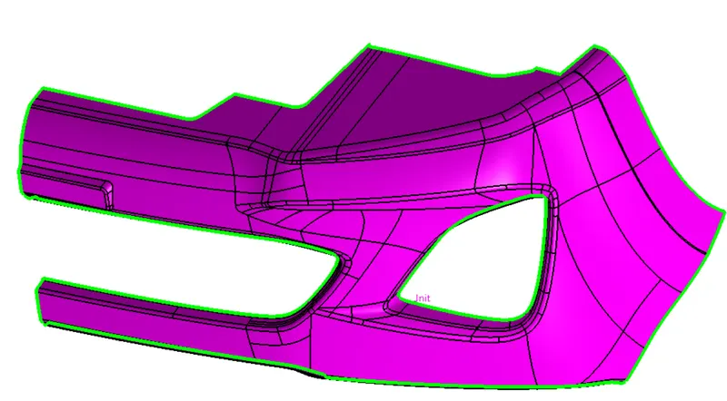
Image 1: A-Surface without any issues when created a boundary
CREATION OF TOOLING AXIS:
Tooling axis is the direction in which a core or cavity of mold opens. This Axis is very important to determine the orientation of the component in mold, core and cavity design.
The tooling axis is created by the inertia method by using the steps as follow
-
Click “Measure inertia” and select the A-surface
-
Click “Create geometry” in the Measure Inertia window.
-
In the Creation of Geometry window, select Non-associative geometry.
-
Click “Center of Gravity”
-
The Inertia point is created.( See Image 2)
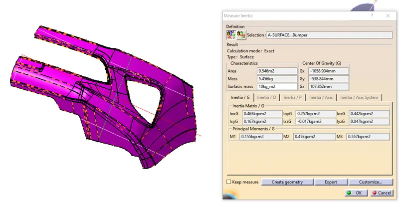
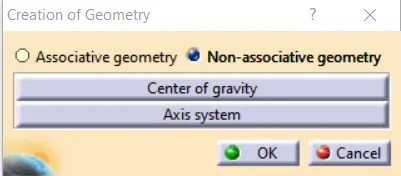
Image 2 : Creation of Inertia point
-
The component is viewed in all axes namely X,Y and Z.
-
It is determined that the X-axis will be the direction for the Tooling axis and a line is created Using the CG point and X-direction as direction of the line.
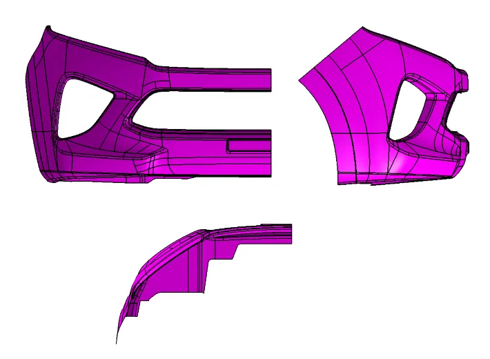
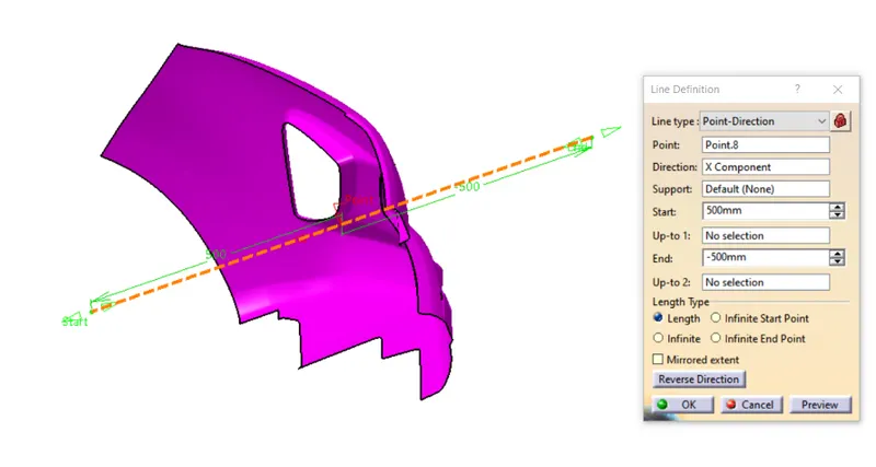
Image 2 : Creation of Tooling Axis
DRAFT ANALYSIS OF A SURFACE:
Draft analysis of the surface is carried to check if the surface or part can be manufactured with the required draft angle.
Draft angle is needed for the component to clear the core and cavity surface as it would have shrunk towards the center while cooling.
The draft angle in this design is 3 degrees. As A surface is a single surface there won't be much difference in color. The draft analysis of A-surface is shown below. (See Image 3 and 4)
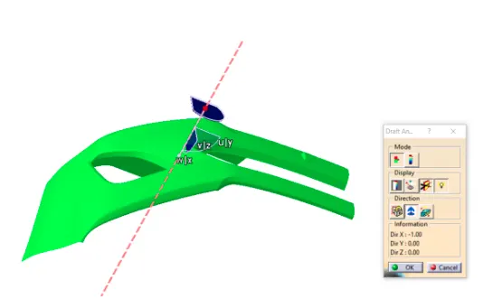
Image 3 : Draft analysis of A-surface
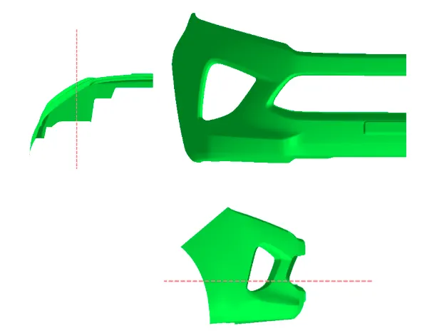
Image 4 : Draft analysis of A-surface , different views
CREATION OF B-SURFACE :
The A-surface is offsetted by 3.00mm as it is the thickness required.
The offset surface is the B-surface but had some issues like in some areas shown in below images.(See Image 5 and 6)
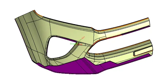
Image 5 : B-surface shown with issues.
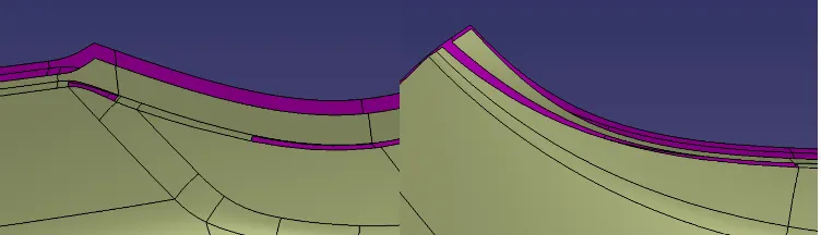
Image 6: Areas in B surfaces where offset was not done
The Areas where the B-surface has issues are corrected by closing them using commands like Multi section,Sweep,Offset and extract.
Finally all the created surfaces are trimmed or joined together with offset surfaces done earlier. This created a single single surface which will act as the final B-surface. (See Image 7)
B surface created is checked for any gaps or errors by creating a complete boundary as shown below.(See Image 8)
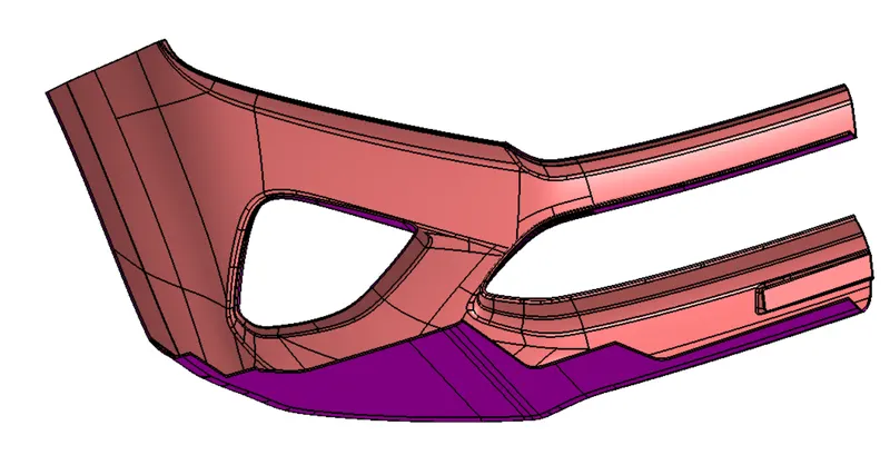
Image 7: A and B surfaces shown
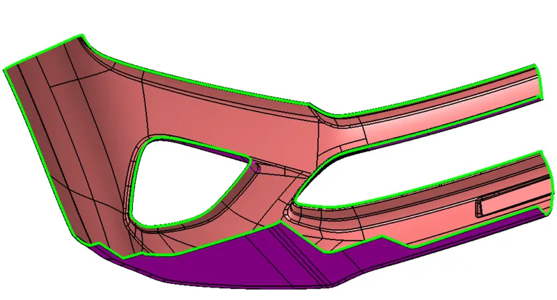
Image 8: Boundary of B-surfaces
CREATION OF C-SURFACE :
The A and B surfaces are connected by another single surface which is called the C surface. (See Image 9)
It is created by using sweep with A surface acting as the reference surface and curve created from the boundary of the same surface.
Sweep with draft direction is also used to create A-surfaces.
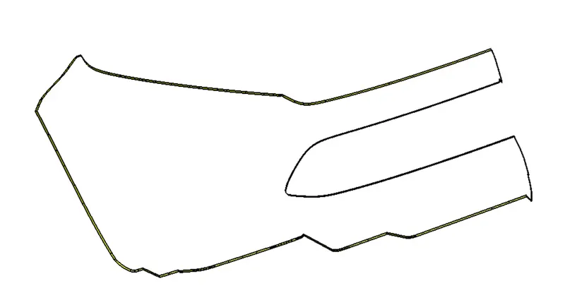
Image 9 : Creation of C surface
CREATION OF CLOSED BODY :
All the surfaces (A,B,C) are joined together to form a closed body.
Boundary is selected and the body is picked. Since an error popped up it can be understood that all surfaces are joined with each other to form a proper closed surface body.(See Image 10)
Finally in part design workbench, using close volume it is changed to a solid body.
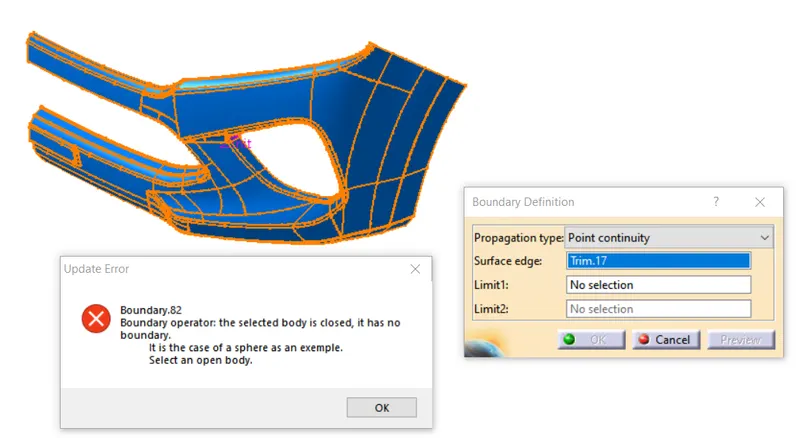
Image 10 and 11 : Checking the closed surface and the solid Bumper body
MODEL TREE:
The model tree created shows that all the geometrical sets are named for clarity.
The publications of Tooling axis, surfaces of A,B and C surfaces are done.(See Image 12)
Also the closed surface body and Volume is published.
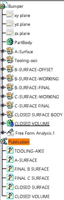
Image 12 : Model tree shown with geometrical sets and publications
DRAFT ANALYSIS OF PART BODY:
The final solid part body has to be analyzed using Draft analysis. This is done to check if all the areas of the body are satisfying the draft angle which is 3 degrees.
A draft angle is a taper applied to the vertical walls of the injection-molded component to assist with releasing the part from the mold.
Draft angles are a required feature of injection-molded custom parts. A functional part for injection molding has to have draft angles that face both the cavity and core sides. This will reduce the risk of damage to the parts and ensure that they can be ejected from the machine.
The Bumper body is checked using Analysis and images for it are shown below.
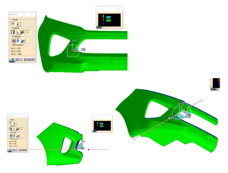
Image 13 : Draft analysis of the Bumper body
Conclusion:
The Draft analysis of the component showed that the component is feasible to be molded without any issues.
Thus it satisfies all design and manufacturing criterias needed for a proper part.
This concludes the report of Design of Bumper Body.