Week 9 - Attachment Feature Creation (Ribs & Screw Boss) - Challenge 1
Aim :- To design the rib and screw boss for the Drill Handle considering the design rules.
Objective :-
- To create a proper tooling direction.
- To perform a draft analysis of the plastic component.
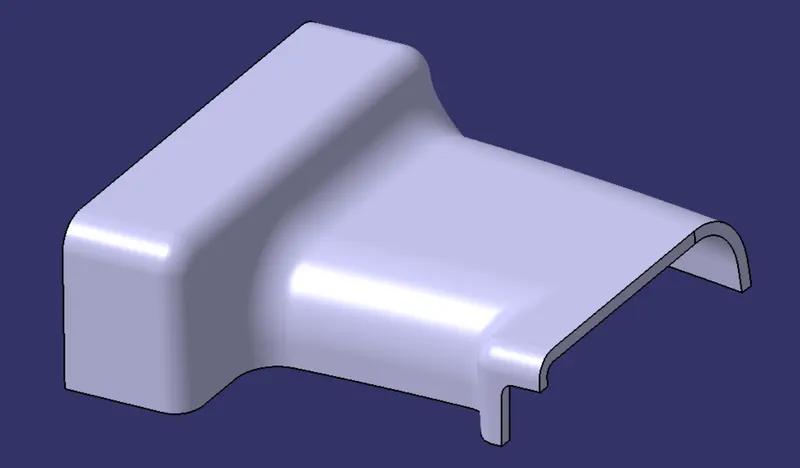
- To create the drill handle plastic component by creating the B-Surface and C-Surface using the given Class-A surface.
- To create the rib and screw boss for the drill handle.
Tooling Direction :-
The tooling axis is the direction in which the mold or core and cavity opens. The ejection of the part from mold depends on the draft. A zero draft can result in difficult or no ejection due to shrinkage. It is recommended to add a minimum of 0.5 to 1 degree of the draft for non-textured surface & 3 to 5 degree of draft for textured surfaces.
Procedure to create the tooling axis using the bisecting method :-
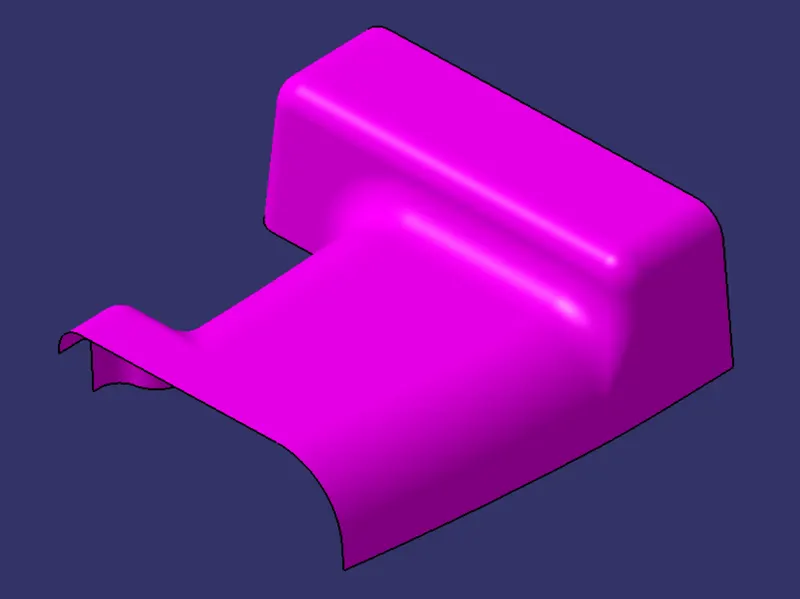
Following Class-A surface is provided to design the drill handle plastic component.
- First of all base face is extracted and point is created at the center of extracted face.
- Intersecting curves are created of Class-A surfaces.
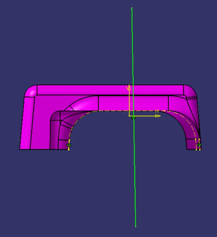
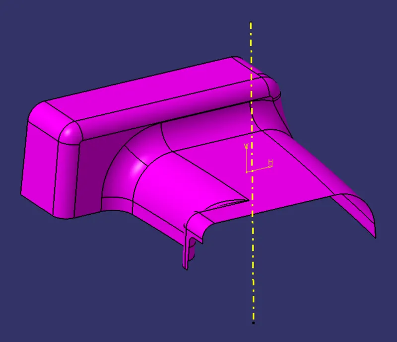
- Lines are drawn to the side faces of the intersected curves then bisecting line is created between these two lines.
- In this way we can create the tooling direction.
Draft Analysis of Class-A Surface :-
B-Surface :-
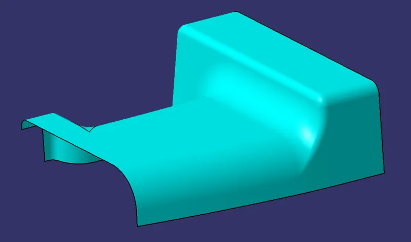
Class B-Surface is extracted from the A-surface and it is offset by 2.5mm in a downward direction.
C-Surface :-
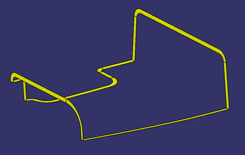
C-Surface connects the class A-Surface and B-Surface. It is created using Sweep command. Boundry of the class A-Surface is swept along the tooling direction.
Trim Surface :-
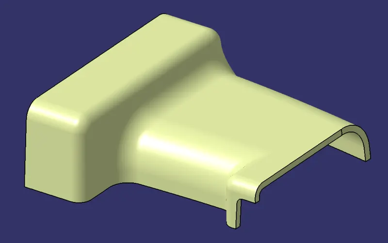
A & C-Surface are joined together then it is trimmed along the B-Surface.
Final Solid Body :-
Design of Rib :-
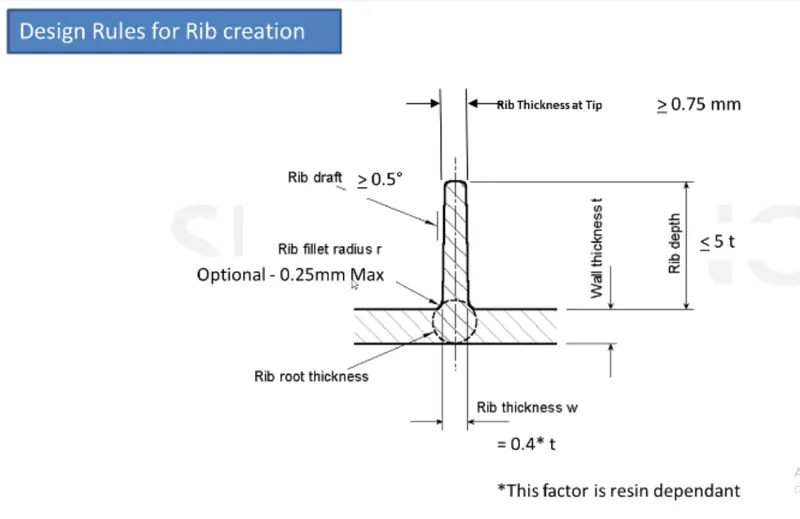
- Draft :- Minimum 0.5 degree per side.
- Thickness :- Typically 40% of wall thickness.
- Height should be less than equal to five times of wall thickness.
- Spacing between two ribs :- 3:1 - Steel height/width ratio maximum.
- Minimum thickness at Tip :- 0.75mm.
- Radii :- 0.25mm maximum.
- Ribs on opposite side of wall should be offset.
- Ribs should be connected to other structural features where possible.
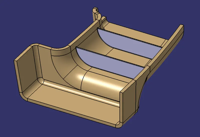
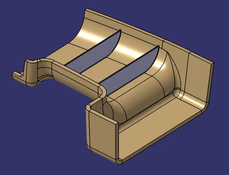
Intersection of Ribs :-
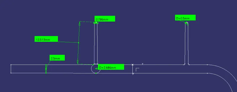
Design of screw boss :-
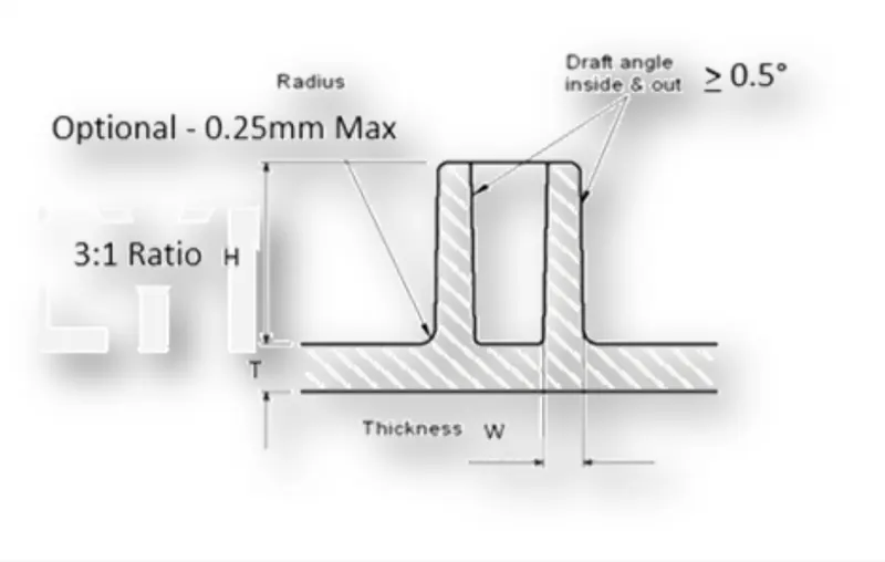
- Draft - 0.5 degrees on the walls of boss
- Thickness - Typically 40%* of the nominal wall at the base.
- Height to Diameter Ratio - 3:1
- Radii - 0.25mm maximum radii.
- Boss gussets must meet rib guidelines.
- Need to plan ahead for type of ejection.
- if less than 25mm tall, draft is not required when sleeve ejection is used.
- Over 25mm tall, draft is required on outside wall only if sleeve ejection is used.
- If sleeve ejection not used, draft is required on all walls.
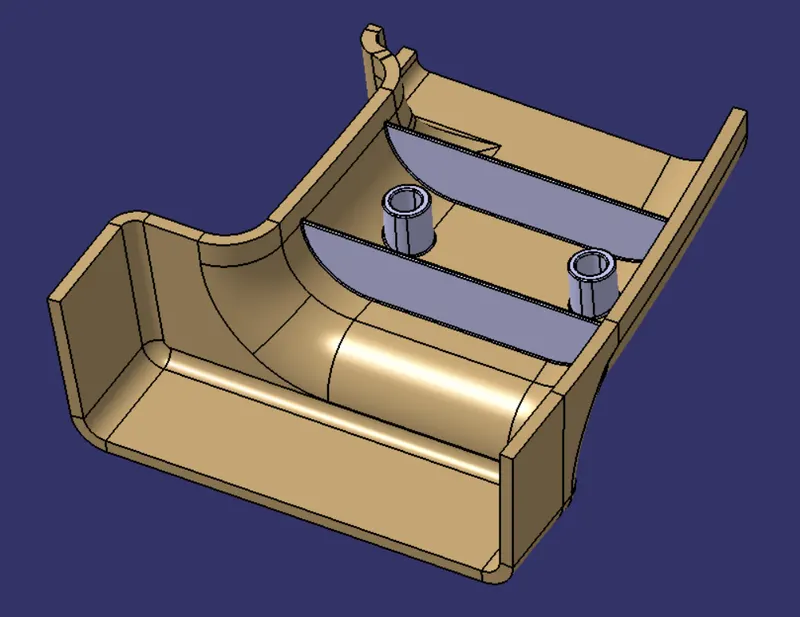
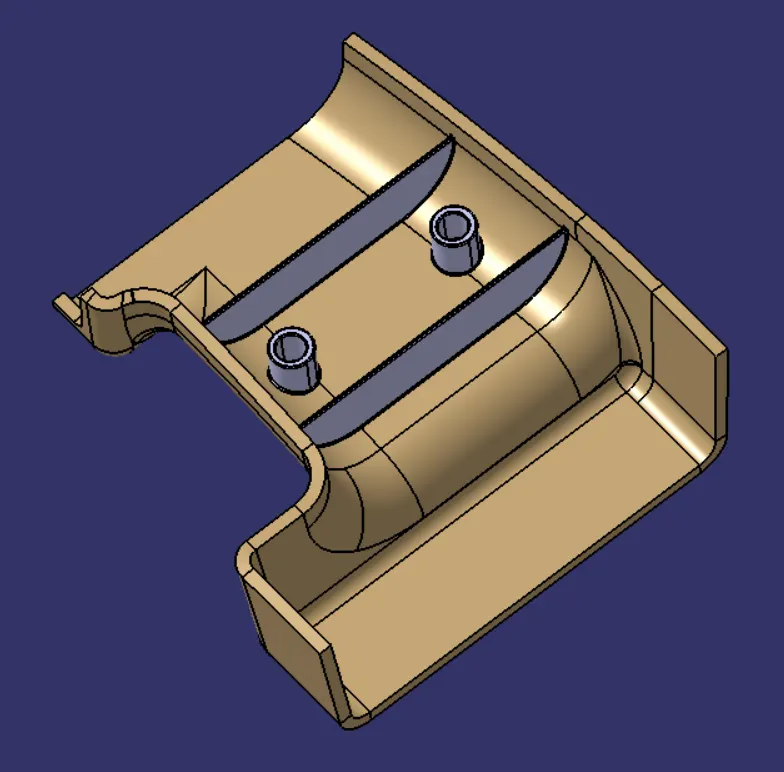
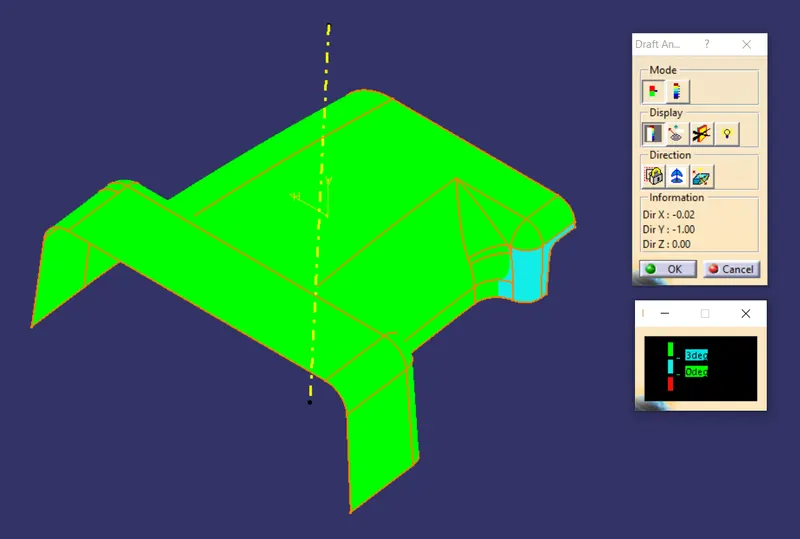
Draft Analysis :-
Draft analysis is performed based on colour ranges identifying zones on the analyzed element where the deviation from the draft direction at any point, corresponds to specified values. Minimum draft angle is considered as 3 degree.
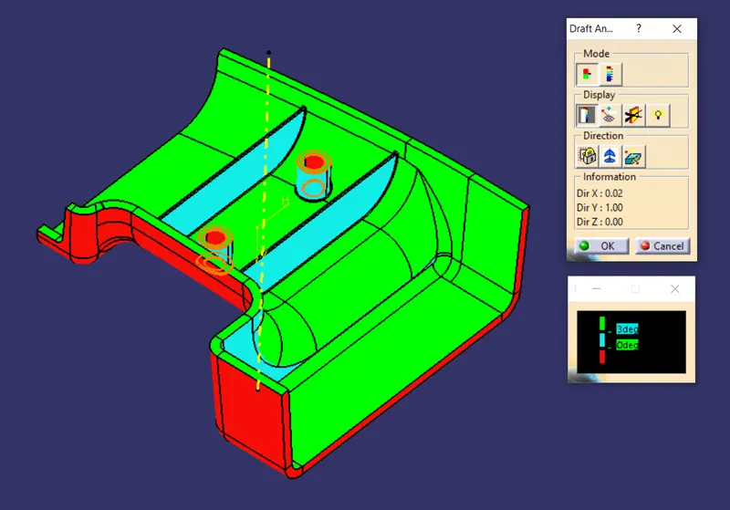
Tree Structure :-
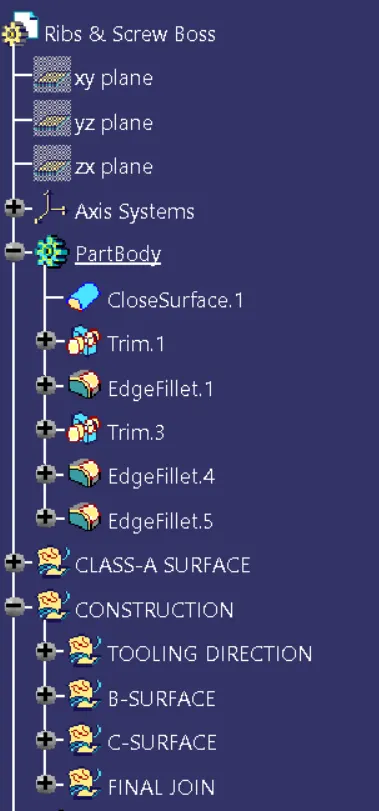
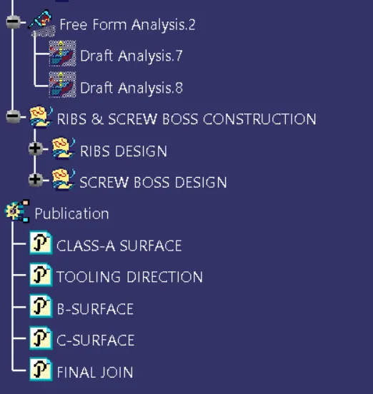
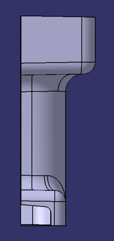
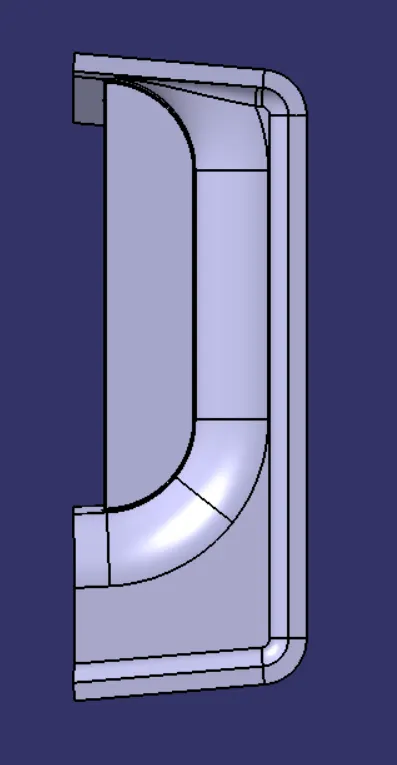
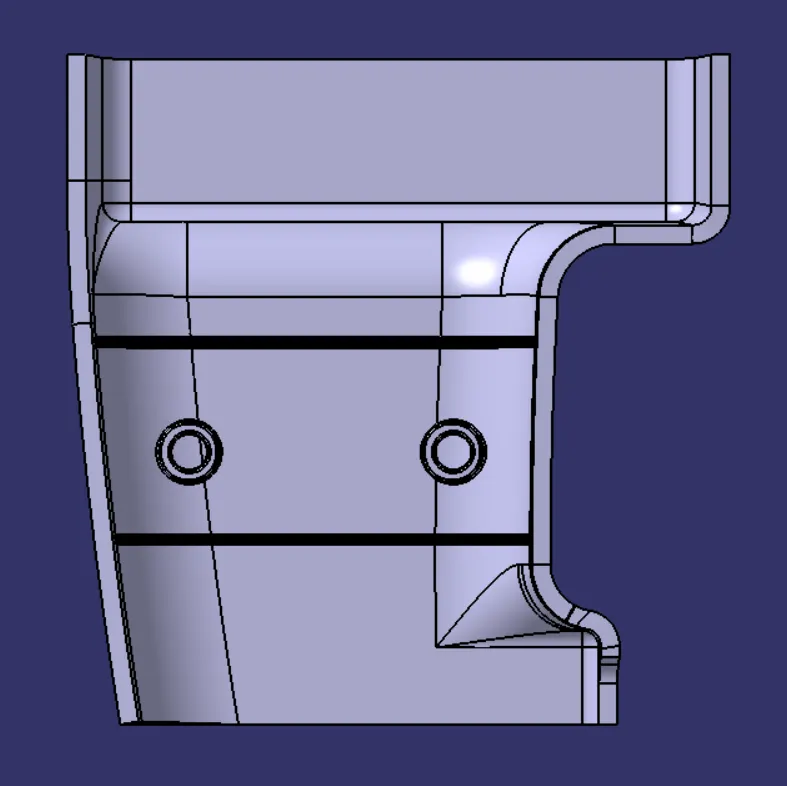
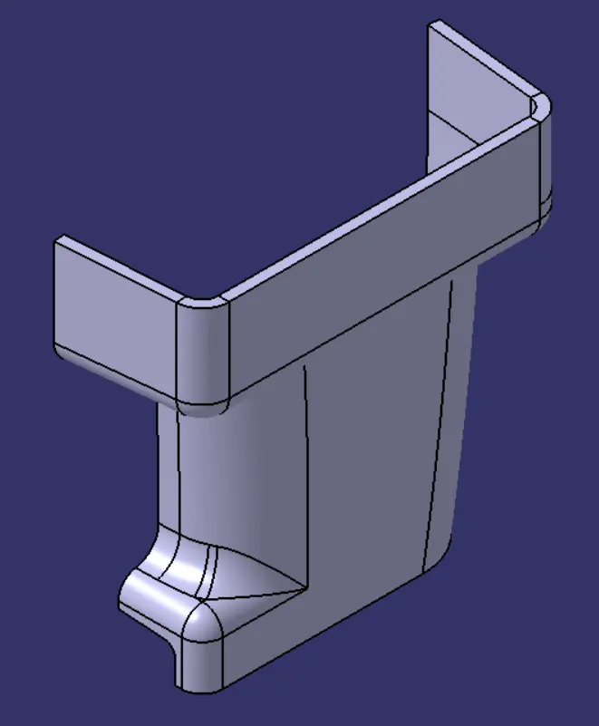
Views of Model
Front View :-
Top View :-
Left Side View :-
Isometric View :-
Conclusion :-
Thus the rib and screw boss for the drill handle has been designed considering the design rules.