Advanced Sheet Metal Design Using NX Cad Challenge_2_Box Assembly
Title :- Advance sheet metal design of box assembly using NX CAD.
Objective :- To design a sheet metal box assembly using NX CAD.
Introduction :-
Sheet metal is metal formed by an industrial process into thin, flat pieces. Sheet metal is one of the fundamental forms used in metalworking, and it can be cut and bent into a variety of shapes. There are many different metals that can be made into sheet metal, such as aluminium, brass, copper, steel, tin, nickel and titanium.
The sheet metal application in NX provides an environment for the design of sheet metal parts used in machinery, Automobile, Aerospace etc. Enclosure, brackets and other parts normally manufactured with a brake press.
Design methodology :-
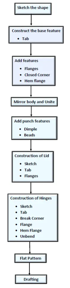
Description of features :-
Construction of box
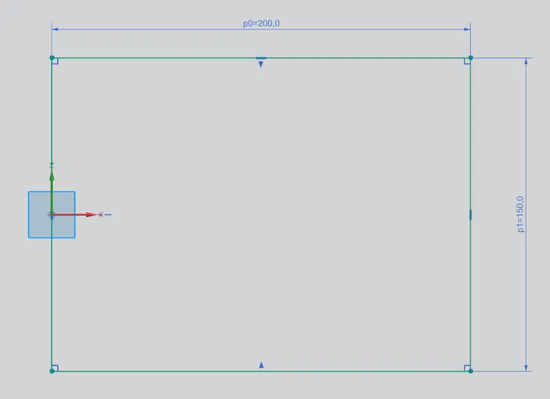
1) Sketch :- A sketch is a combination of two-dimensional (2D) entities such as lines, arcs, circles, and so on. Rectangular base sketch is created.
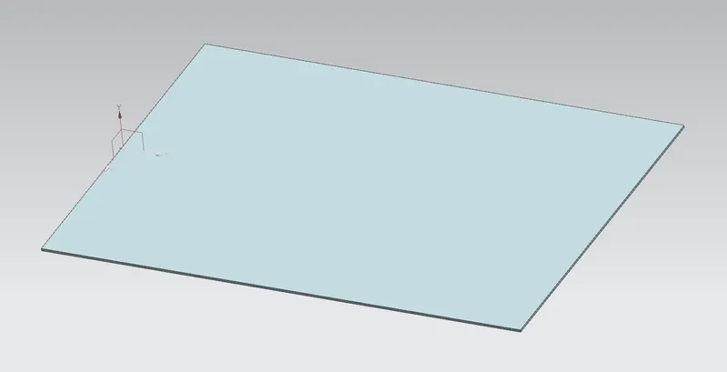
2) Tab :- It is used to create a base feature by extruding a sketch along a vector by a thickness value or adds material to a planar face. Sketch is extruded by 1mm.
3) Flange :- This command is used to add a flat flange at an angle to a planar face and adds a bend between the two. Flanges of 200mm length are created on both sides of rectangular tab.
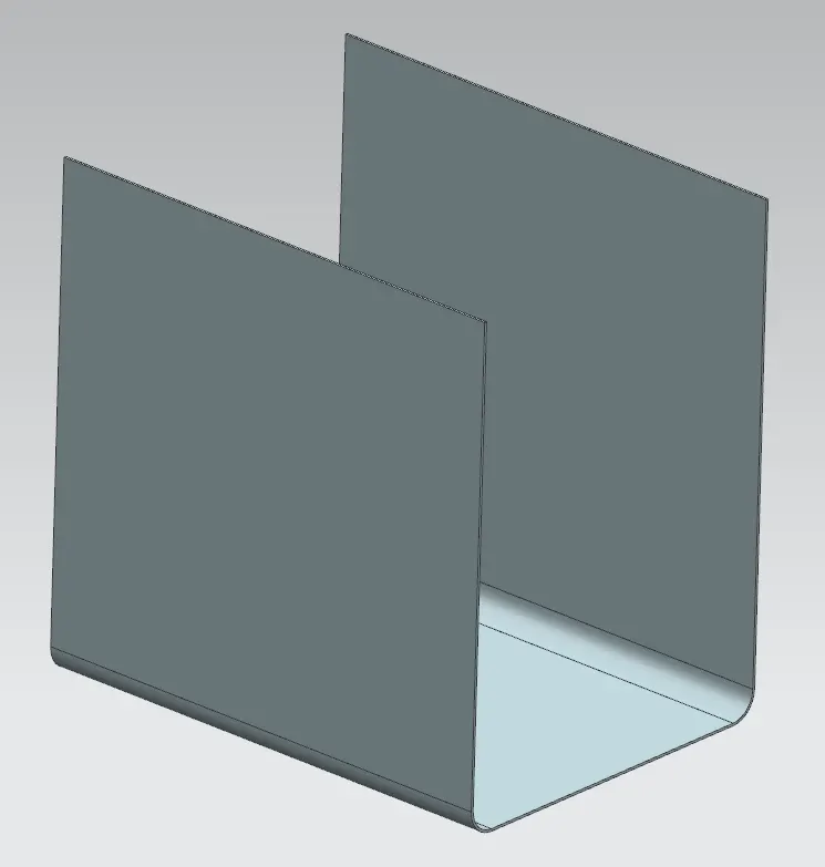
Two more flanges of 70mm length are created normal to XZ plane.
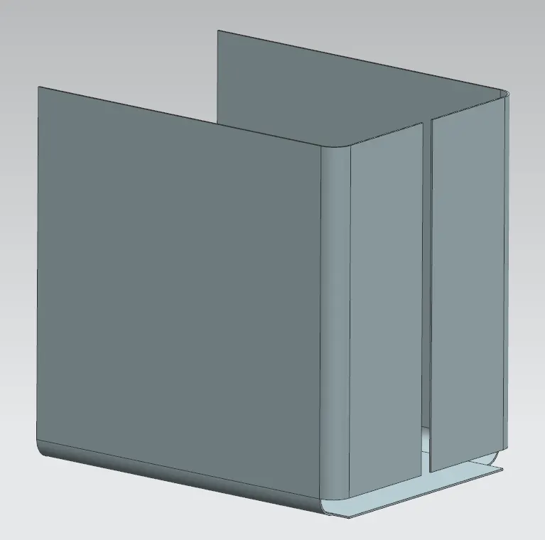
4) Closed Corner :- It is used where two adjacent flanges meet by extending the bends and flanges.
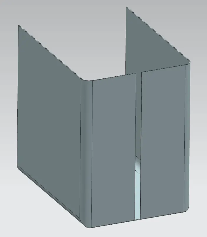
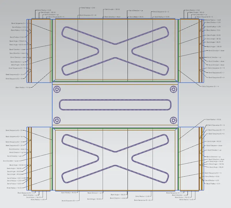
5) Flanges & Hem Flanges :- Flanges of 6.5mm length are created and Hem flanges of 5mm length are created to join the two sheet metal bodies. Hem Flange basically modifies the model by folding the edge of a sheet metal flange over onto itself for the purpose of safe handling or to increase edge stiffness.
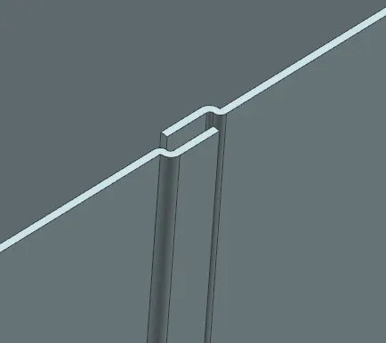
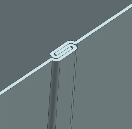
6) Mirror body & Unite :- Mirror body copies a body and mirrors it across a plane. Unite command is used to combine the volume of two or more solid bodies into a single body.
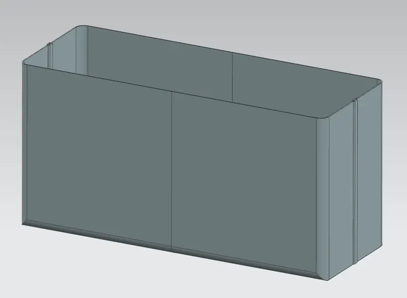
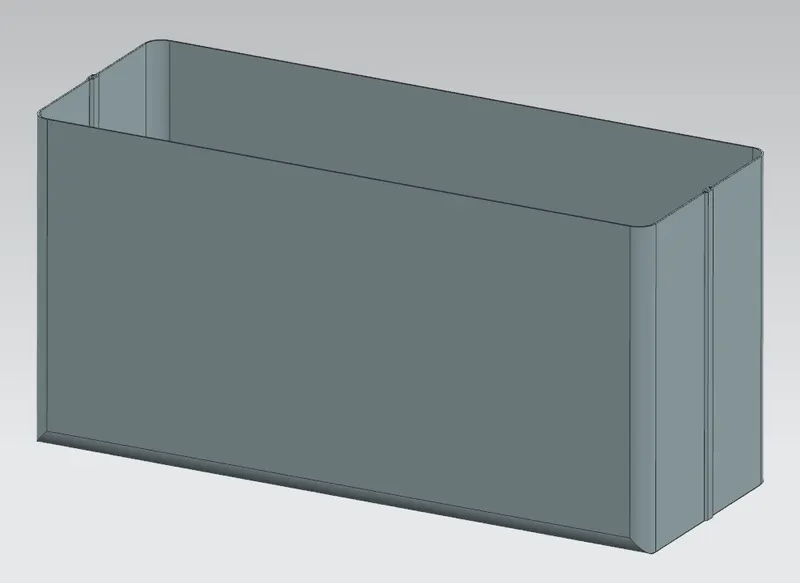
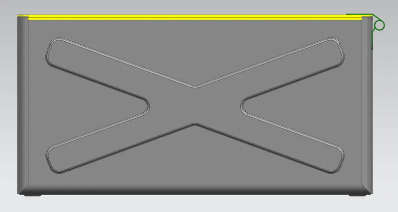
7) Dimple :- It is used to lift an area of the model inside a sketch that simulates a stamping tool. Dimple is generally created to improve the strength of the surface. same feature is mirrored to the opposite face using mirror feature command.
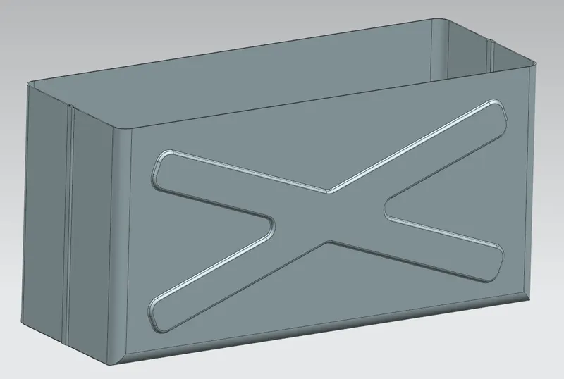
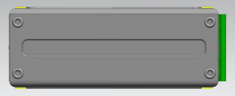
On the bottom face also Dimple is created to improve the strength of the surface.
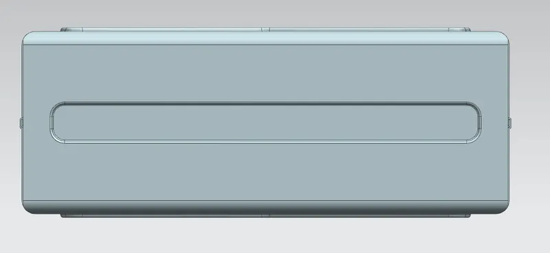
8) Bead :- It is used to lift the material along the contour of a sketch that simulates a stamping tool.
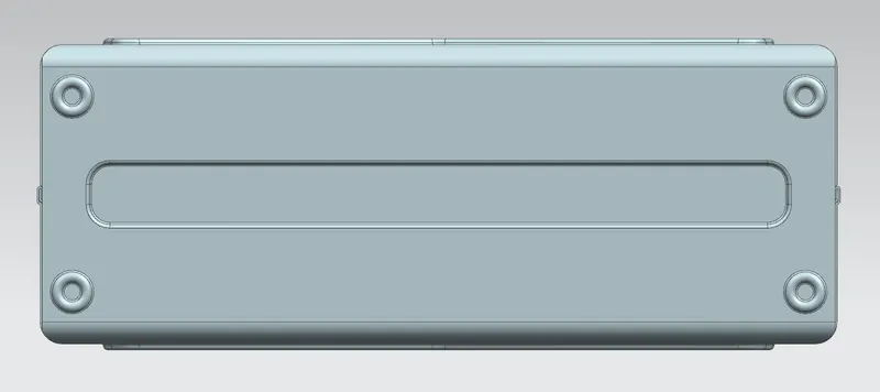
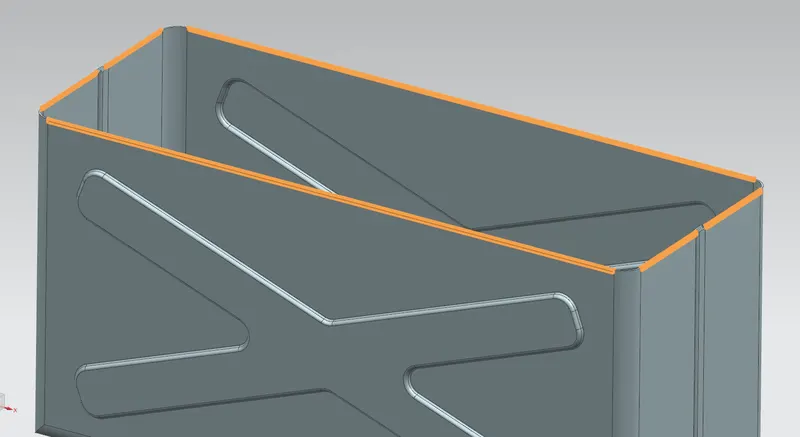
Hem flanges of 2mm length are created on the top edges of box for the purpose of safe handling as well as to increase edge stiffness.
Construction of Lid
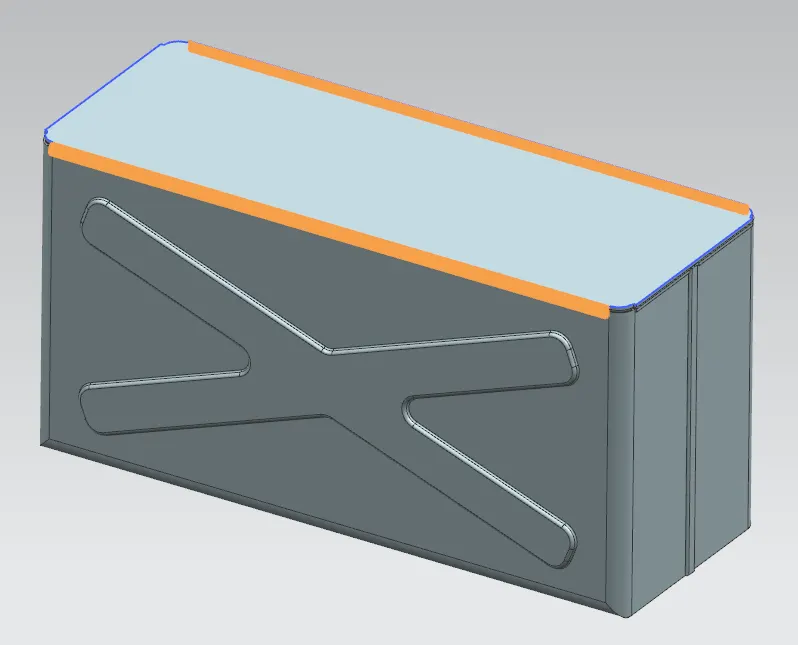
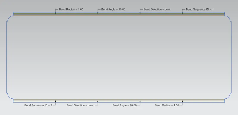
1) Sketch :- Sketch is created by offseting the plane from base surface of the box by 203mm. profile of Lid is created in the sketch.
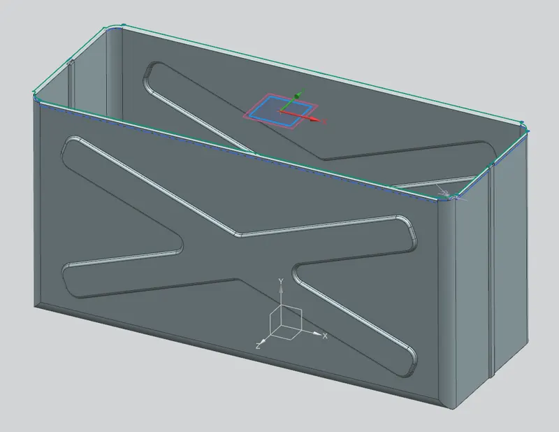
2) Tab :- Sketch is extruded by 2mm in downward direction.
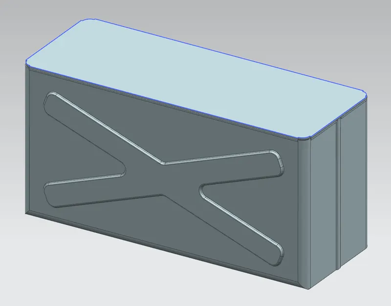
3) Flange :- Flanges are created on both sides of Lid of 3mm in downward direction
Construction of Hinges
1) Sketch :- Sketch is created on the right side surface of the box. Rectangular profile is created on the surface.
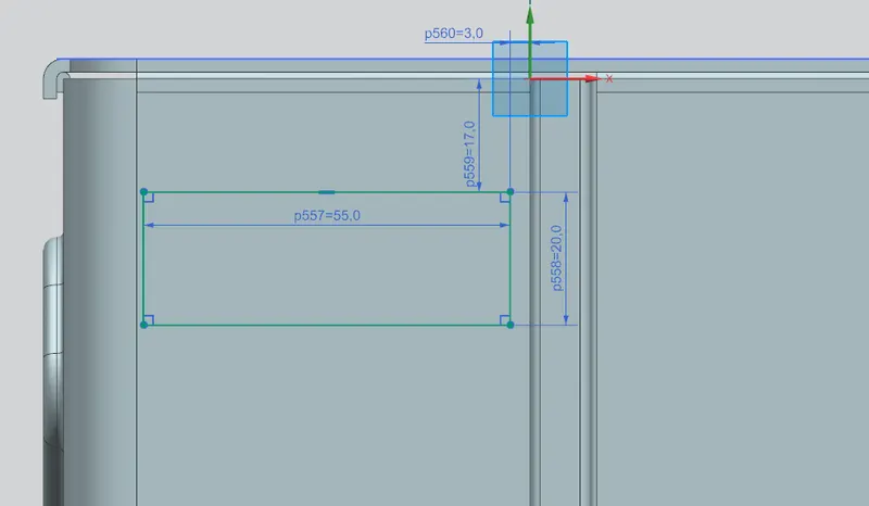
2) Tab :- Sketch is extruded by 1mm in upward direction.
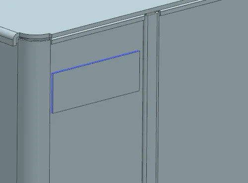
3) Break Corner :- It is used to rounds or chamfers a sharp corner of a tab or flange.
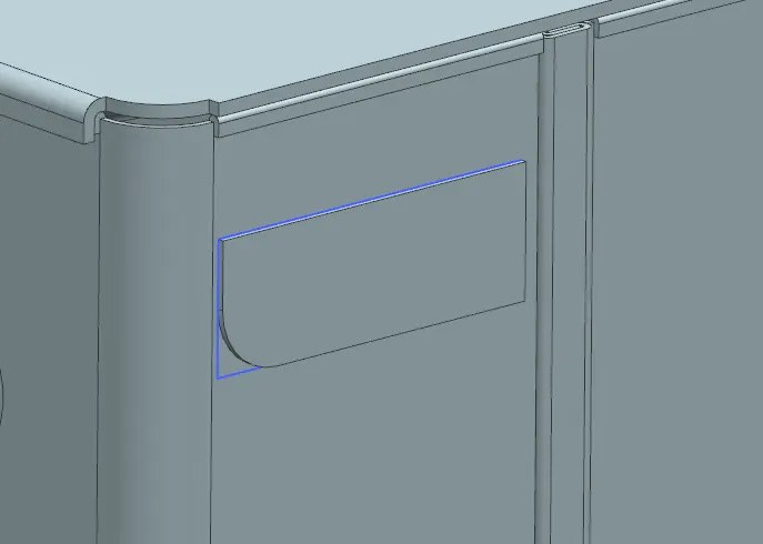
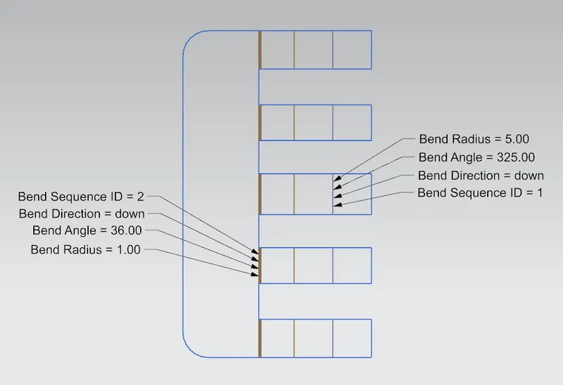
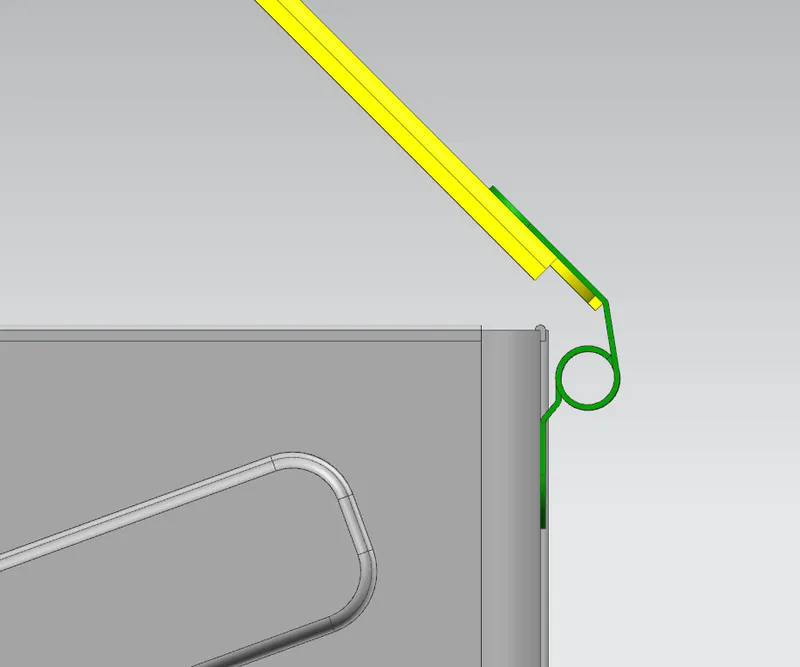
4) Flange :- Two flanges are added of 4mm length at 40degree angle.
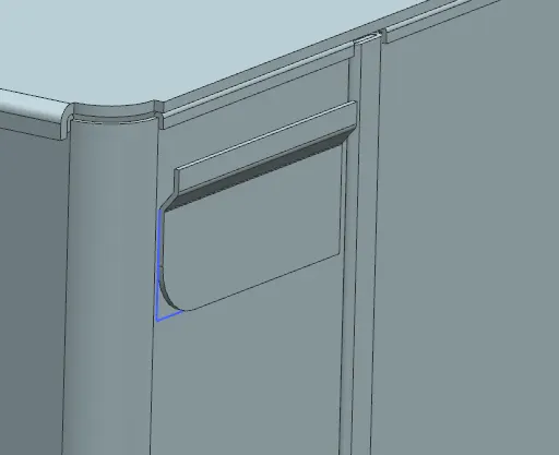
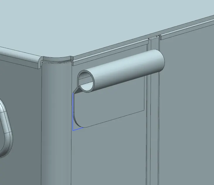
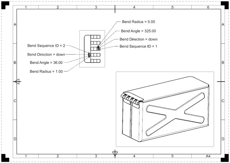
5) Hem Flange :- Open loop Hem flange is created of 5mm bend radius and 325 degree sweep angle from the edge of the flange.
6) Unbend :- It is used to flatten a bend and the material adjacent to the bend.
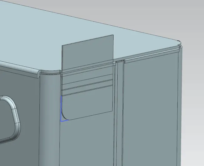
7) Normal Cutout :- First of all sketch is created on the unbend surface the Normal Cutout command is used to Cut the material from solid body. Basically Normal Cutout is used to cut the material by projecting sketch onto the model and then cutting perpendicular to the faces intersected by the projection.

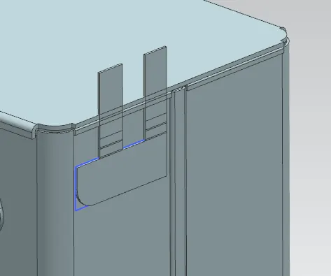
8) Rebend :- It is used to restore an unbend features to its previous bent state, along with any features added after the unbend feature.
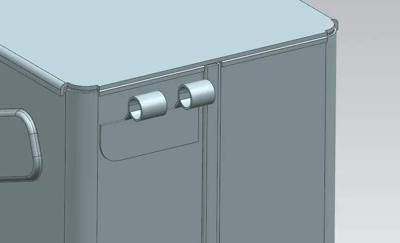
9) Mirror Body :- Hinge portion is mirrored across the XZ plane using Mirror Body command.
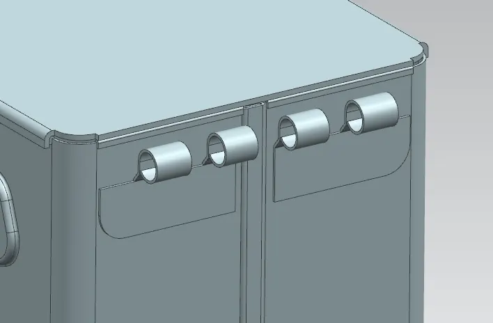
Same procedure is followed to create the upward portion of the hinge
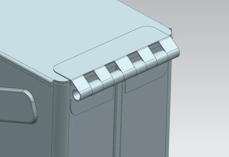
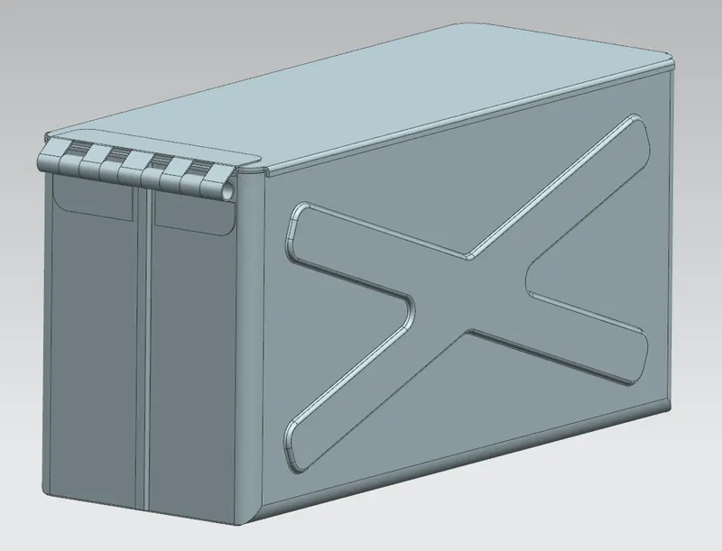
10) Flat Pattern :- It creates a flat pattern feature from the formed sheet metal part.
Box
Lid
Hinge
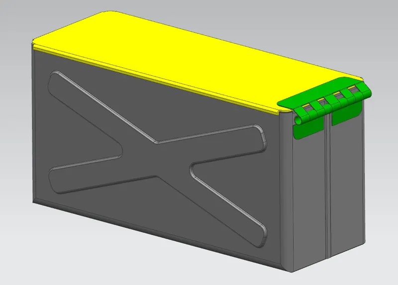
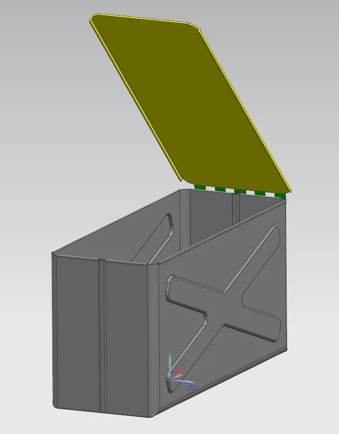
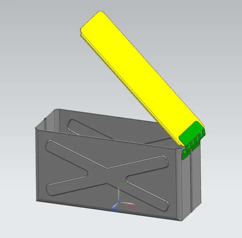
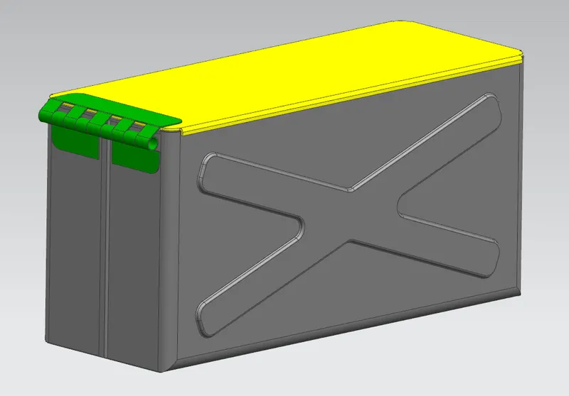
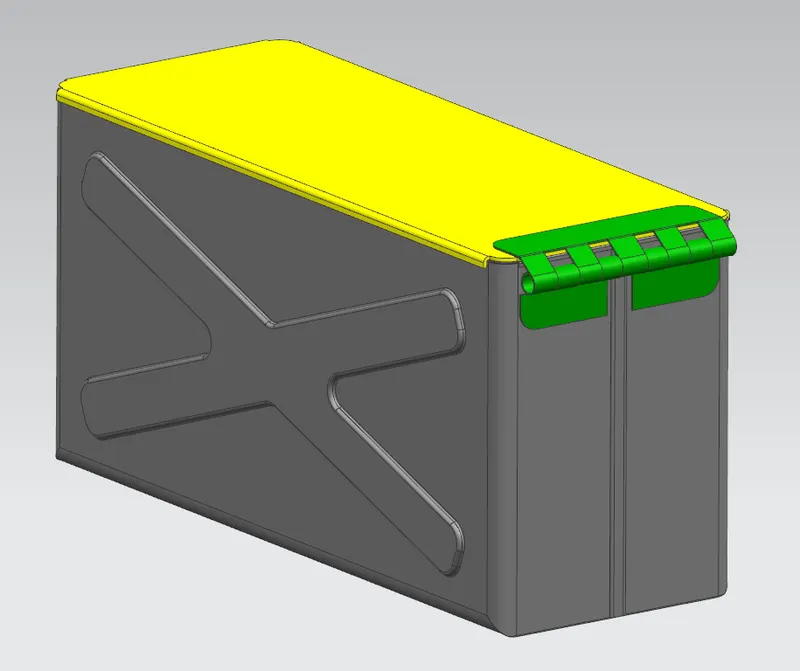
Final Assembly :-
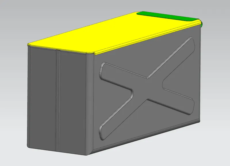
Lid Closed :-
Lid Open :-
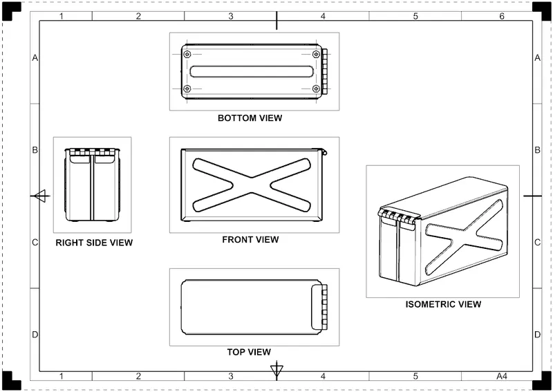
Views of Box Assembly :-
Front View :-
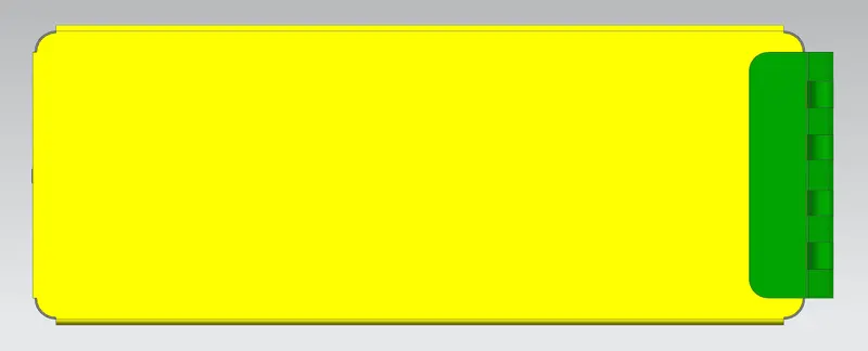
Top View :-
Bottom View :-
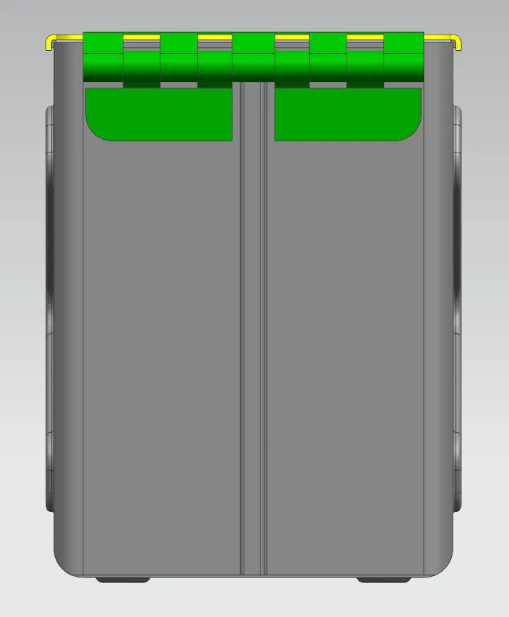
Right Side View :-
Isometric View :-
Drawing sheets :-
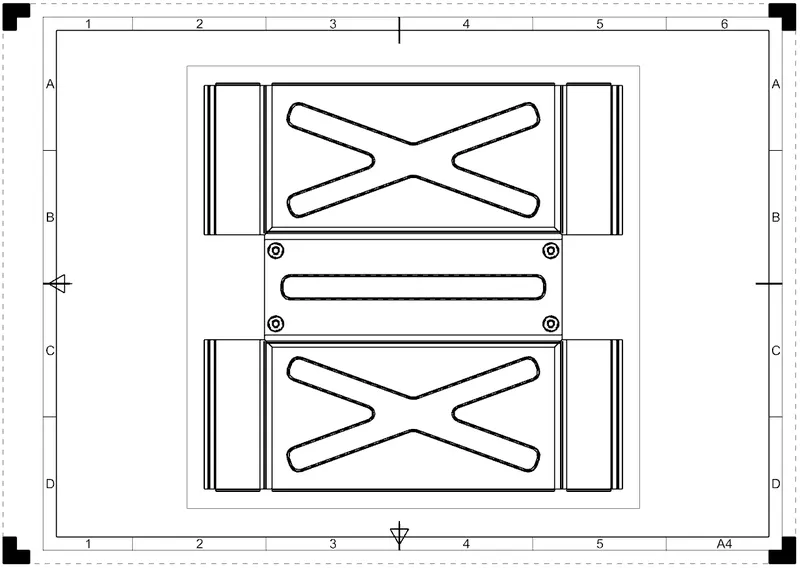
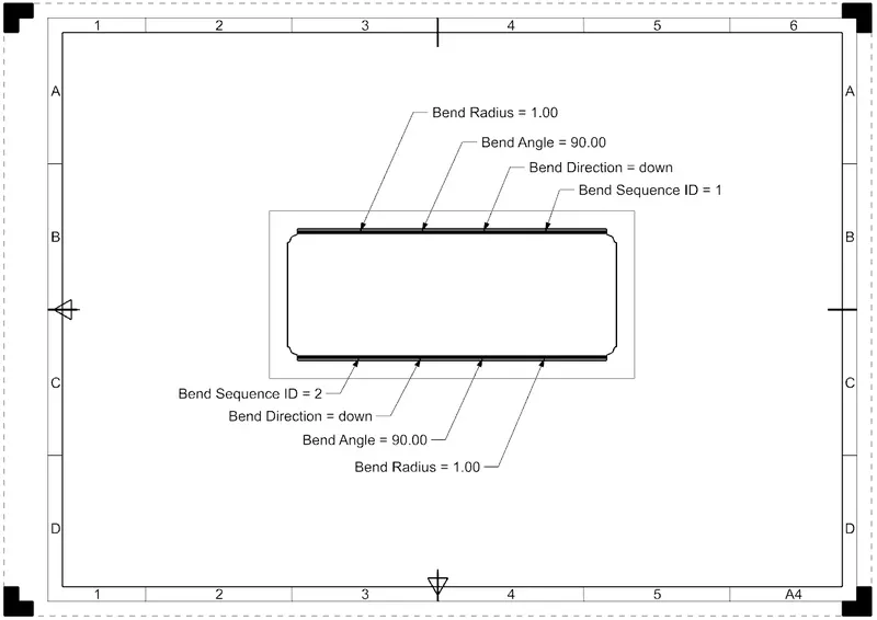
Drafting application is used to create the drawings of designed model.
Conclusion :-
Thus the sheet metal box assembly has been designed using NX CAD.