Week 2- 2R Robotic Arm Challenge
Aim :- To write a program in Matlab to simulate the forward kinematics of a 2R Robotic Arm.
Objective :-
- To study and create a program in Matlab to simulate the forward kinematics of a 2R Robotic Arm.
- To create a animation of working of a 2R Robotic Arm.
Introduction :-
A robotic arm is a programmable mechanical arm. A typical industrial robot arm includes a series of joints, articulations and manipulators that work together to closely resemble the motion and functionality of a human arm (at least from a purely mechanical perspective). The arm contains multiple joints that act as axes that enable a degree of movement. Most industrial robotic arms use four to six joints, which provide the same number of axes of rotation for movement. Robotic arms are fast, reliable and accurate and can be programmed to do an infinite number of tasks in a variety of environments. They are used in factories to automate execution of repetitive tasks like Material handling, Assembly operations, Painting of various equipments or parts in industry, Welding in automobile industry etc.
2R robotic arm contains two kinematic links. A kinematic link or element or link is a resistant body that constitutes part of the machine, connecting other parts which have motion relative to it. In robotic arm links are connected by rotational joint. A rotational joint allows two kinematic links to rotate relative to each other about a fixed axis.
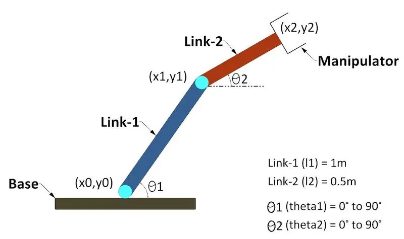
- As shown in the figure Link-1 and Link-2 are the two kinematic links connected by a rotational joint.
- In this program we are considering the length of Link-1 and Link-2 are 1m and 0.5m respectively.
- Link-1 and Link-2 are making θ1 and θ2 angles with horixontal axis.
- Angular motion of both the links is restricted upto 90°.
- To simulate the forward kinematics of a 2R Robotic Arm it is necessary to calculate coordinates of links at different angles between 0° to 90°.
- The (x0,y0) coordinates of Link-1 are considered as origin coordinates (0,0).
- The coordinates of end points of Link-1 can be calculated by trignometric formula.
x1 = L1*cos(θ1) and y1= L1*sin(θ1)
- The start coordinates of Link-2 are similar to the end Coordinates of Link-1.
- The end coordinates (X2,y2) of Link-2 can be calculated by trignometric formula
x2 = x1+L2*cos(θ2) and y2= y1+L2*sin(θ2)
Program :-
%Forward kinematics of 2R robotic arm

clear all
close all
clc

%inputs
%length of links (unit=m)
l1=1;
l2=0.5;

%Angle between the links and horizontal axis
theta1=linspace(0,90,15);
theta2=linspace(0,90,15);

ct=1;
for i=1:length(theta1)
    THETA1=theta1(i);
    for j=1:length(theta2)
        THETA2=theta2(j);
        x0=0;
        y0=0;

        %Calculation of (x1,y1) coordinates
        x1=l1*cosd(THETA1);
        y1=l1*sind(THETA1);

        %Calculation of (x2,y2) coordinates
        x2=x1+l2*cosd(THETA2);
        y2=y1+l2*sind(THETA2);

        %plotting
        plot([x0 x1],[y0 y1],[x1 x2],[y1 y2],'linewidth',3);
        axis([-0.1 1.6 0 1.6])
        pause(0.03)
        M(ct)=getframe(gcf);
        ct=ct+1;
    end
end

movie(M)
videofile=VideoWriter('forward_kinematics.avi','Uncompressed AVI');
open(videofile)
writeVideo(videofile,M)
close(videofile)
Explaination of code :-
Starting the program using commands clear all, close all, clc
- clear all - It is used to clear the workspace.
- close all - It is used to close the previous plots etc.
- clc - It is used to clear the command window.
Step-1 Assigning values to variables :-
In this program length of Link-1 and Link-2 is defined as l1 and l2 respectively. 1 and 0.5 values are assigned to the vaiables L1 and L2 respectively.
To assign the values for θ1 and θ2, linspace(0,90,15) command has been used. It generates the row vector of 15 equally spaced values between 0 to 90.
Step-2 Defining 'for loop' :-
First of all loop counter is defined. THETA1 variable has been defined to assign the values from the (theta1) row vector. For every cycle THETA1 carries one by one values of angle from row vector.
Separate 'for loop' has been used for link-2 as we are going to analyse different positions of link-2 for each angle of link-1 with horizontal. similarly THETA2 variable has been defined to assign the values from the (theta2) row vector.
starting point of Link-1 is defined as x0=0 and y0=0.
Step-3 Calculation of coordinates :-
Values of coordinates (x1,y1) are calculated in every cycle for different values of angles (Theta1).
similarly end values of coordinates of Link-2 (x2,y2) are calculated in every cycle for different values of angles (Theta2).
Step-4 Plotting the Graph :-
Plot command is used to plot the graph of all the x and y coordinates.
Limits for x axis and y axis has been set using 'axis([-0.1 1.6 0 1.6])' command.
pause command is used to pause the command for certain time.
To capture the frame for each cycle 'M(ct)=getframe(gcf)' command has been used. all the captured frames are stored in M variable.
Step-5 Creating animation of 2R robotic arm :-
Movie command has been used to combine all the frames stored in variable M to make an animation.
VideoWriter command is used to assign the video format to the animation.
Open and Close commands are used to open and close the video file.
Output :-
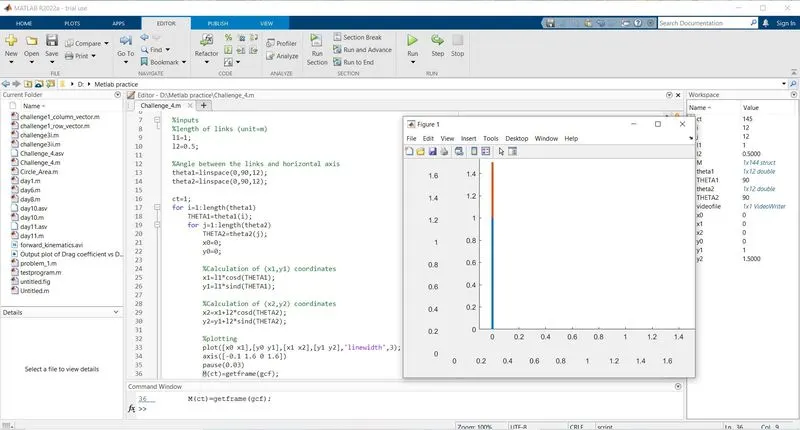
Errors and rectifications-
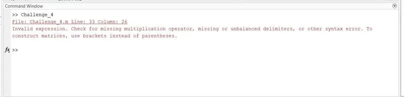
The above error was observed because one square bracket was missing in plot command.
The above error was rectified by adding square bracket.
Output Plot :-
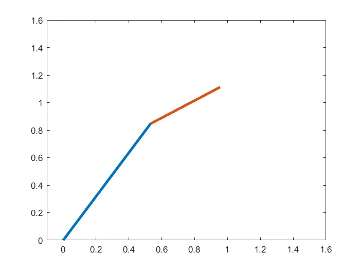
Animation Video of the forward kinematics of a 2R Robotic Arm :-
Here is the link for the video of the forward kinematics of a 2R Robotic Arm