Week 11 - Final project
Aim :- To design the Door Trim panel with mounting features through the given Class-A surface and master sections.
Objective :-
- To create a proper tooling direction for each component.
- To perform a draft analysis of the plastic component.
- To design the four components of the door trim panel assembly by creating the B-Surface and C-Surface using the given Class-A surface.
- To create the mounting features as per design guidelines in the industry.
Introduction :-
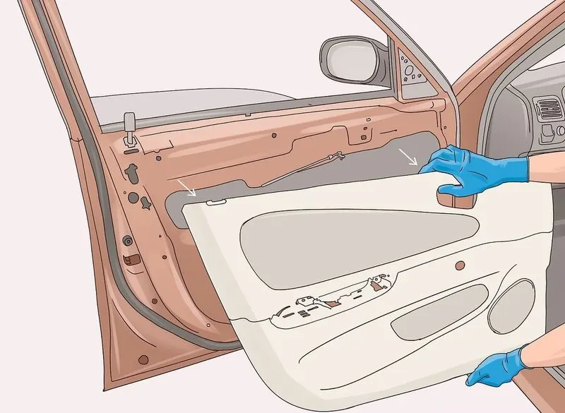
- the door trims are the interior parts that contain the most controls and decorative parts.
- Door trim panel should fulfill functional and safety requirements as well as aesthetic requirements.
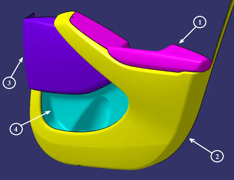
- Assembly of door trim panel consists of four major components.
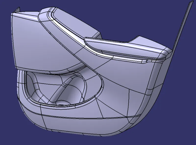
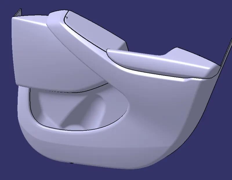
- Door Arm Rest
- Lower Substrate
- Map Pocket
- Bottle Holder
Tooling Direction :-
- In Molding machine arrangement is given to open the mold along a direction which is known as Tooling Direction.
- In other words. The mold is built from two separate halves (Core and Cavity) and tooling direction basically define the direction of mold pulls apart.
- Tooling direction is known as primary direction.
- The ejection of the part from mold depends on the draft. A zero draft can result in difficult or no ejection due to shrinkage. It is recommended to add a minimum of 0.5 to 1 degree of the draft for non-textured surface & 3 to 5 degree of draft for textured surfaces.
Benefits of Draft
- Reduces the chance of damage to the part due to friction during release
- Reduces wear and tear and chances of damage to the mold
- Ensures a uniform, smooth, unscratched finish when required
- Ensures the integrity and uniformity of other surface finishes and textures
- Reduces overall cooling time by lessening or eliminating the need for unconventional ejection setups
- Most, if not all, of these benefits offer either direct or indirect overall production cost reductions.
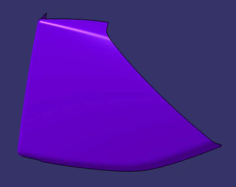
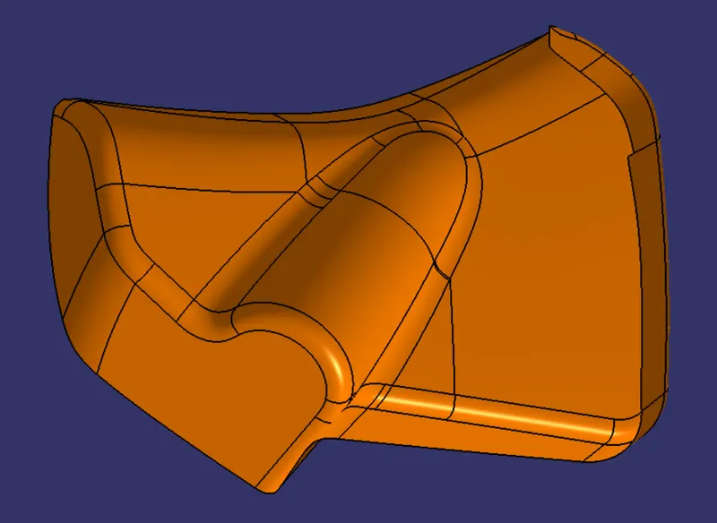
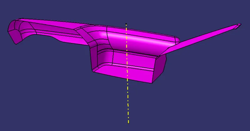
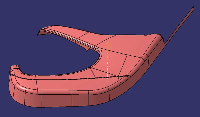
Following Class-A surfaces have been provided to design the components of the door trim panel assembly.
1) Class-A surface for Door Arm Rest :-
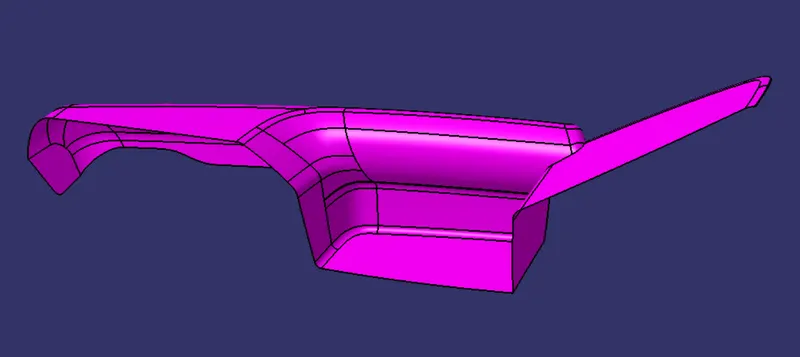
2) Class-A surface for Lower Substrate :-
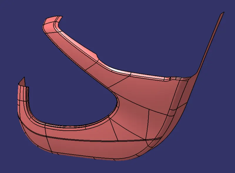
3) Class-A surface for Map Pocket :-
4) Class-A surface for Bottle Holder :-
- First of all base face is extracted and point is created at the center of extracted face.
- Intersecting curves are created of Class-A surfaces.
- Lines are drawn to the side faces of the intersected curves then bisecting line is created between these two lines.
- In this way we can create the tooling direction for each component.
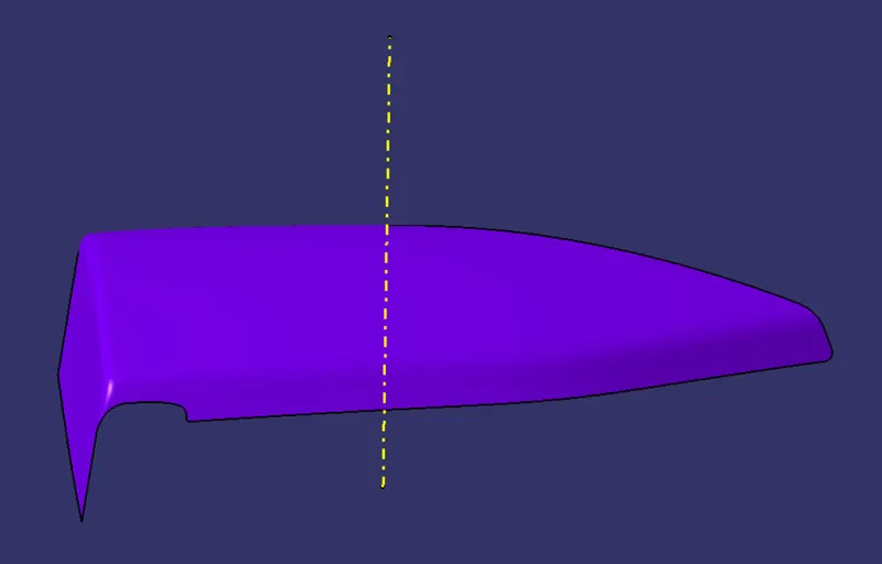
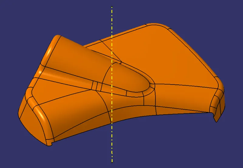
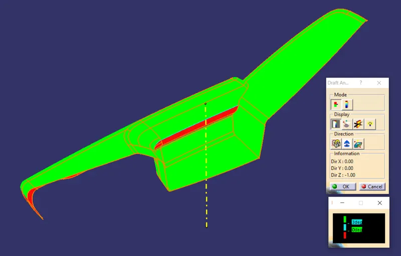
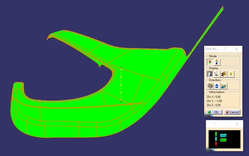
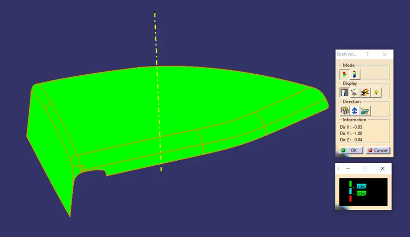
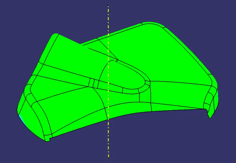
Draft Analysis of Class-A Surface :-
B-Surface :-
Class B-Surface is extracted from the A-surface and it is offsetted by 2.5mm in downward direction.
1) B-Surface of Door Arm Rest
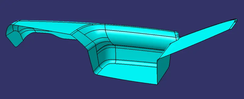
2) B-Surface of Lower Substrate
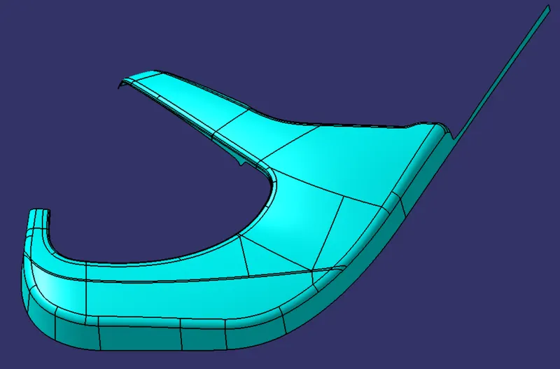
3) B-Surface of Map Pocket
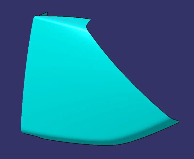
4) B-Surface of Bottle Holder
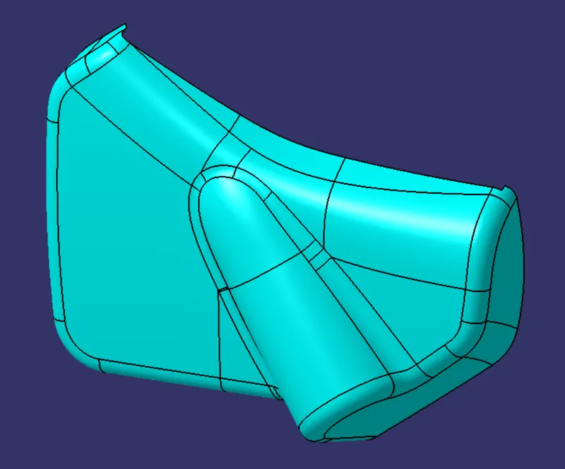
C-Surface :-
C-Surface connects the class A-Surface and B-Surface. It is created using Sweep command. Boundary of the class A-Surface is swept along the tooling direction.
1) C-Surface of Door Arm Rest
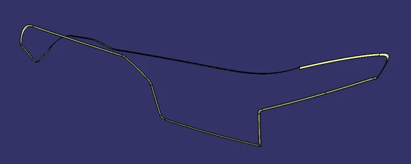
2) C-Surface of Lower Substrate
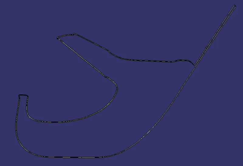
3) C-Surface of Map Pocket
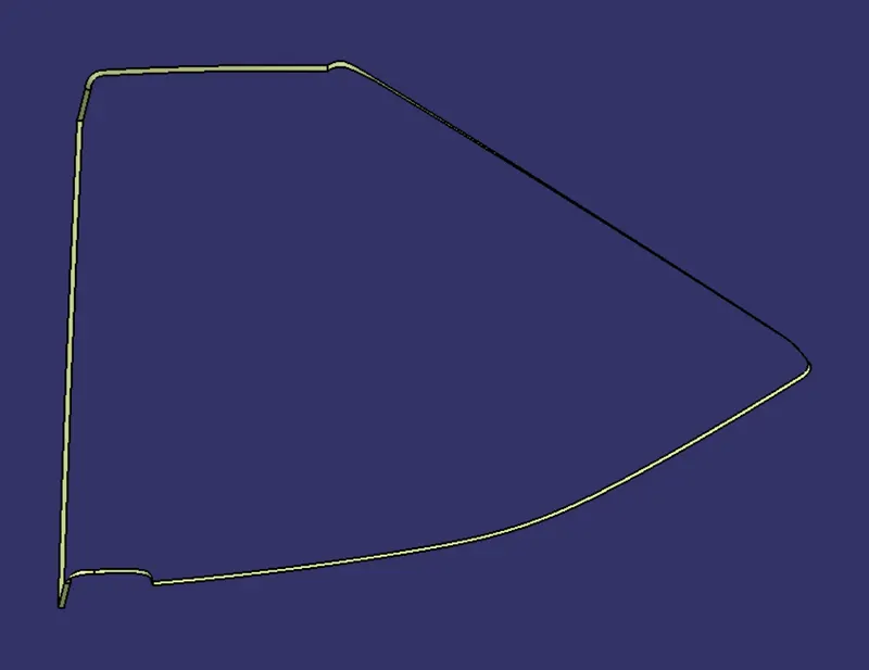
4) C-Surface of Bottle Holder
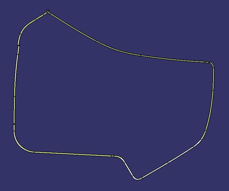
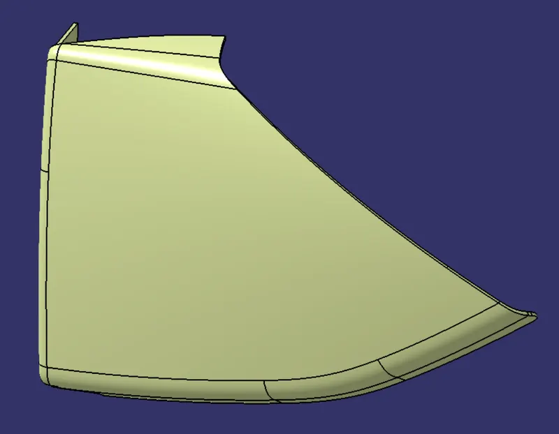
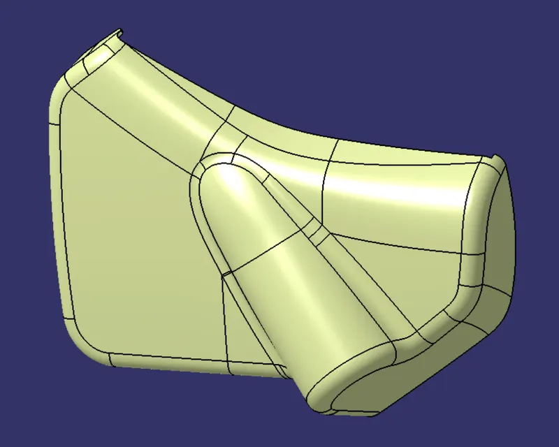
Trim Surface :-
C-Surface is trimmed along the B-Surface then it is joined to the A-Surface.
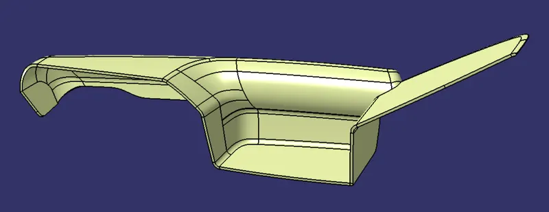
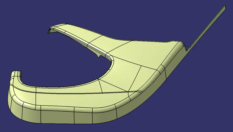
Solid Body :-
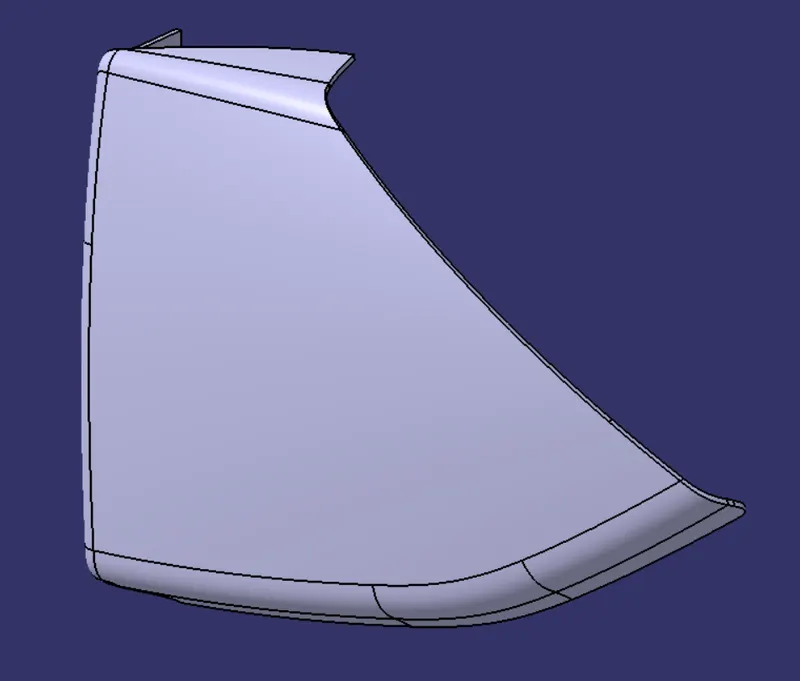
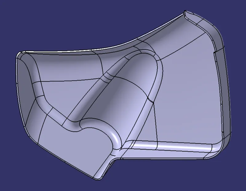
Solid body is created using the Close Surface command.
1) Door Arm Rest
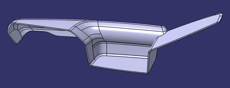
2) Lower Substrate
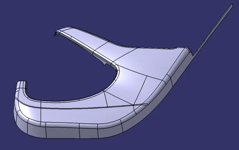
3) Map Pocket
4) Bottle Holder
Engineering Features
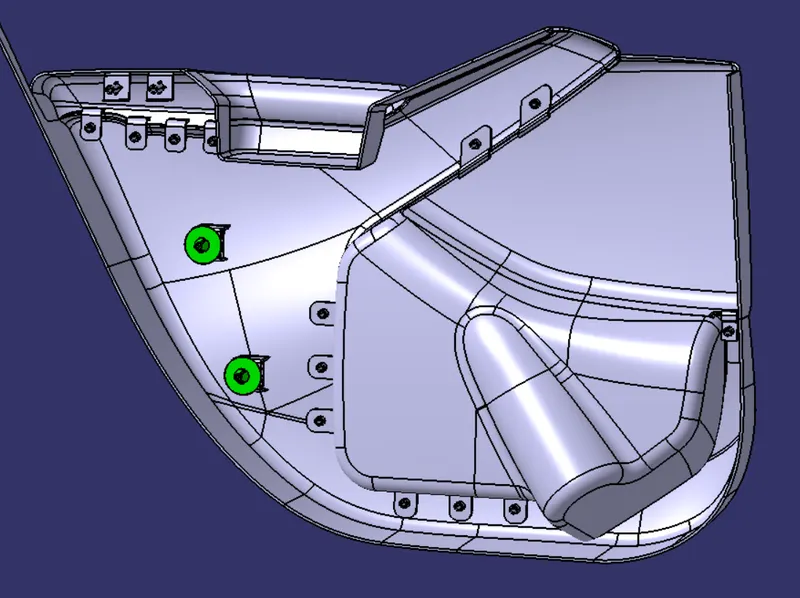
1) Design of the Dog House :-
- The Dog house is the feature used to avoid the sink marks.
- It gives support to the screw bosses, Heat stakes, Push pins, etc. at a specific height from the primary surface of the component.
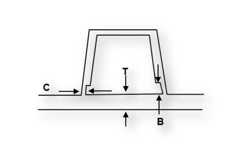
- "C" is where the doghouse contacts the backside of the surface.
- Doghouse wall thickness at the intersection of the part wall ( C ) should be 40% or less than the main wall stock ( T ).
- The height of ( B ) should be between 3.0 – 6.0 mm.
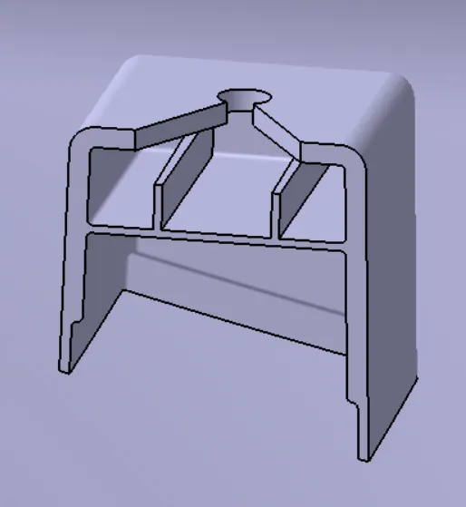
Design of Rib :-
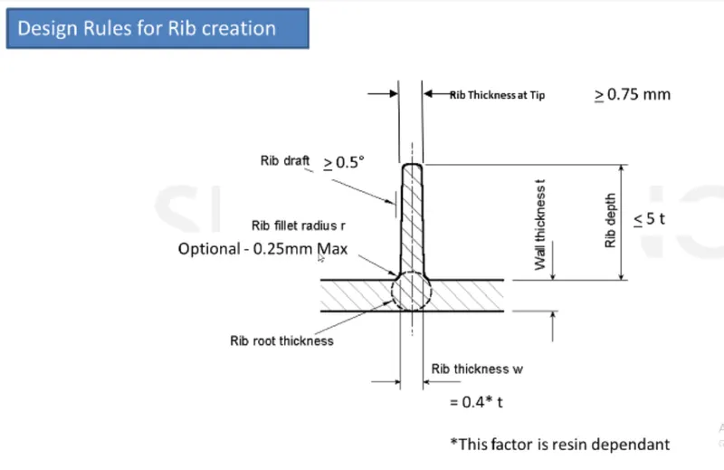
- Draft :- Minimum 0.5 degree per side.
- Thickness :- Typically 40% of wall thickness.
- Height should be less than equal to five times of wall thickness.
- Spacing between two ribs :- 3:1 - Steel height/width ratio maximum.
- Minimum thickness at Tip :- 0.75mm.
- Radii :- 0.25mm maximum.
- Ribs on opposite side of wall should be offset.
- Ribs should be connected to other structural features where possible.
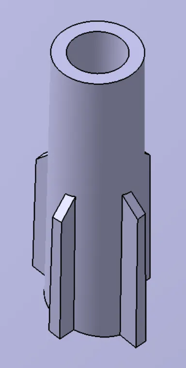
Design of screw boss :-
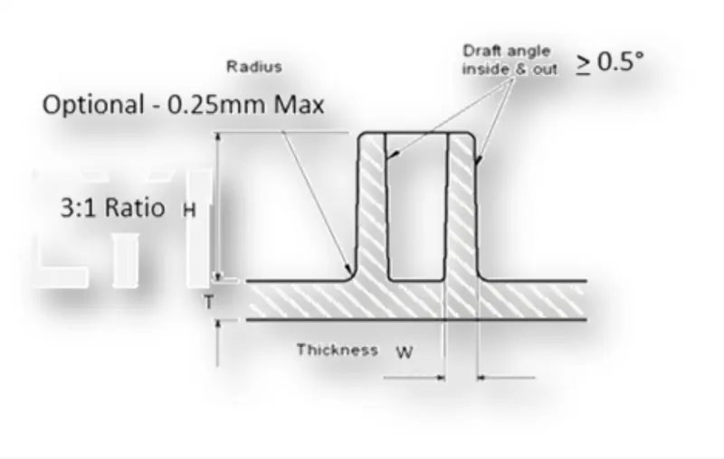
- Draft - 0.5 degrees on the walls of boss
- Thickness - Typically 40%* of the nominal wall at the base.
- Height to Diameter Ratio - 3:1
- Radii - 0.25mm maximum radii.
- Boss gussets must meet rib guidelines.
- Need to plan ahead for type of ejection.
- if less than 25mm tall, draft is not required when sleeve ejection is used.
- Over 25mm tall, draft is required on outside wall only if sleeve ejection is used.
- If sleeve ejection not used, draft is required on all walls.
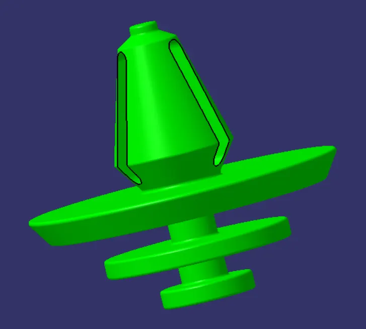
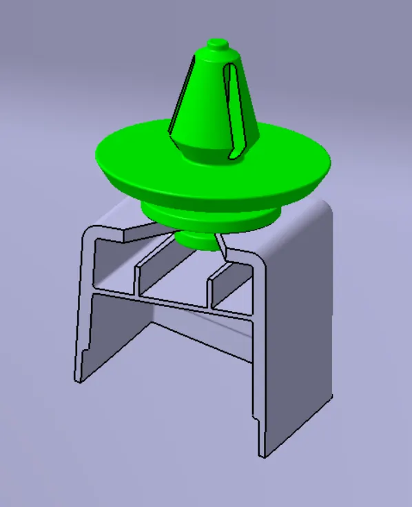
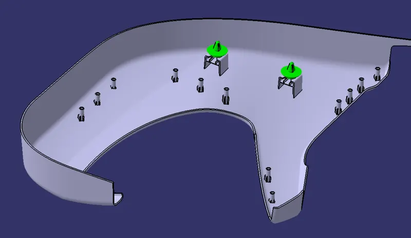
Push Pin Clip :-
- The car door push pin clip is used to connect two parts.
- It is made of plastic material.
- push pins makes assembly very easy.
- They are mounted on the Dog house.
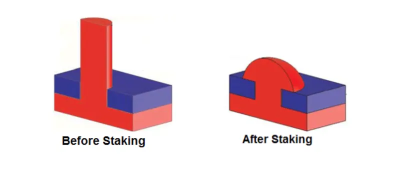
Heat stakes :-
Heat staking also known as thermoplastic staking is the process of joining two dissimilar materials together. In heat staking we use local heating and cooling to raise the temperature of plastic components and allow plastic reforming to be carried out.
Flanges :-
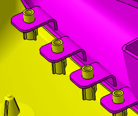
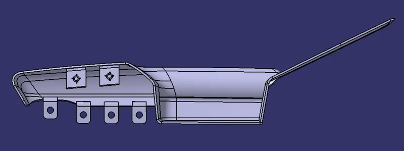
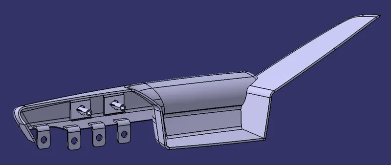
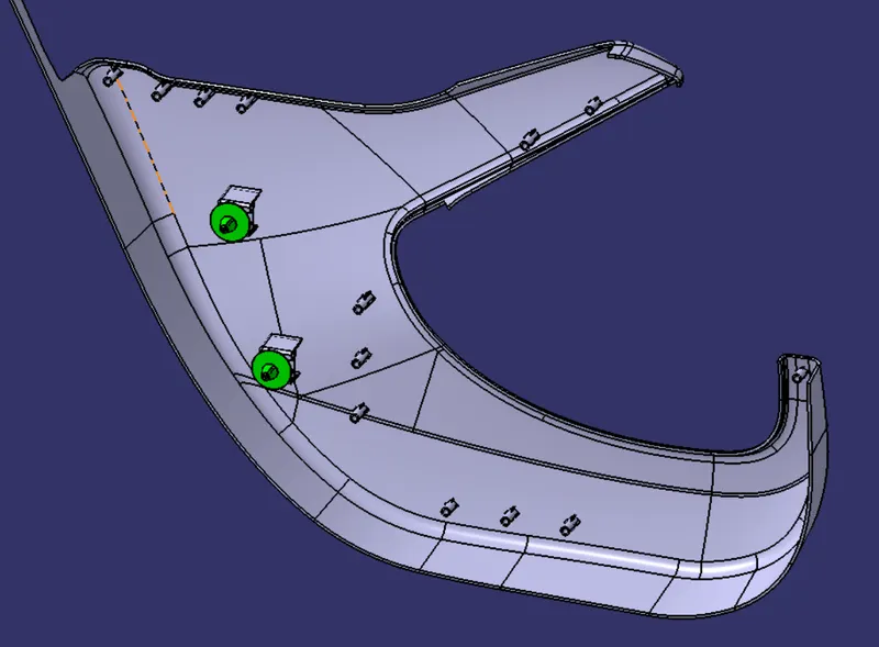
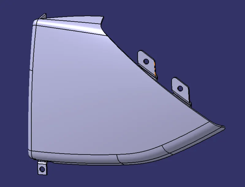
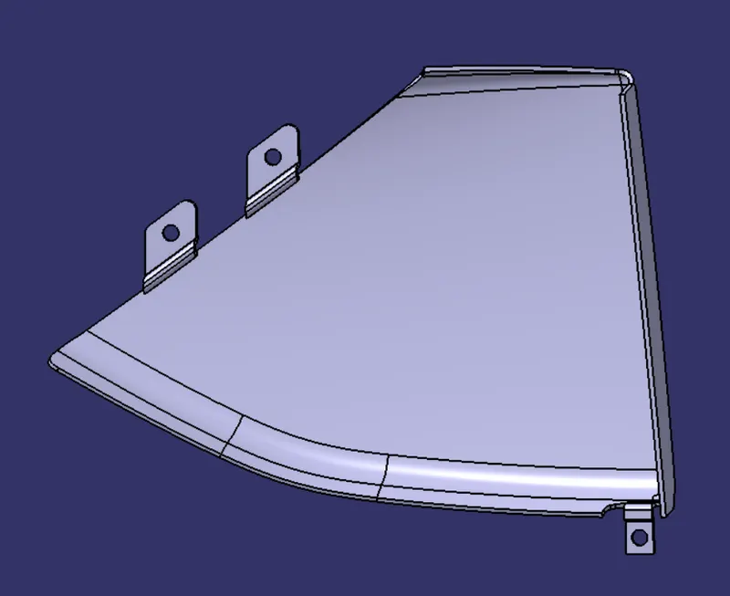
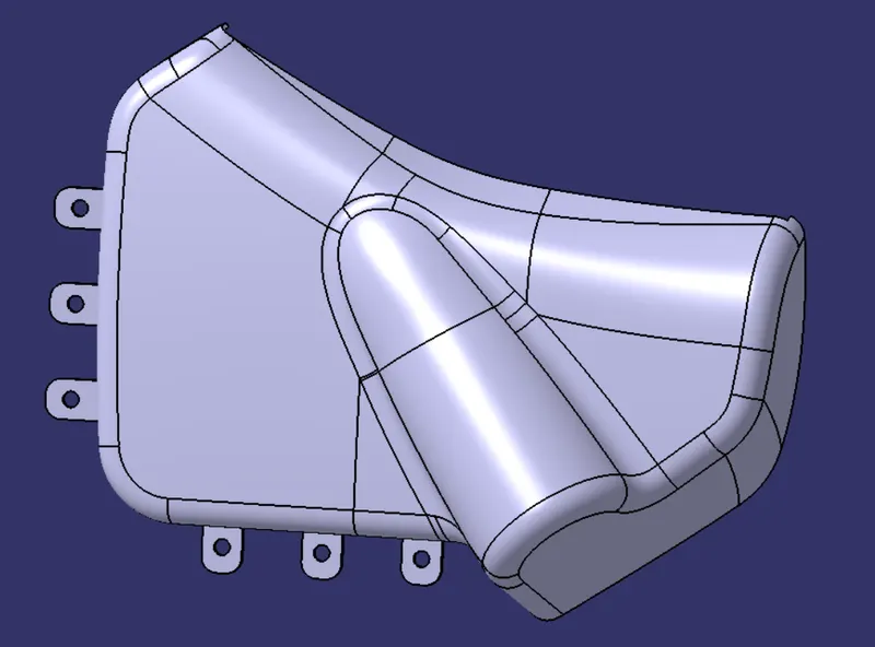
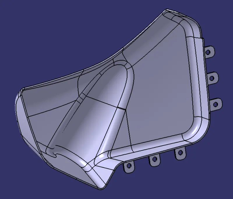
- Flanges are created using master sections.
- Flanges are used to connect the components with each other with the help of heat stakes.
Components with B-Side Features :-
1) Door Arm Rest
2) Lower Substrate
3) Map Pocket
4) Bottle Holder
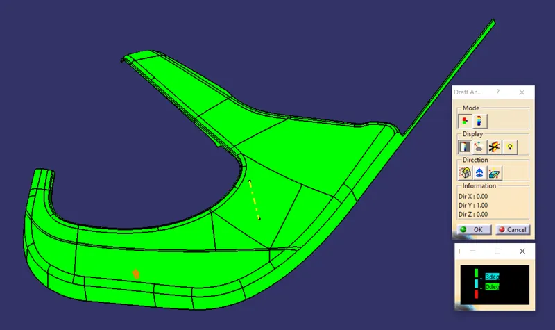
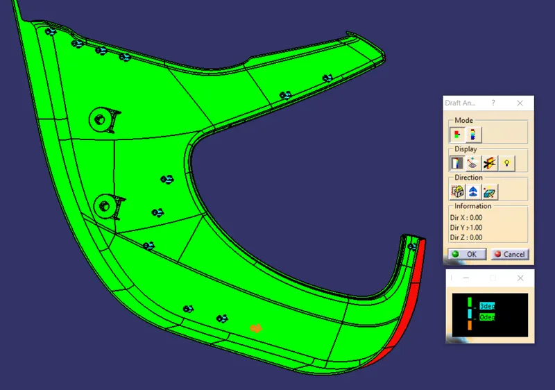
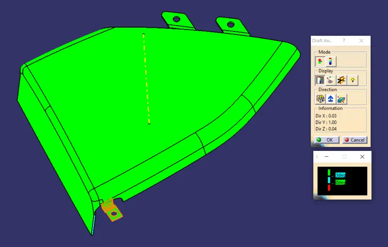
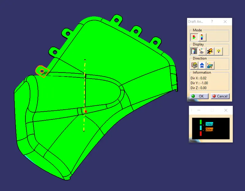
Draft Analysis :-
Draft angles are tapers on part faces that help them eject from the mold properly. They are calculated as a degree measurement from the vertical axis of a mold, and they help account for the fact that injection molded parts shrink as they cool.
Without a draft angle, parts are more likely to stick to the mold and warp or break when they’re removed. Draft angles help reduce friction between the finished part and the side of the mold.
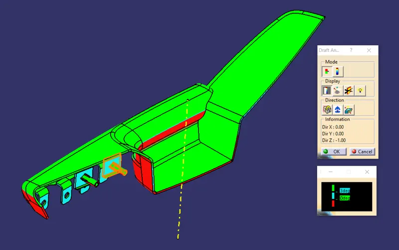
Draft analysis is performed based on colour ranges identifying zones on the analyzed element where the deviation from the draft direction at any point, corresponds to specified values. Minimum draft angle is considered as 3 degree.
1) Door Arm Rest :-
2) Lower Substrate :-
3) Map Pocket :-
4) Bottle Holder :-
Final Assembly :-
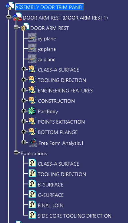
Tree Structure :-
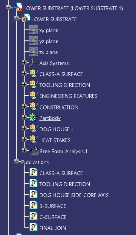
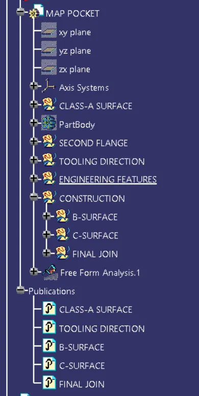
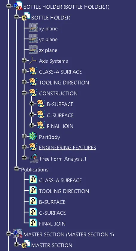
Views of Assembly
Front View :-
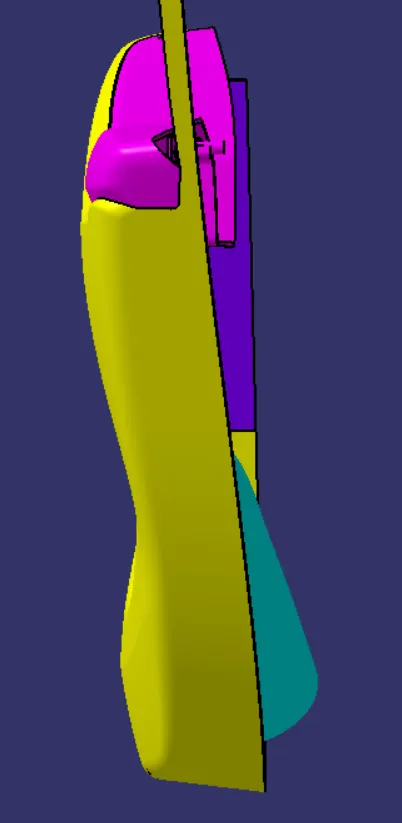
Top View :-
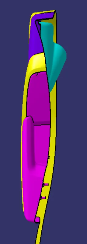
Left Side View :-
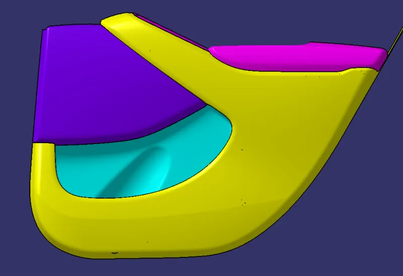
Right Side View :-
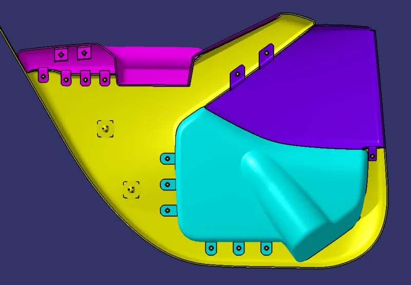
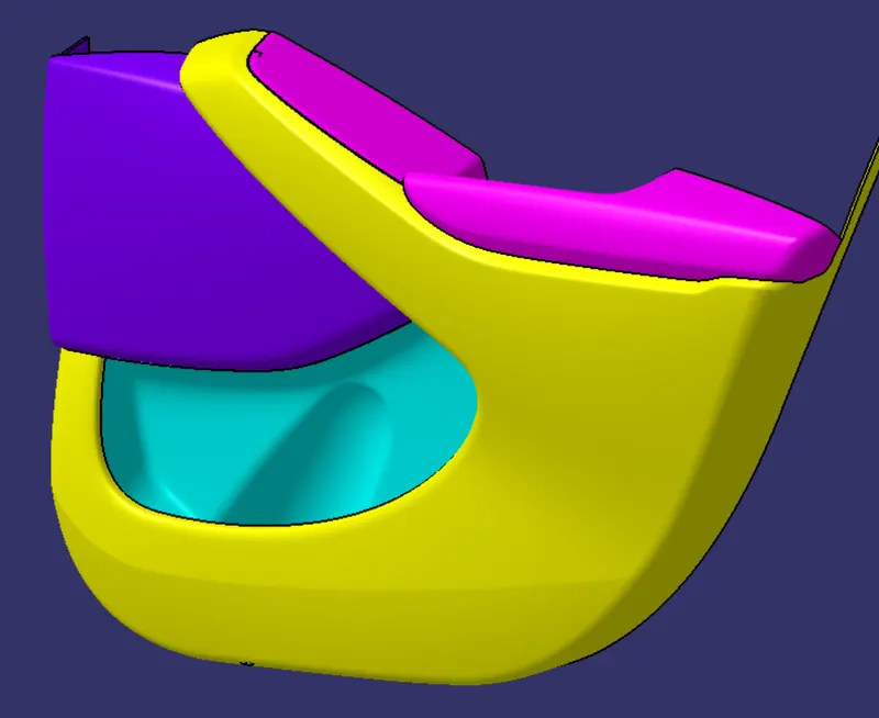
Isometric View :-
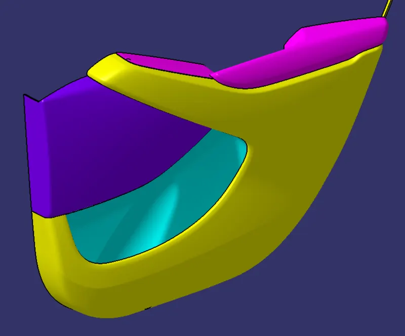
Conclusion :-
Thus the Door Trim panel with mounting features has been designed using the given class-A surface and master sections.