Week 9 - Project - A pillar Design with Master Section
Aim :- To design the A-pillar through the given Class-A surface and master section.
Objective :-
- To create a proper tooling direction.
- To perform draft analysis of the plastic component.
- To design the A-pillar plastic component by creating the B-Surface and C-Surface using the given Class-A surface.
- To create the Dog house for the A-pillar plastic component using the given master section.
Tooling Direction :-
- In Molding machine arrangement is given to open the mold along a direction which is known as Tooling Direction.
- In other words. The mold is built from two separate halves (Core and Cavity) and tooling direction basically define the direction of mold pulls apart.
- Tooling direction is known as primary direction.
- The ejection of the part from mold depends on the draft. A zero draft can result in difficult or no ejection due to shrinkage. It is recommended to add a minimum of 0.5 to 1 degree of the draft for non-textured surface & 3 to 5 degree of draft for textured surfaces.
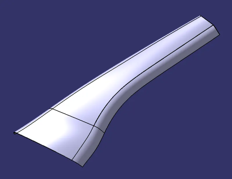
Following Class A surface is provided to design the A-pillar plastic component.
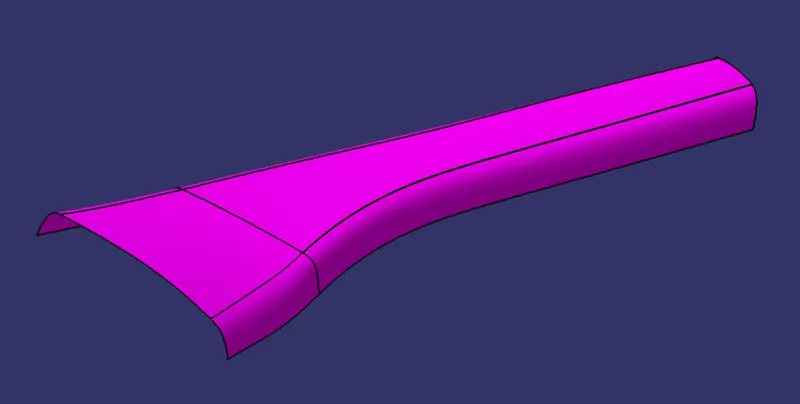
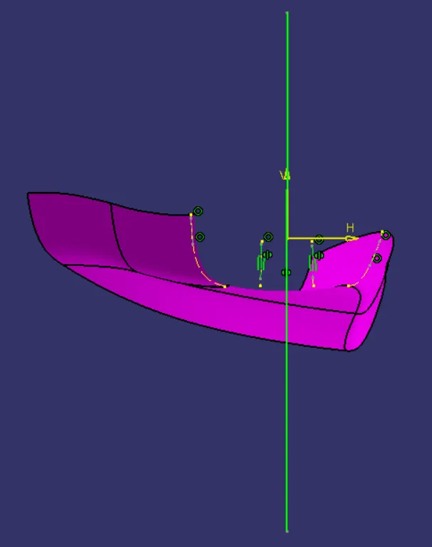
- First of all base face is extracted and point is created at the center of extracted face.
- Intersecting curves are created of Class-A surfaces.
- Lines are drawn to the side faces of the intersected curves then bisecting line is created between these two lines.
- In this way we can create the tooling direction.
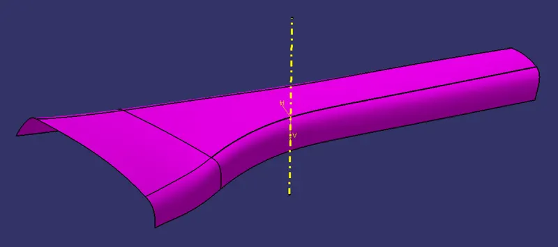
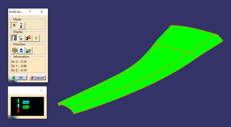
Draft Analysis of Class-A Surface :-
B-Surface :-
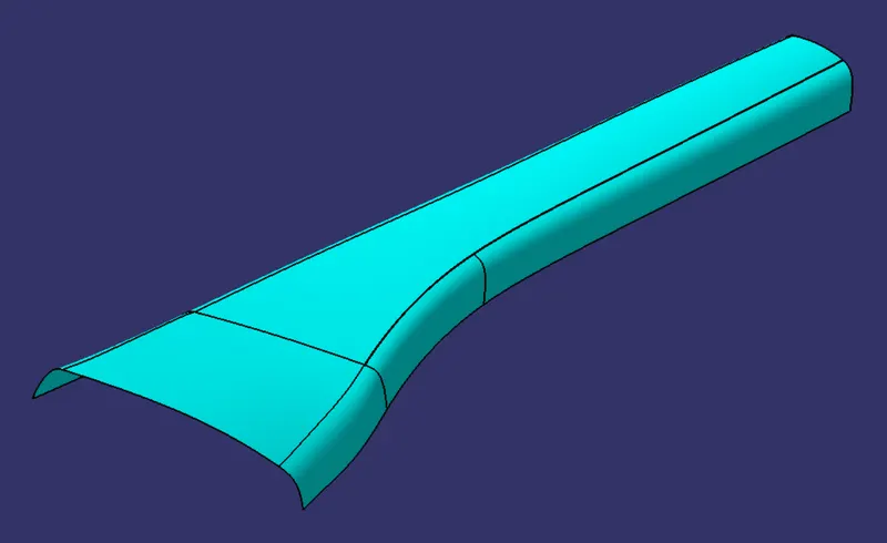
Class B-Surface is extracted from the A-surface and it is offsetted by 2.5mm in downward direction.
C-Surface :-
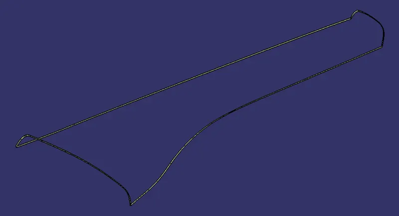
C-Surface connects the class A-Surface and B-Surface. It is created using Sweep command. Boundry of the class A-Surface is swept along the tooling direction.
Trim Surface :-
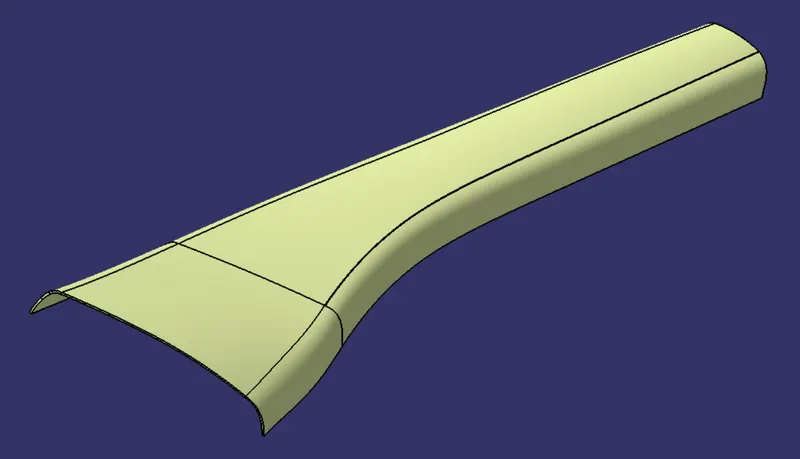
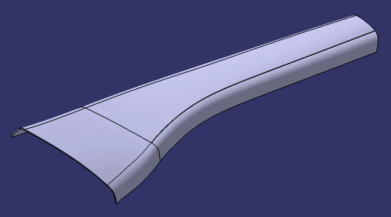
C-Surface is trimmed along the B-Surface then it is joined to the A-Surface.
Final Solid Body :-
Design of the Dog House :-
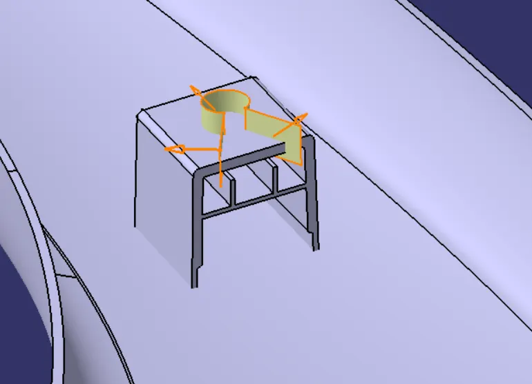
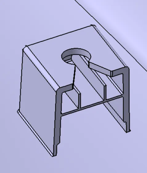
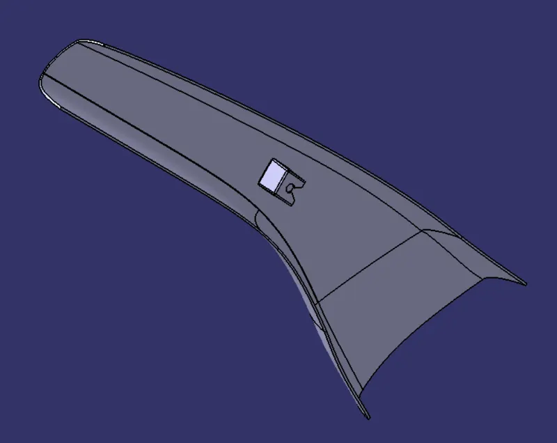
- Dog house is the feature used to avoid the sink marks.
- It gives support to the screw bosses at a specific height from the primary surface of the component.
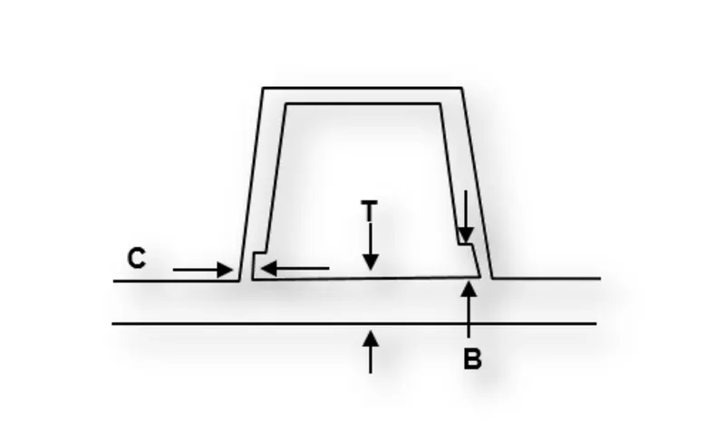
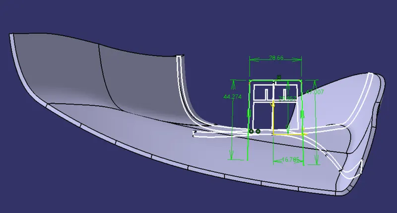
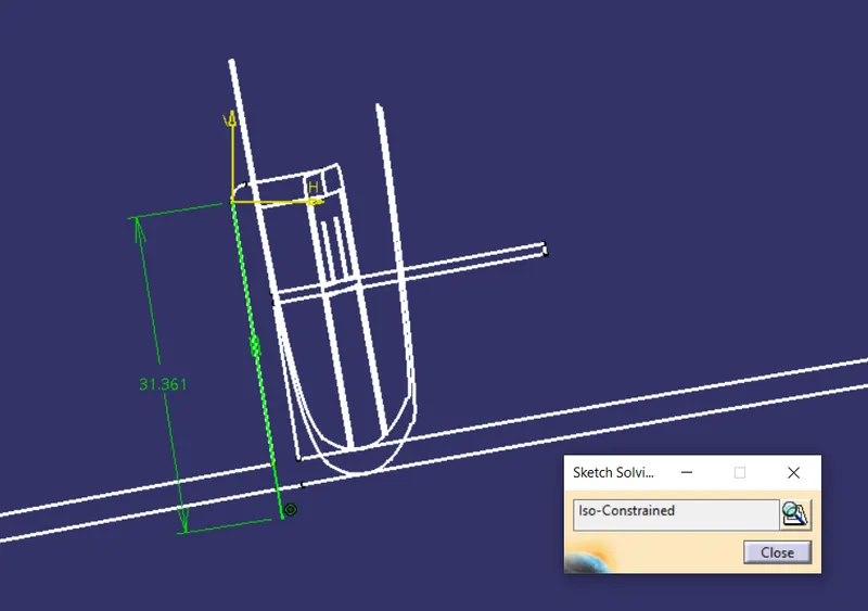
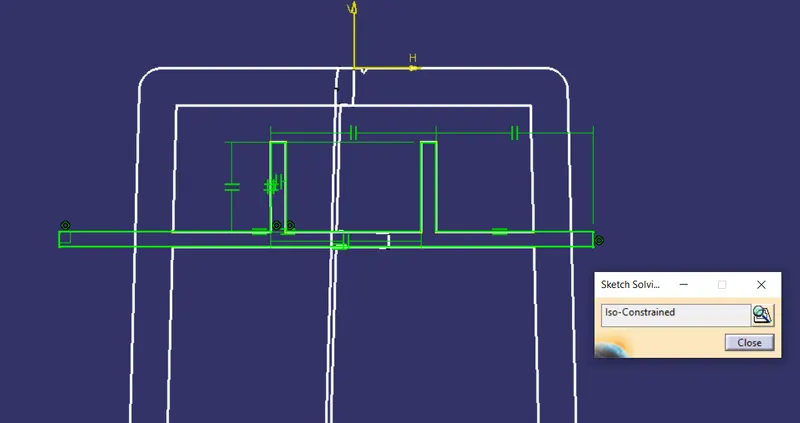
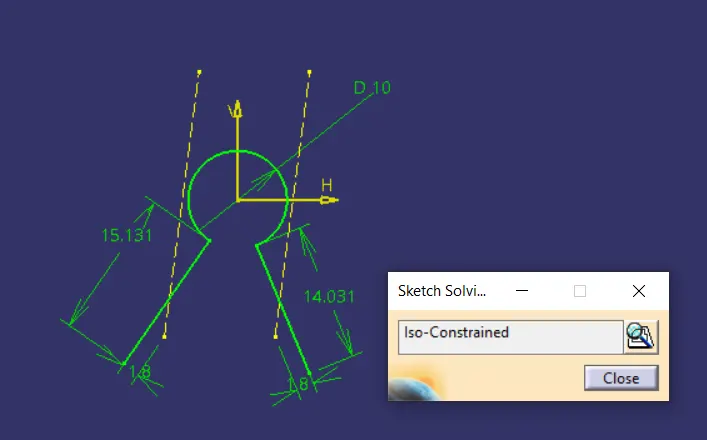
- Lines are extrcted from the master section.
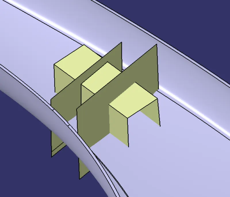
- Sketch is extruded normal to the plane.
- Similarly curves of master section are extracted from perpendicular plane.
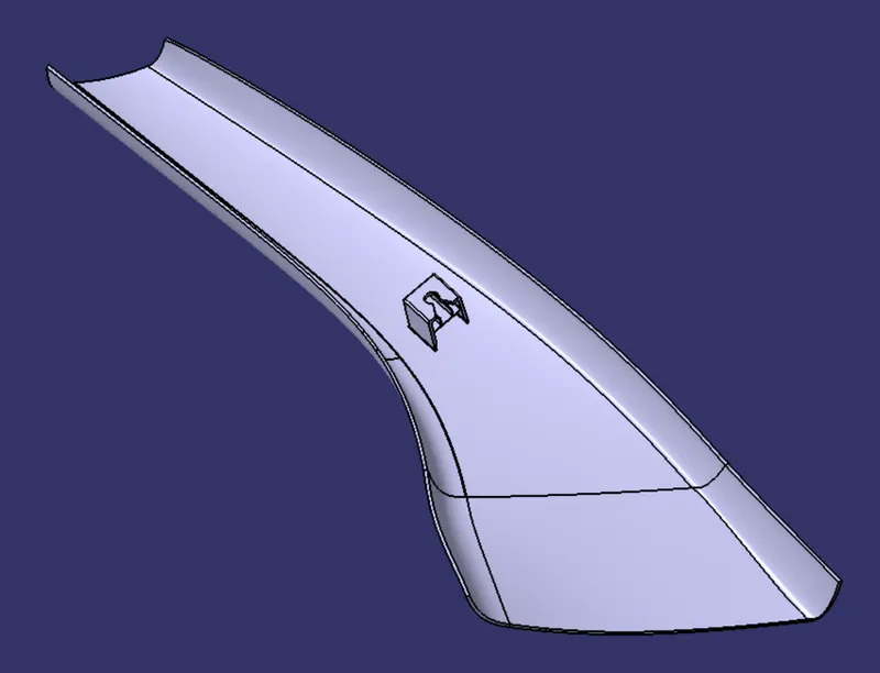
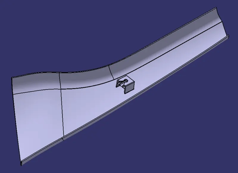
Draft Analysis :-
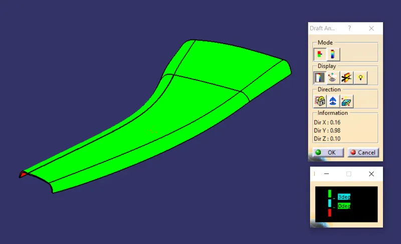
Draft angles are tapers on part faces that help them eject from the mold properly. They are calculated as a degree measurement from the vertical axis of a mold, and they help account for the fact that injection molded parts shrink as they cool.
Without a draft angle, parts are more likely to stick to the mold and warp or break when they’re removed. Draft angles help reduce friction between the finished part and the side of the mold.
Draft analysis is performed based on colour ranges identifying zones on the analyzed element where the deviation from the draft direction at any point, corresponds to specified values. Minimum draft angle is considered as 3 degree.
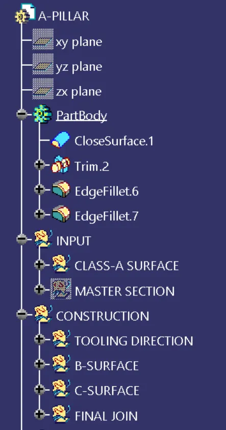
Tree Structure :-

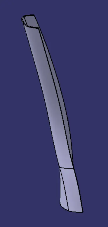
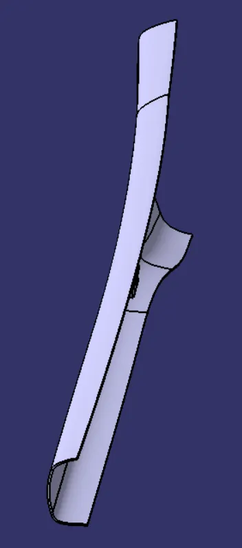
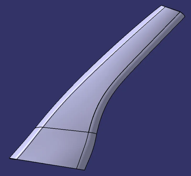
Views of Model
Front View :-
Top View :-
Left Side View :-
Isometric View :-
Conclusion :-
Thus the A-pillar has been designed using the given class-A surface and master section.