Advanced Sheet Metal Design Using NX Cad Challenge_6_Bracket
Title :- Design of sheet metal bracket using NX CAD.
Objective :- To design a sheet metal bracket using NX CAD.
Introduction :-
In mechanical engineering a bracket is any intermediate component for fixing one part to another. Brackets vary widely in shape. Sheet metal brackets are majorly used in many industries as sheet metal has low weight to thickness ratio, it is easy to transport and work with. This material is also durable and strong, which makes it ideal for a variety of applications. Its malleability is also an asset because it can be bent, cut, and formed into any shape. This quality allows fabricators to provide clients with highly specialized solutions and customized designs to meet their requirements. Another benefit of using sheet metal is its relatively low cost, which is ideal for one-off designs and also for large scale production. And lastly, this material is easy to repair, making it a practical choice for a variety of applications.
Design methodology :-
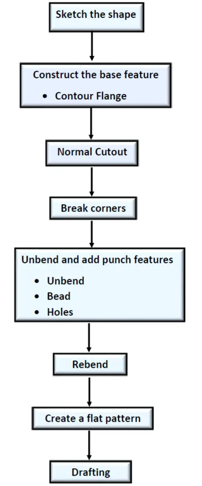
Description of Features :-
1) Sketch :- A sketch is a combination of two-dimensional (2D) entities such as lines, arcs, circles, and so on. This is used to create a basic sketch of the design on the specific plane
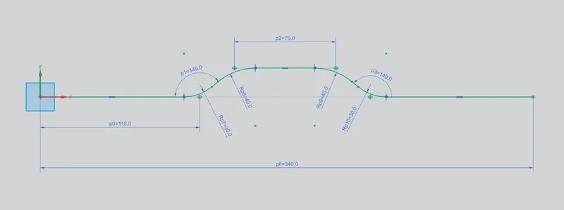
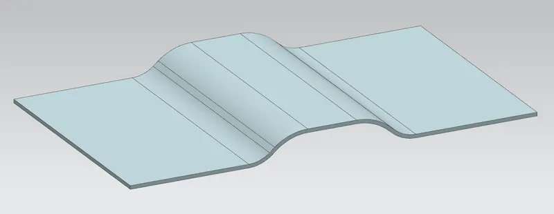
2) Contour Flange :- It creates a base feature by extruding a sketch along a vector or adds material by sweeping a sketch along an edge or chain of edges. Width of 200mm is provided to the contour flange.
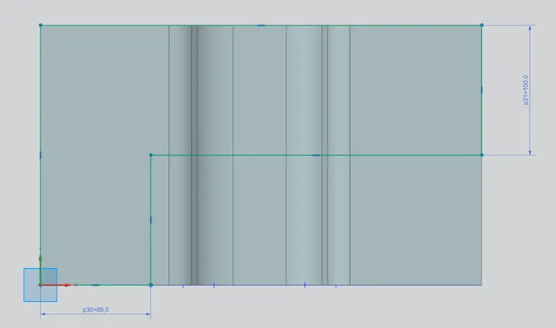
3) Normal Cutout :- It is used to cut the material by projecting sketch onto the model and then cutting perpendicular to the faces intersected by the projection.
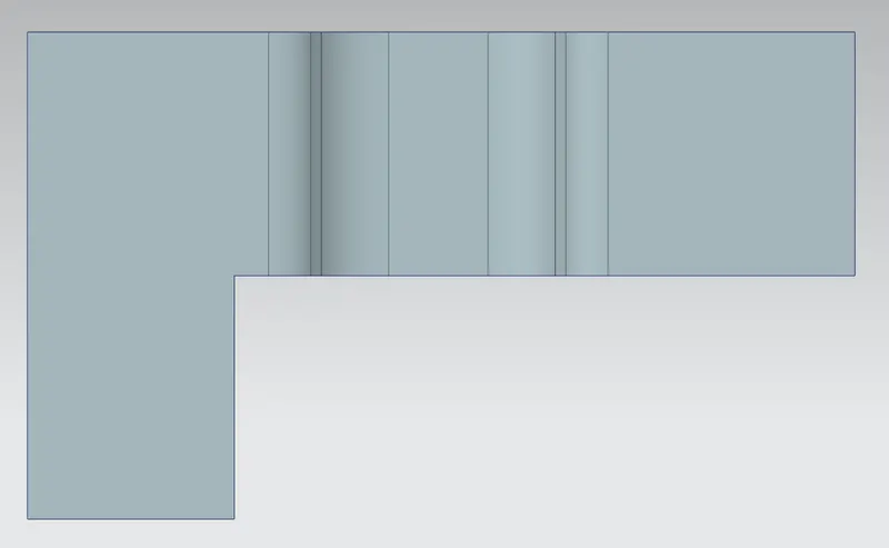
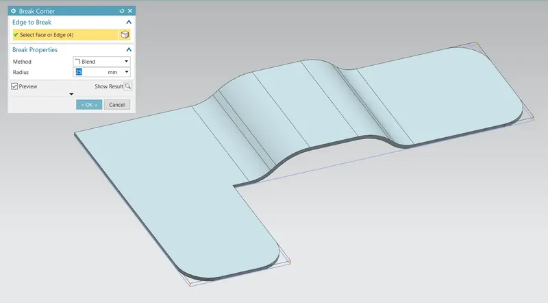
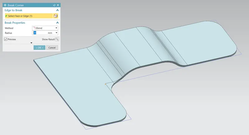
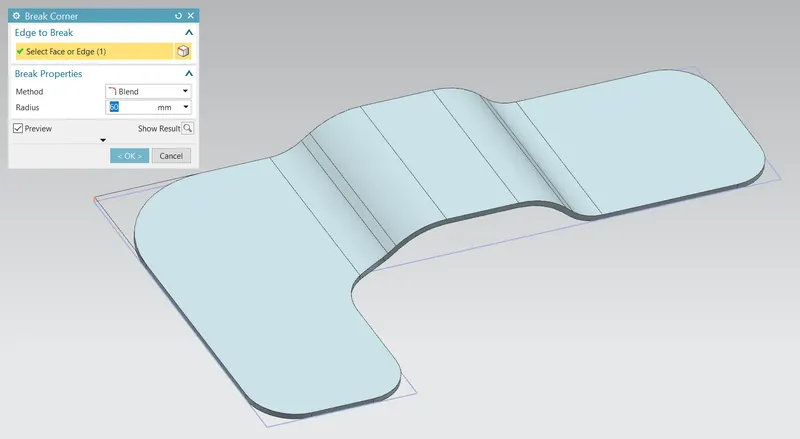
4) Break Corner :- It is used to rounds or chamfers a sharp corner of a tab or flange.
5) Unbend :- It is used to flatten a bend and the material adjacent to the bend.
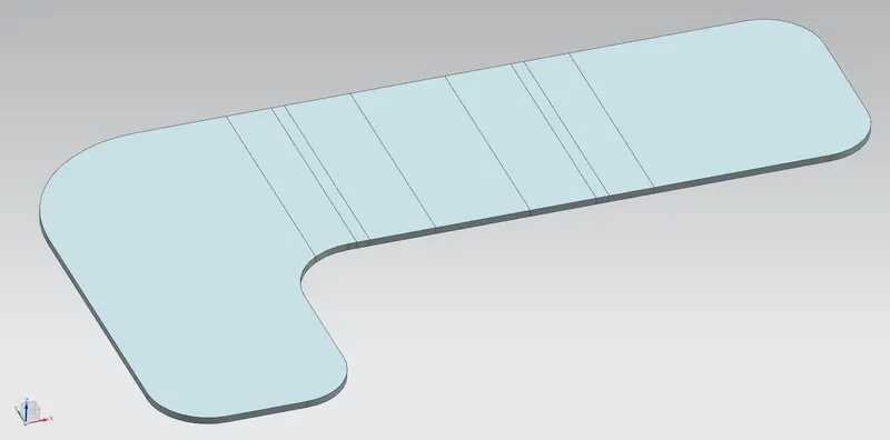
6) Bead :- It is used to lift the material along the contour of a sketch that simulates a stamping tool.
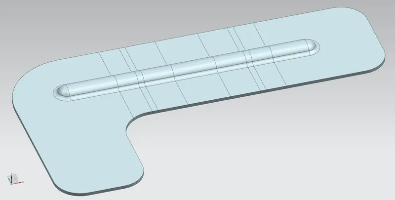
7) Rebend :- It is used to restore an unbend features to its previous bent state, along with any features added after the unbend feature.
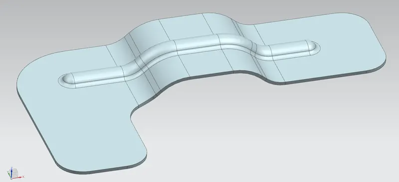
8) Hole :- It is used to add holes to one or more solid bodies. In this design simple holes with 20mm diameter is used.
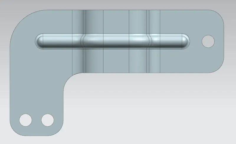
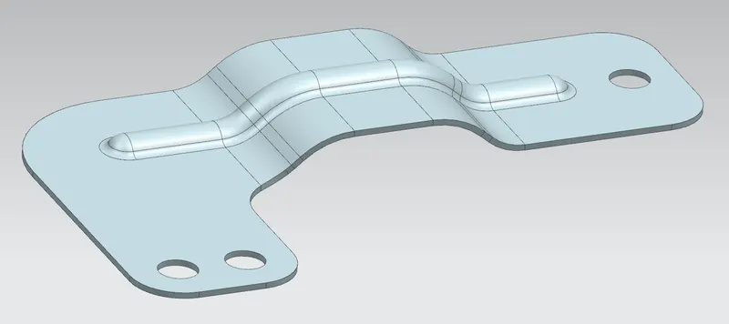
9) Flat pattern :- It creates a flat pattern feature from the formed sheet metal part.
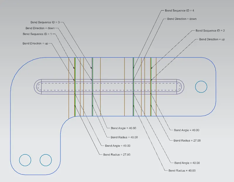
Different Views of Bracket
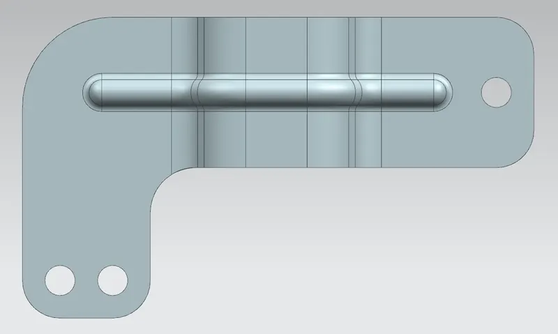
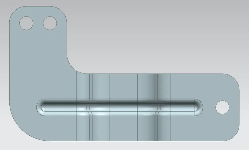
Top View :-
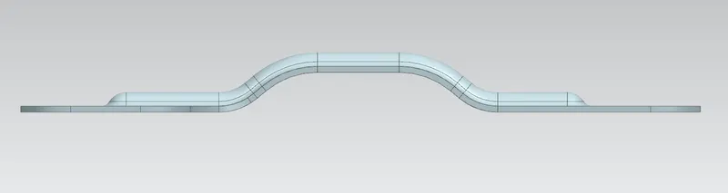
Front View :-
Bottom View :-
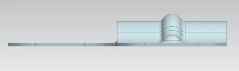
Right Side View :-
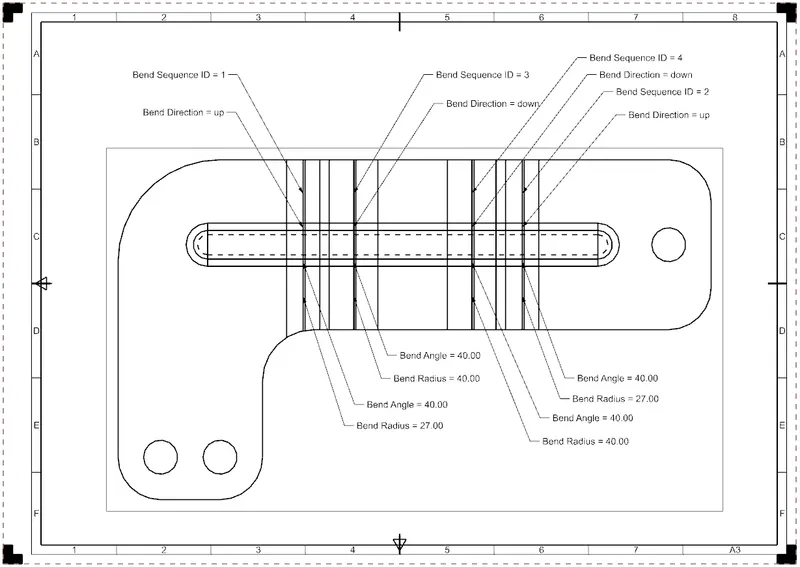
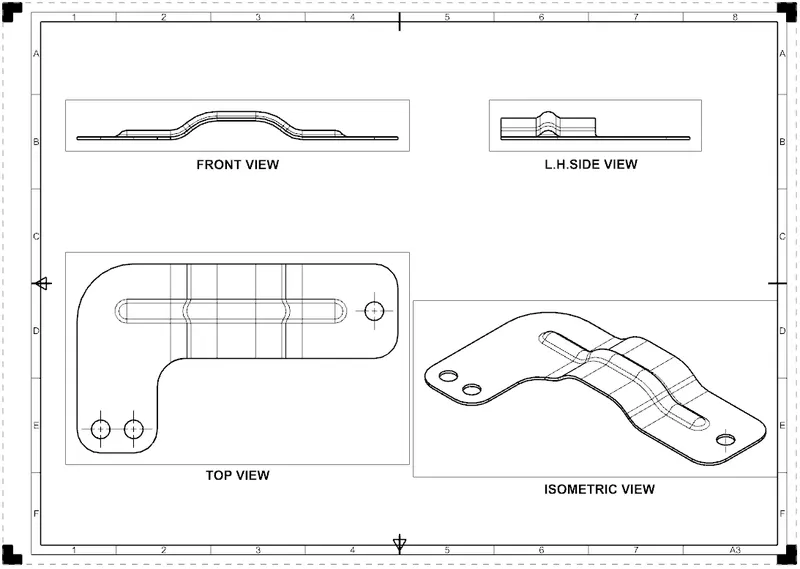
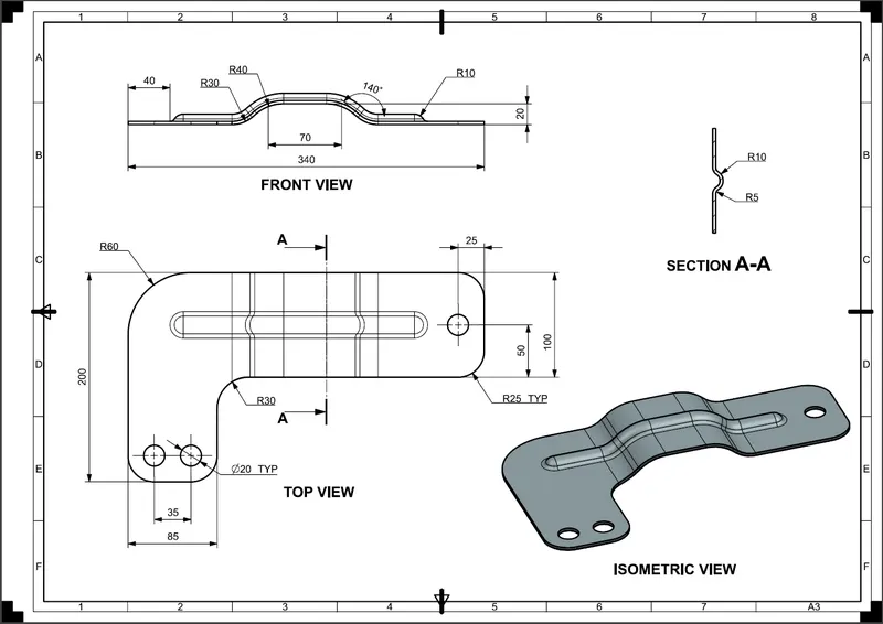
Drawing Sheets :-
Drafting application is used to create the drawings of designed model.
Conclusion :-
Thus the sheet metal bracket has been designed using NX CAD.