Advanced Sheet Metal Design Using NX Cad Challenge_1_Casing Design
Title :- Advanced sheet metal design of casing
Objective :- To design a sheet metal model of the casing using NX CAD tool.
Introduction :-
The term “sheet metal” refers to any metal that can be formed into flat pieces of varying thicknesses. Sheet metal is metal formed by an industrial process into thin, flat pieces. Sheet metal is one of the fundamental forms used in metalworking, and it can be cut and bent into a variety of shapes. Countless everyday objects are fabricated from sheet metal. Extremely thin sheet metal (thickness less than 0.3mm) is considered foil or sheet, and pieces thicker than 6 mm (0.25 inch) are considered plate steel or “structural steel”.
Metals used in the sheet metal industry include cold rolled steel, mild steel, stainless steel, tin, nickel, titanium, aluminium, brass, and copper.
Sheet metal is used in automobile and truck (lorry) bodies, major appliances, airplane fuselages and wings, tinplate for tin cans, roofing for buildings (architecture), and many other applications. Sheet metal of iron and other materials with high magnetic permeability, also known as laminated steel cores, has applications in transformers and electric machines.
Design methodology :-
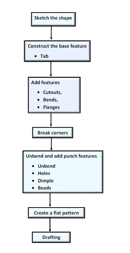
Description of features :-
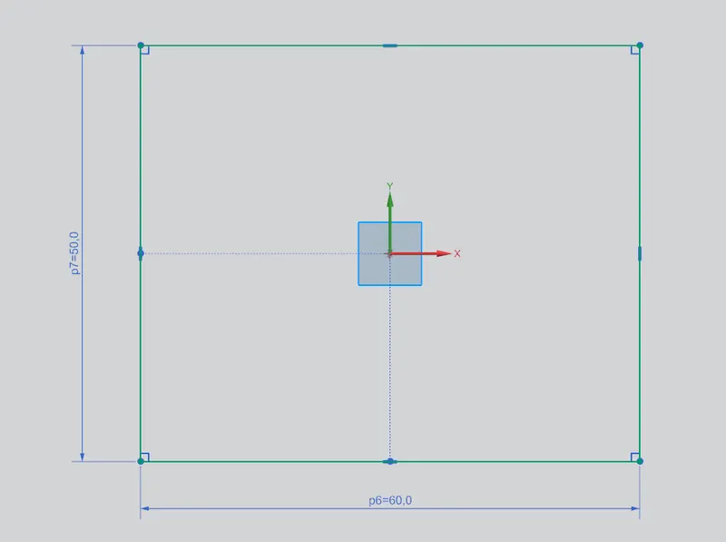
1) Sketch :- A sketch is a combination of two-dimensional (2D) entities such as lines, arcs, circles, and so on. This is used to create a basic sketch of the design on the specific plane.
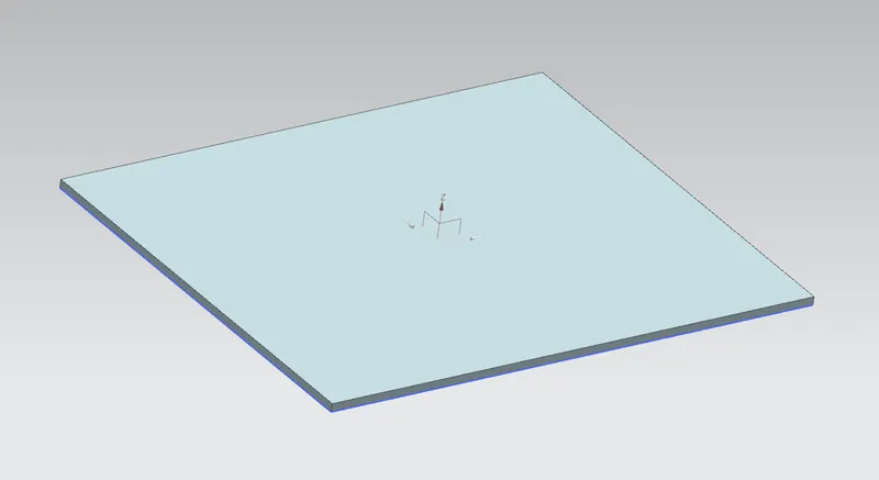
2) Tab :- It is used to create a base feature by extruding a sketch along a vector by a thickness value or adds material to a planar face.
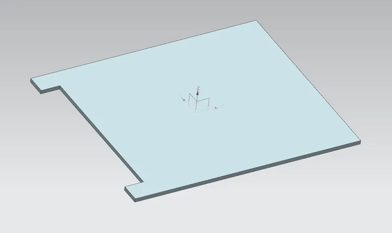
3) Normal cutout :- It is used to cut the material by projecting sketch onto the model and then cutting perpendicular to the faces intersected by the projection.
4) Bend :- It is used to modify the model by bending material on one side of a sketch line.
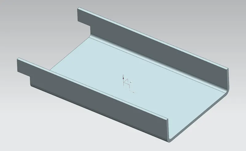
5) Flange :- This command is used to add a flat flange at an angle to a planar face and adds a bend between the two.
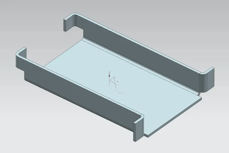
6) Break corner :- It is used to rounds or chamfers a sharp corner of a tab or flange.
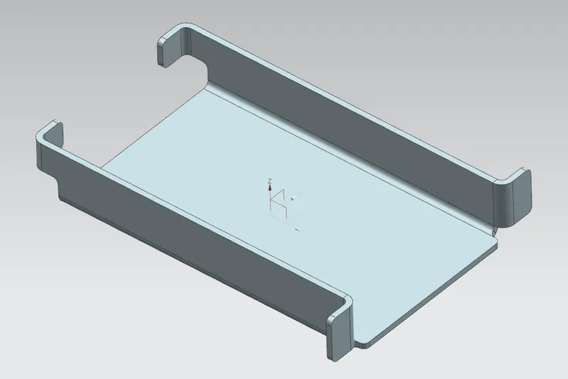
7) Unbend :- It is used to flatten a bend and the material adjacent to the bend.
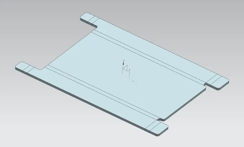
8) Hole :- It is used to add holes to one or more solid bodies. In this design screw clearance hole with normal H13 fit is used.
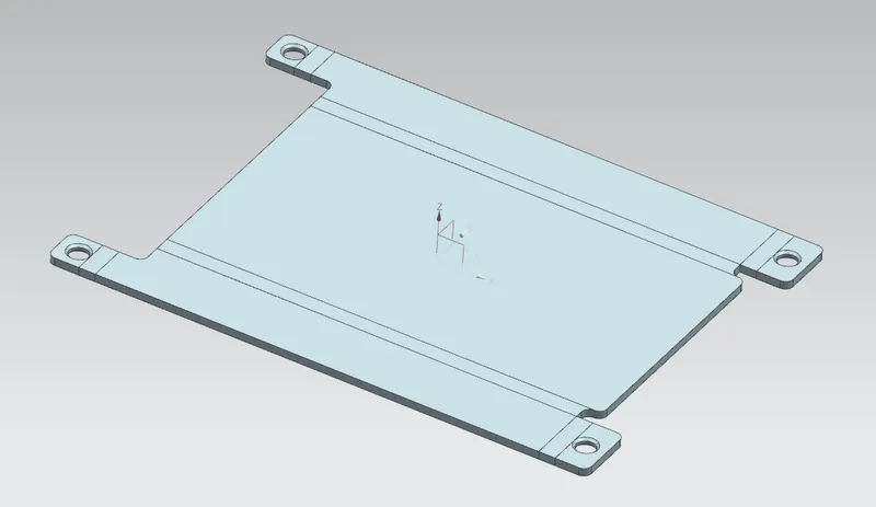
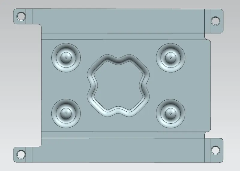
9) Dimple :- It is used to lift an area of the model inside a sketch that simulates a stamping tool.
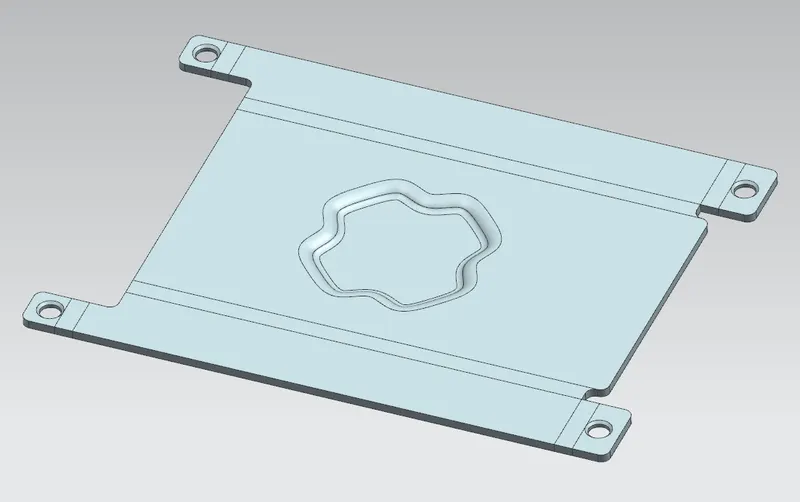
10) Bead :- It is used to lift the material along the contour of a sketch that simulates a stamping tool.
11) Rebend :- It is used to restore an unbend features to its previous bent state, along with any features added after the unbend feature.
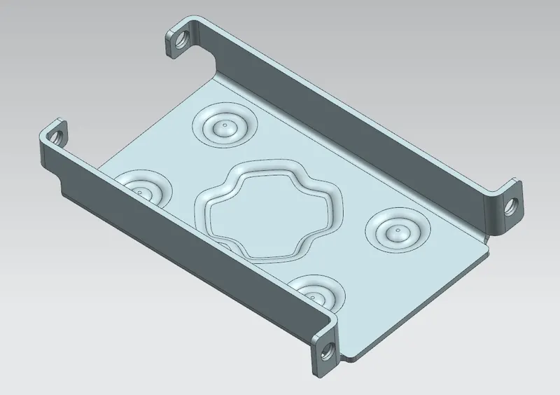
12) Flat pattern :- It creates a flat pattern feature from the formed sheet metal part.
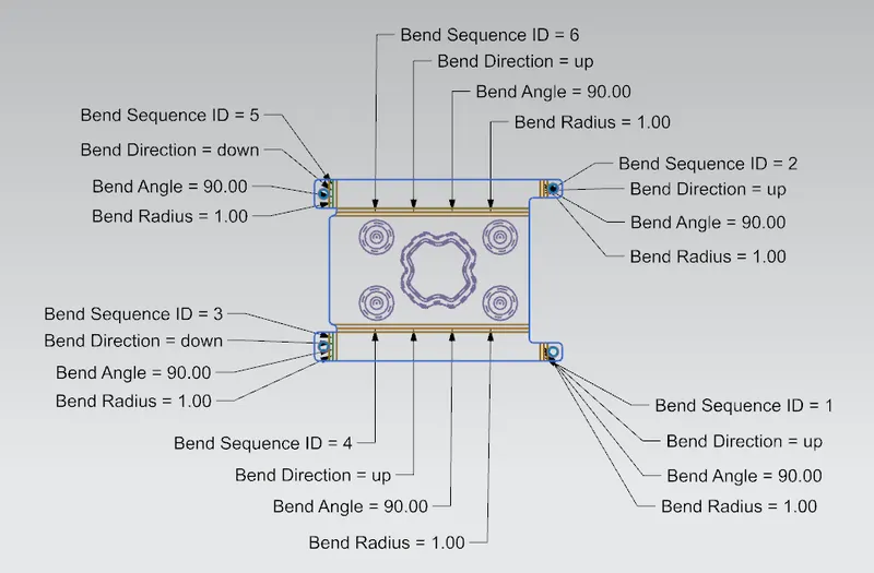
Views of Casing design :-
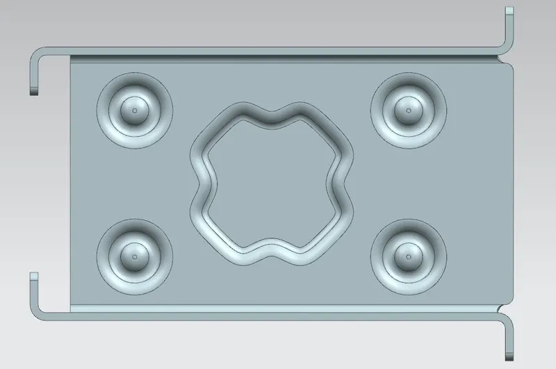
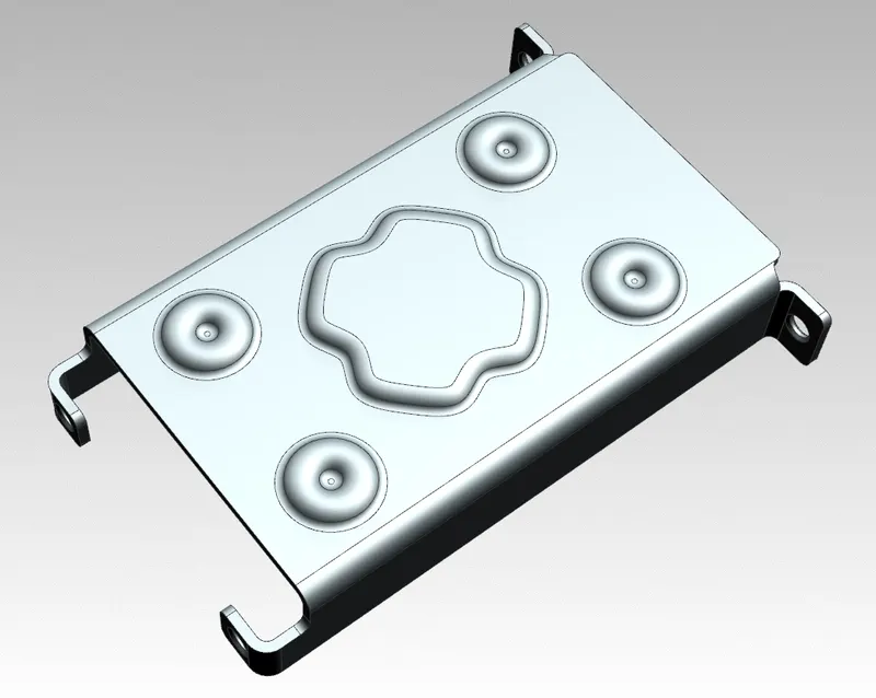
Top view
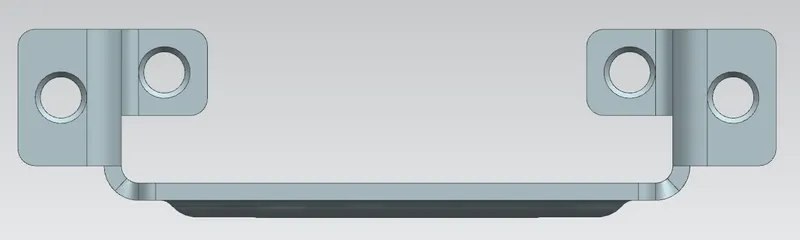
Right hand side view
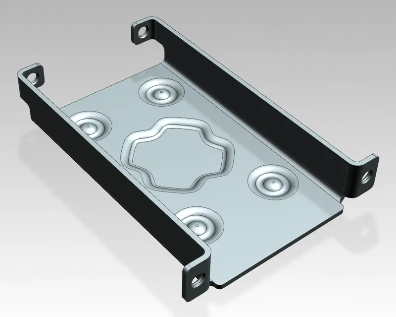
Bottom view
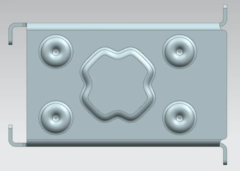
Isometric view
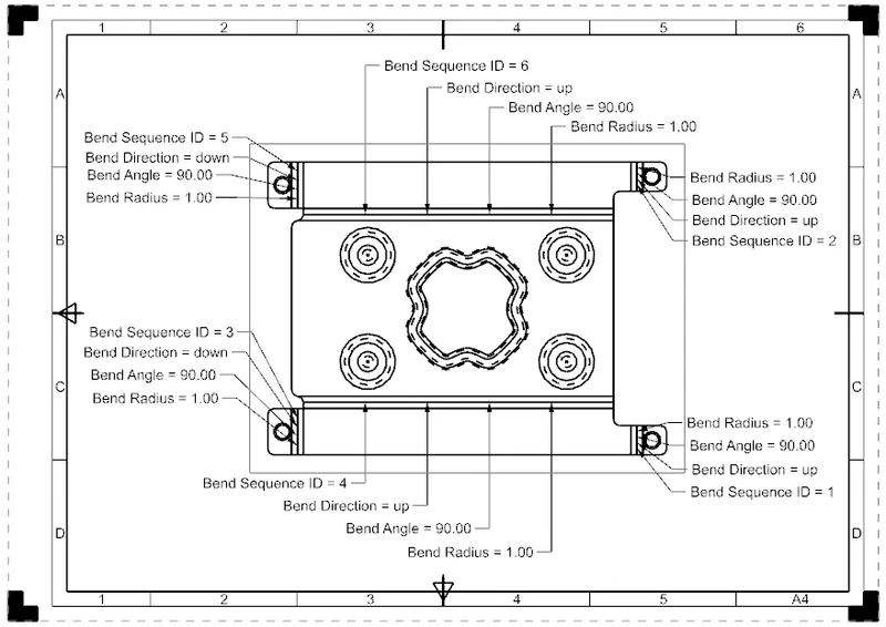
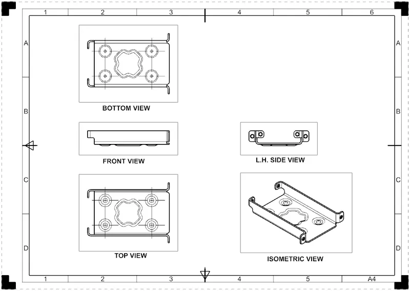
Drawing sheets :-
Drafting application is used to create the drawings of designed model.
Conclusion :-
Thus the sheet metal model of casing has been designed and gained knowledge about sheet metal and its applications.