Week 9:- 2D Detailing Challenge
1 - WHAT ARE THE DRAWING TEMPLATES ?
ANS -
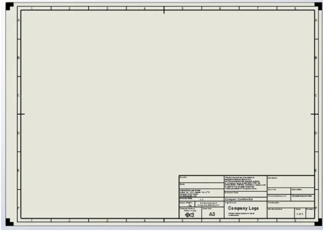
- A drawing template is basically the drawing standards as per the customer specification .
- Drawing template is a format which is used show the detailing of different parts or unit in fixture.
- It gives detailed information like angle of projection used for presentation , views that are to be considered , scaling of the parts in drawing etc.
- There are various details that are available in the template , and these information is very much useful for the manufacturing processes like machining finish , tolerances , surface finish , materials , name of part , name of assemblies , etc .
- It is recommended that we create a standard template for a particular project at the start as this template can be used throughout the project for drawing and detailing .
2 - WHAT DO YOU UNDERSTAND BY ANGLE OF PROJECTION ?
ANS -
- Angle of projection is a method of orthographic projection which is a technique of portraying a 3d design into its corresponding 2d views.
- It can also be defined as the angle at which the observer draws an object to convert it from 3d space into 2d views is known as angle of projection .
- It is basically the view formats to represent the orthogonal view of assemblies or parts.
- 1st and 3rd angle projection is majorily used in the automotive sectors.
- By understanding the angle of projection , it helps us to derive an actual image of 2D drawing .
- Angle of projection is also important for various manufacturing processes , machine shops etc as it gives a clear understanding about the object .
3 - WHAT IS THE FIRST ANGLE AND THIRD ABGLE PROJECTION ? AND WHY CAN'T WE USE 2ND AND 4TH ANGLE OF PROJECTION?
ANS -
a) First angle projection -
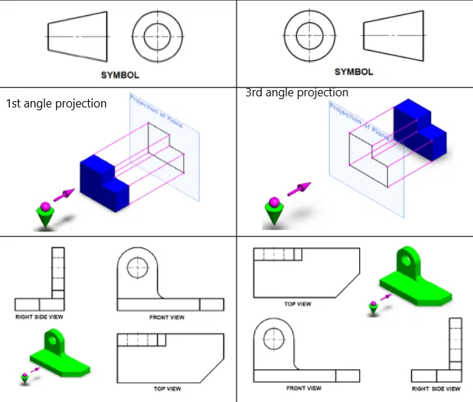
- In first angle projection , the object is assumed to be placed in 1st quadrant . the object is assumed to be placed in between projection plane and observer . the views are obtained by projecting the images on respective planes .
- In this , as the object lies between the observer and plane of projection so the plane of projection is assumed to be non transparent.
- When the views are drawn in their relative position , the top view comes below front view , right side view drawn to the left side of elevation .
- The first angle of projection is mainly used in india and european countries .
b) Third angle projection -
- In third angle projection , the object is assumed to be in 3rd quadrant. the plane is between the object and the observer . the views are obtained by projecting the images on respective planes .
- In this , as the plane lies between the observer and the object the plane of projection is assumed to be transparent.
- When the views are drawn in their relative position , the top vie comes above front view , right side view is drawn to right side of elevation.
- The third angle projection is mainly used in USA .
c) Why 2nd and 4th angle projection not used ?
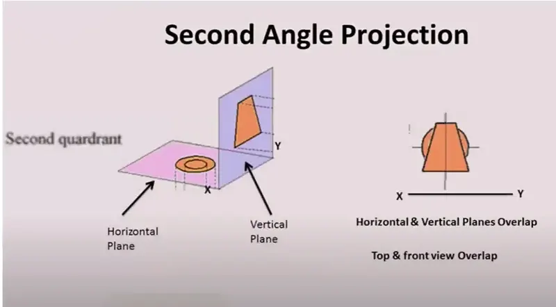
- let us consider a object is kept in 1st quadrant and 3rd quadrant, now if we will rotate the horizontal plane by 90 degree in clockwise direction as per rule , the views that we get will not be intersecting .
- But if we place the object in 2nd or 4th quadrant and we rotate the horizontal plane by 90 degree in clockwise direction then the views we obtained is self intersecting .
- The front and the top views are overlapped for the 2nd and 4th angle projection .
- this is the reason , these two projection types are not used in industry .
4 - WHAT IS GD&T ? WHAT ARE THE BENEFITS OF GD&T ?
ANS -
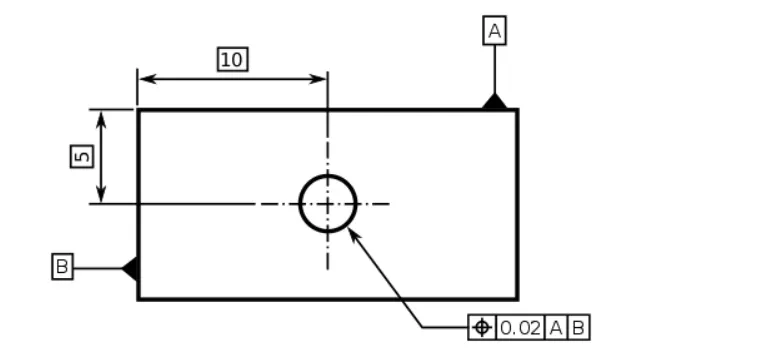
- Geometric dimensioning and tolerancing also known as GD&T is a language of symbols and standard designed and used by engineers and manufacturers to describe a product and facilitate communication between entities working together to produce something.
- It uses a symbolic language on engineering drawings and computer generated 3d models that describe its nominal geometry and allowable variation.
- It tells the manufacturing staff what degreee of acuracy and precision is needed on each contolled feature of part.
Benefits of GD&T
- It is a standarized design language .
- It is a clear way for customers , suppliers and production team to have a common language for communication.
- It enhances design accuracy by allowing appropriate tolerances that increase production.
- Clear , concise GD&T data is readily adaptable to various digital design programs , including nearly universally used 2d and 3d cad files.
- As a single consistent language , GD&T reduces guess work and interpretation while ensuring consistent geometry across design and manufacturing.
5 - EXPLAIN ALL SYMBOLS USED IN GD&T ?
ANS -
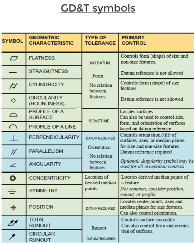
- Flatness is a symbol that determines how flat a surface is irrespective of the datum .it is helpul in showing the features which have a flat surface .
- Straightness has two different functions depending on how it is called out . in normal form or surface straightness is a tolerance that controls the form of line somewhere on the surface. and axis straightness denotes how much curve is allowed in parts axis .
- Cylindricity is symbol that is used to denote of how close a object is to a true cylinder.
- Circularity is a symbol that is used to denote of how close a object is to a true circle .
- Profile of surface is a symbol that describes a 3 dimensional tolerance zone around the surface.
- Profile of a line is a symbol that describes tolerance zone around any line in any feature.
- Perpendicularity is a symbol that controls perpendicularity between two 90 degree surfaces or features.
- Parallelism is a symbol that controls parallelism between two surface or features.
- Angularity is a symbol that describes the specific orientation of one surface to another at a referenced angle.
- Concentricity is a symbol that controls the central axis of controlled feature with datum axis
- Symmetry is a symbol that ensures two features on a part are uniform across a datum plane.
- Position or true position is the exact coordination or location defined by basic dimensions or other means that represent the nominal value .
- Total runout is a symbol that determines how much a entire feature or surface varies with respect to datum when the part is rotated around 360 degree around datum axis .
- Circular runout is a symbol that determines how much variation the feature has with the rotational axis if it is rotated by 360 degree .