Week 6:- Clamp Unit & Pin-Clamp Unit Design Challenge
CLAMP UNIT AND PIN - CLAMP UNIT DESIGN -
Product name - (P002_Z04_ST05_00_00)
OBJECTIVE - 1) Design 3 different types of swivel clamp unit with different riser , blade , clamp arm for given car panel.
2) Design a pin clamp unit for car panel .
INTRODUCTION -
Fundamental of clamp unit design -
- It is preferred to design clampunit with pivot centreline in line with the clamp surface . when possible upto 25mm offset is possible .
- For single angular clamping , it is recommended that the centreline of clamp pivot be positioned on plane that is created by surface being clamped upto 15 degree off normal pivot location can be used in extreme cases where recommended clamping condition cannot be achieved .
- There should be sufficient distance maintained between clampunit parts and the cylinder .
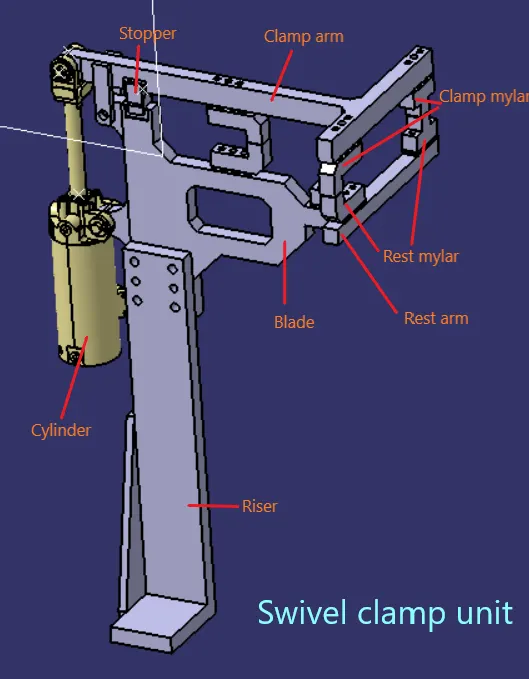
Swivel clamp unit -
- It is a unit designed to clamp or hold car panel with NC blocks/mylar/rest by using a pneumatic clamp cylinder .
- This type of clamp unit has a pivot pin around which the clamp arm rotates .
- It consist of parts like clamp arm , finger , back -up rest , shims plate , pneumatic clamp cylinder , riser , block .
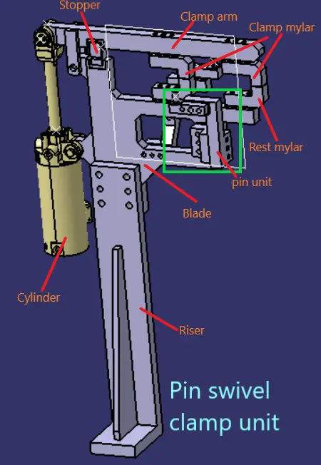
Pin swivel clamp unit -
- It is a unit of combination of pin unit and clamp unit .
- This type of unit is used in places where locating and clamping of car panel is necessary .
- A single pin or two pin units can be used to locate the workpiece and arrest the movement of car panel .
Description of parts -
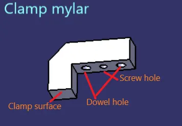
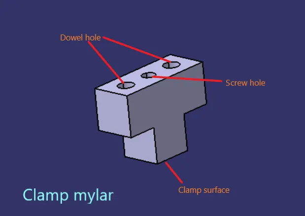
1) Clamp mylar -
- It is a NC block mounted on clamp arm of cylinder and will press car panel towards the rest mylar .
- It helps in holding the car panel firmly in postion so that the car panel does not move while the welding operarion is going on it .
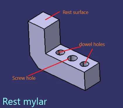
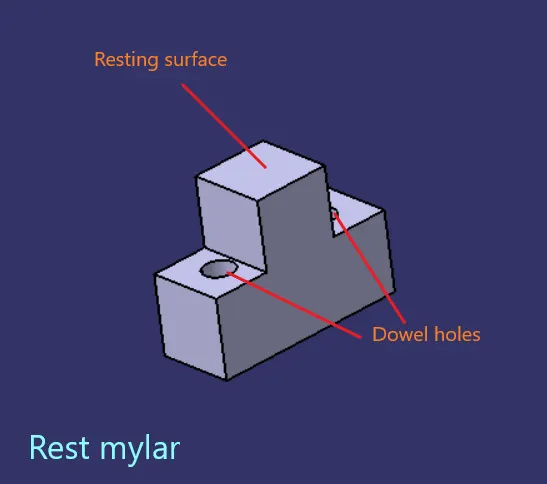
2) Rest mylar -
- It is a NC block which is fixed to the unit . on this NC block car panel will rest .
- This mylar resist the clamping force of panel . It is necessary that we should have a rest mylar where we have a clamp mylar .
3) Pin -
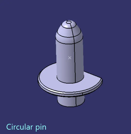
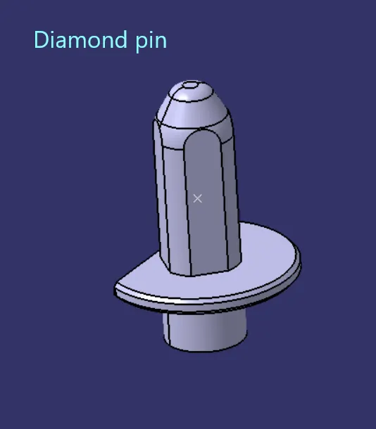
- It locates the car panel . it can either be a make part or a standard part .
- A pin should have a grinding surface on shaft with fits onto which the pin retainer is fixed .
- The mounting surface of pin should be fine machined surface .
- It should have step machine surface to lock rotation which matches with pin retainer .
- The mounting surface of pin retainer to the block should be machined surface .
- All machined planes should be perpendicular to the axis of shaft .
- Pin must have fastening provision like tapped hole from bottom or a V groove from side .
- A pin must be hardened ( heat treatment ) (55 to 60 HRC) and black oxide finished in general .
- Material - Hardened material like C45 , 16MNCR5 , 20MNCR5 , EN31 etc .
- Surface finish - black oxide , Zinc coating , Chrome plating .
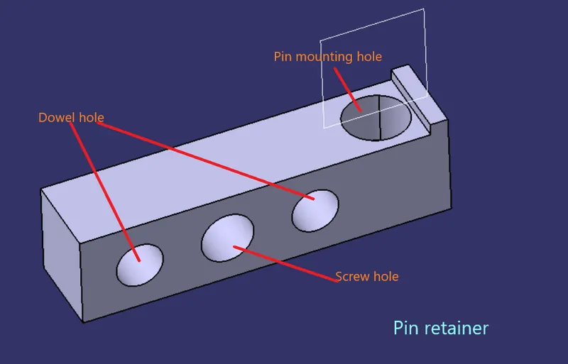
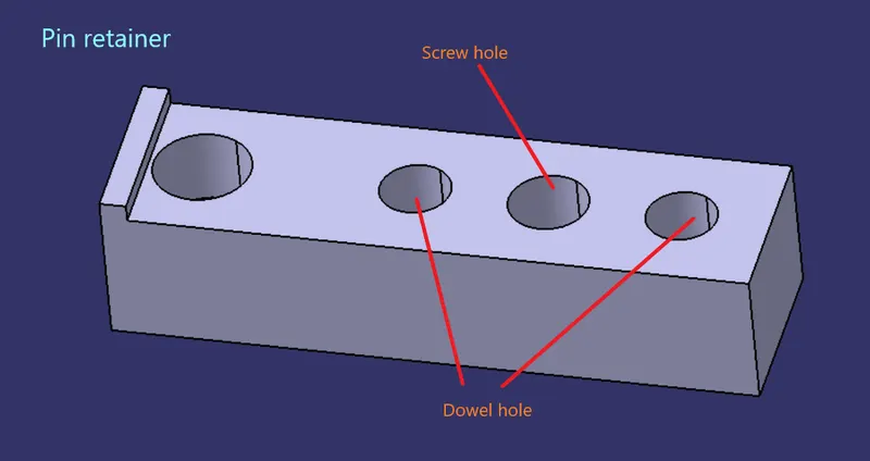
4) Pin retainer -
- It is a part which holds the pin in position , it can either be a make or a standard part .
- It should have a hole with a fit onto which pin is fixed .
- The pin mounting surface should be fine machined .
- It should have a step to lock rotation of pin .
- The mounting surface of pin retainer to block should be machined surface .
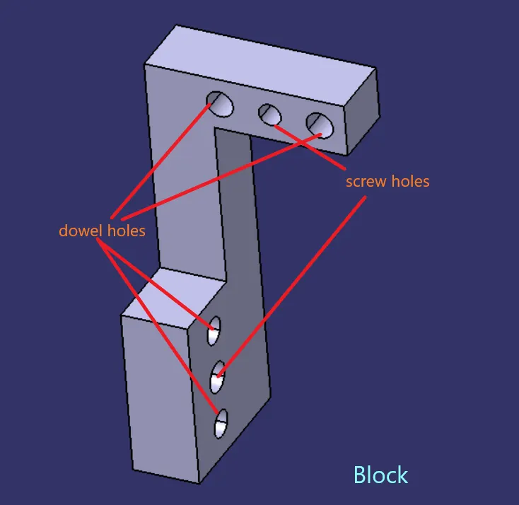
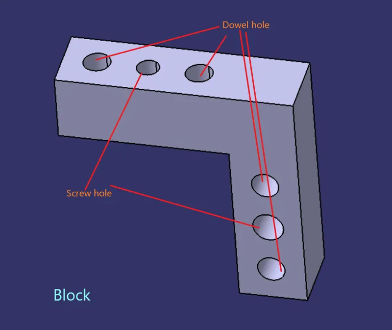
- The pin retainer will be fixed to block or a L block to riser with 2 dowel holes (pins) and atleast one screw hole to maintain tolerance .
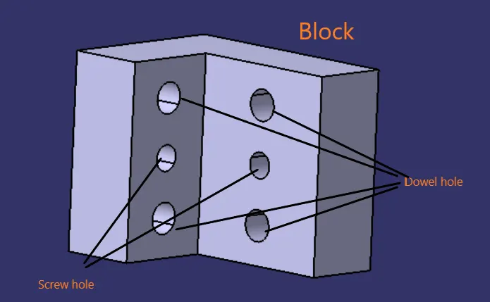
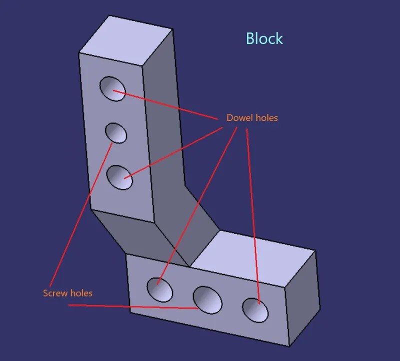
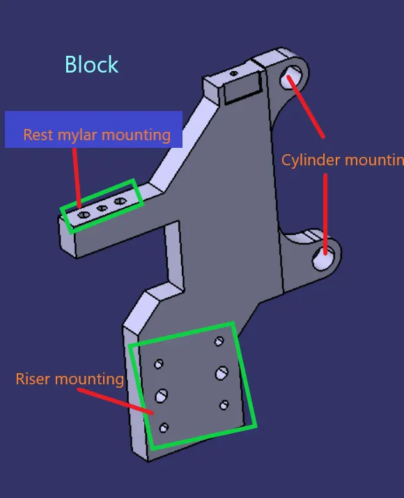
5) Blocks -
- These parts are used to accomodate the shimming direction as per fundamental in general, also in some cases used for other design feasibility .
- These blocks can be of various shape, it depends upon the parts for which we need to use the block .
6) Shims / spacer -
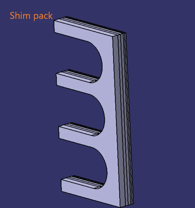
- It is a standard part in general , shims are used for adjustment of locator ( NC block and Pin retainer ) for obtaining the desired value for precise working of unit with respect to the car part .
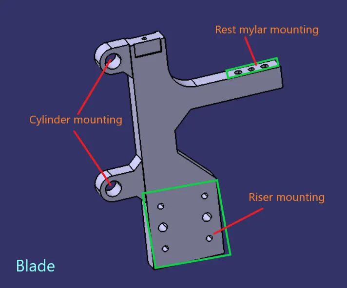
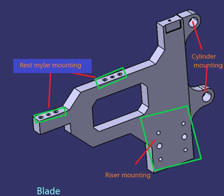
7) Blade -
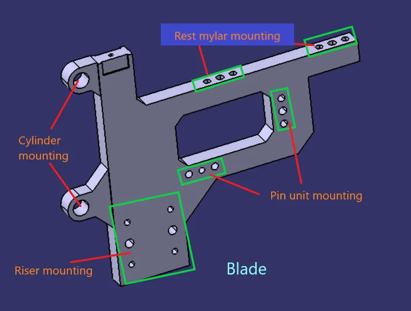
- It is like a plate which connect parts of unit to riser .
- It can be a standard part or make part .
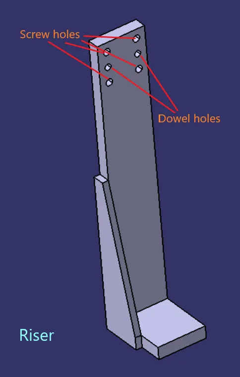
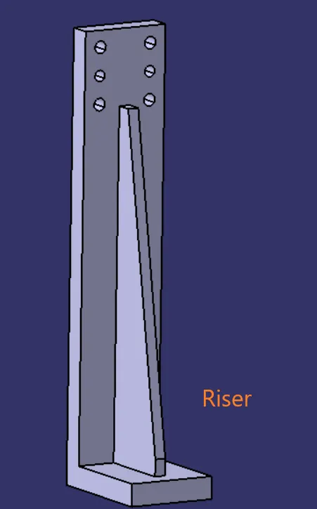
8) Riser -
- It is a part on which all parts are mounted , this riser is mounted on base plate of tool .
- In general riser is mostly a standard part , but it can be a make part also .
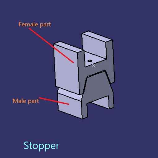
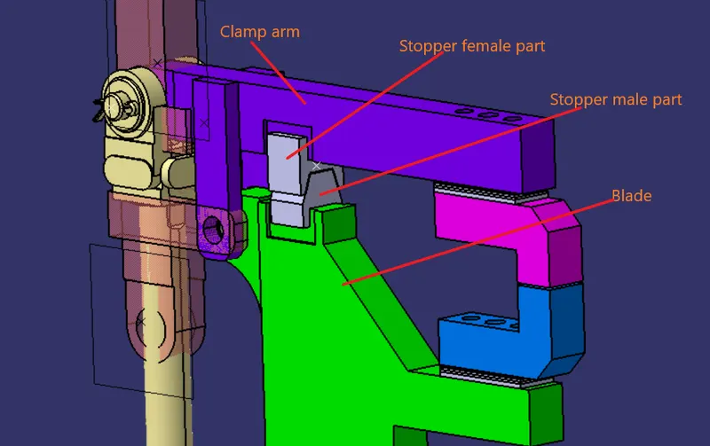
9) Stopper -
- Stopper is used in clamp unit to restrict the movement of clamp arm .
- stopper has two parts male and female part . male part is attached to the blade and female part is attached to the clamp arm .
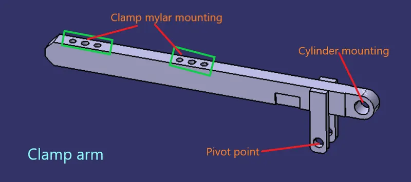
10) Clamp arm -
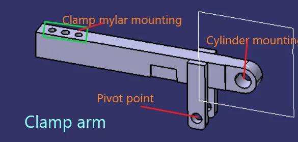
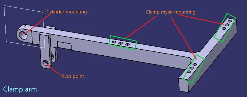
- It is a brought out part to which all the movable arms are fixed .
- It is a part of clamp cylinder .
- Clamp arm is different for different bore size of cylinder . it is also available in different hole pitch .
11) Clamp cylinder -
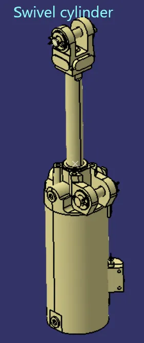
- It is a pnematic device which works with presurrised air . The clamp cylinder is used to open and close the clamp unit .
- It is a brought out part and and the manufacturers are Tunkers , Destaco , etc . it is generally available in 40 ,50 , 63 and 80 bore capacity .
- clamp cylinder opens upto 135 degree for horizontal clamping and it opens about 105 degree for vertical clamping .
- In this project we are using a clevis cylinder named CKG_1B_63_100Y .
- Here CKG stands for series of cylinder , B stands for clevis width , 63 is the bore size and 100Y is stroke of cylinder .
DESIGN METHODOLOGY -
Input -
We have received the panel as our input . we have analysed the the panel and selected the mounting points for the clamp mylars and rest mylars .
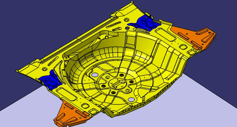
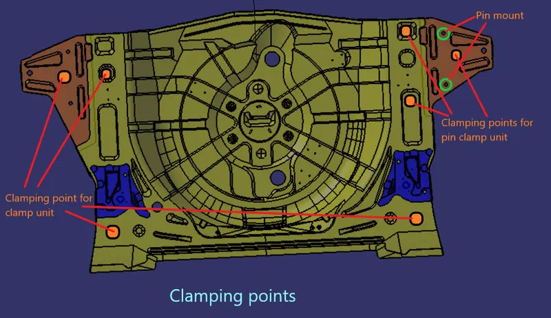
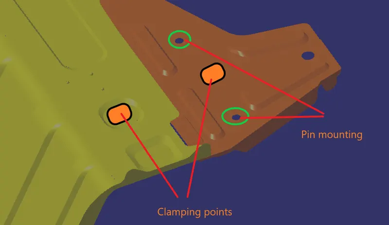
These clamping points will arrest the movement of panel in six D.O.F . moreover the two pins will arrest the the movement of panel in remaining 6 D.O.F in that area .
1) Swivel pin clamp unit -
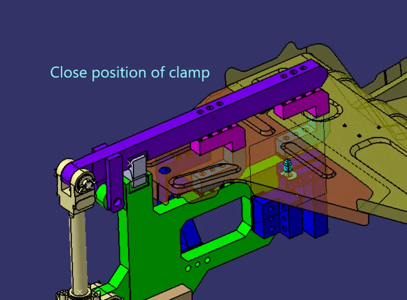
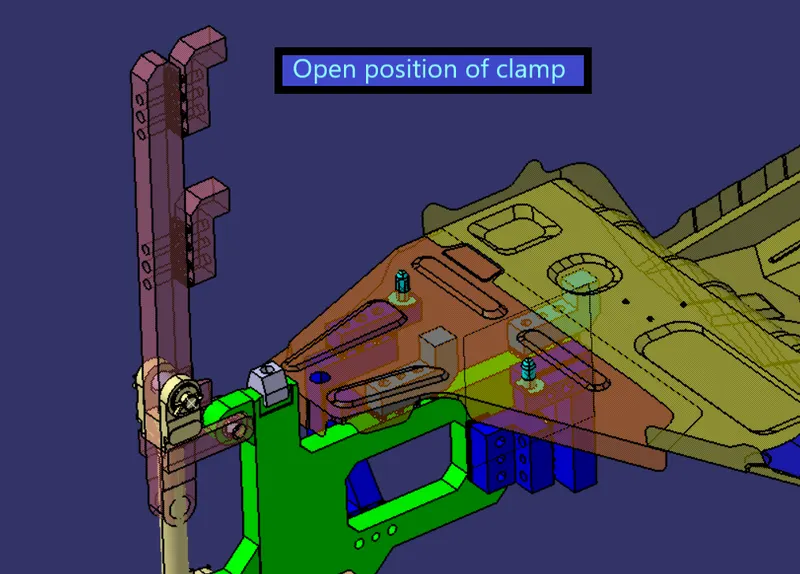
This swivel clamp unit consist of parts like clamp arm , stopper , blade , mylars , risers . in addition to this , it also consist of two pin units .one unit has circular pin and other pin unit has diamond pin . these pin units will help in location of the panel . the pin units are of fixed type .
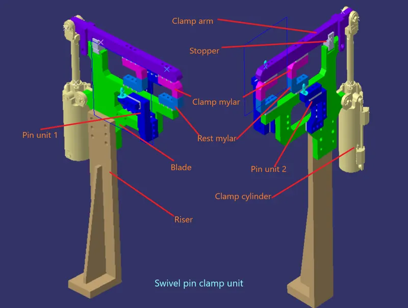
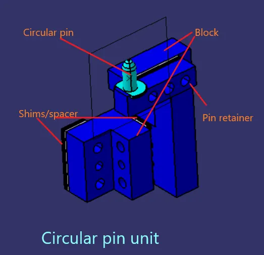
From below images we can observe the two pin units . as the holes for mounting is circular we have used one circular pin and one diamond pin . each pin unit has pin retainer and block . two way shimming is also done in the pin units .
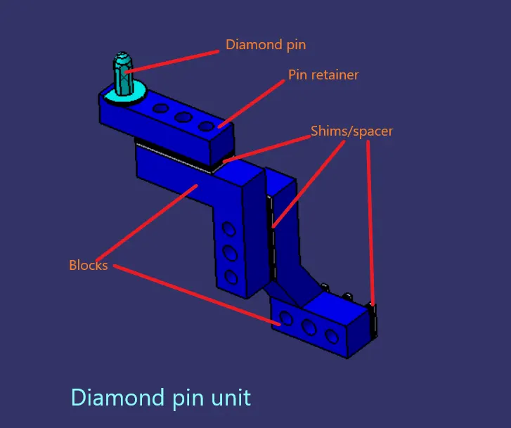
From the below images , we can see the region for which we have designed the pin clamp unit . one clamping point will be on yellow panel and one clamping point will be on orange panel . the two pins will make sure that the movement of orange panel is arrested following the 3-2-1 principle .
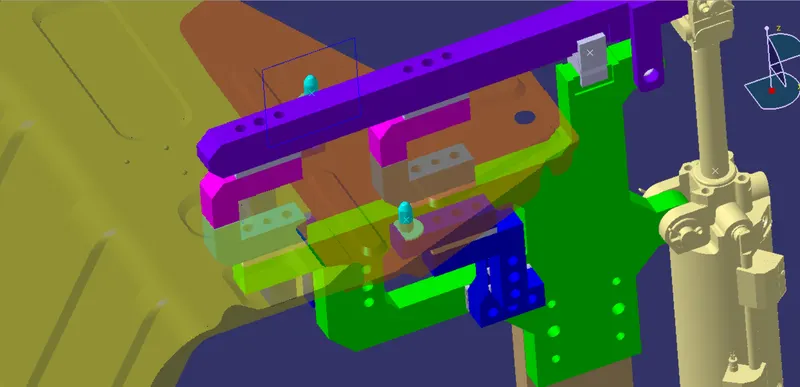
the opening and closing position of the clamp unit is shown below .
2) Swivel clamp units -
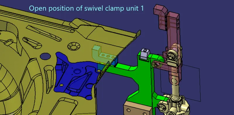
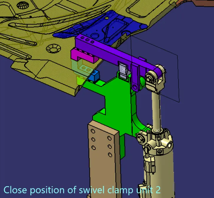
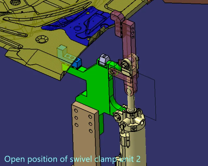
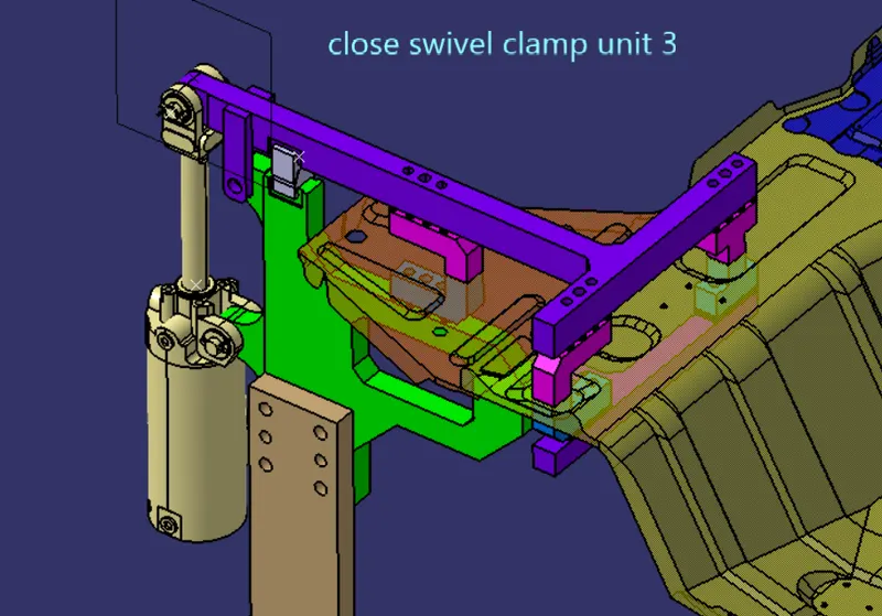
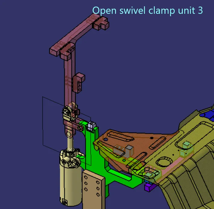
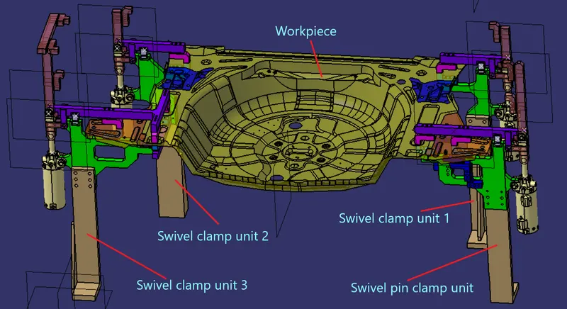
Below are the three swivel clamp units we have designed to clamp the car panel . each swivel unit consist of clamp arm, clamp mylar , rest mylar , stopper , blade , riser , shims and cylinder . shims are placed along with the clamp mylar and rest mylar .
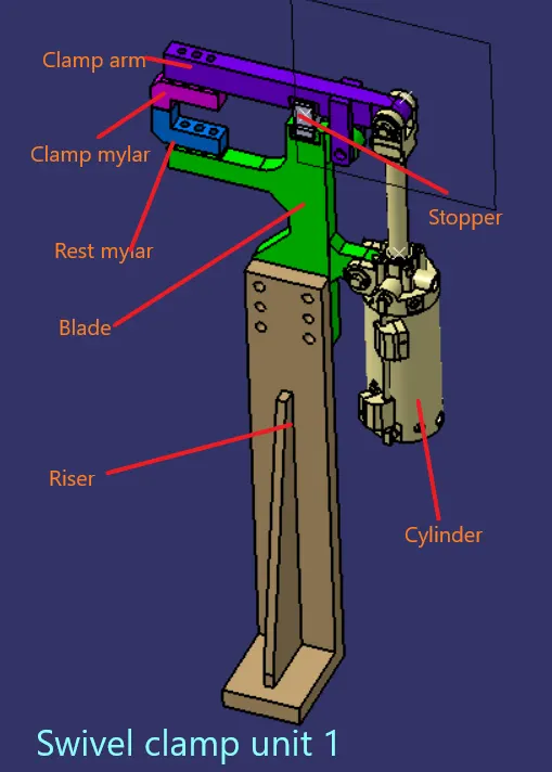
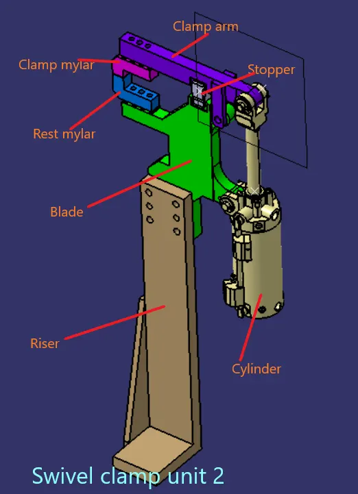
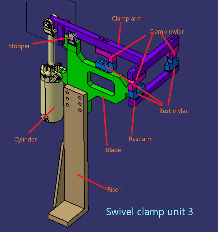
Open and close position of the swivel clamp units -
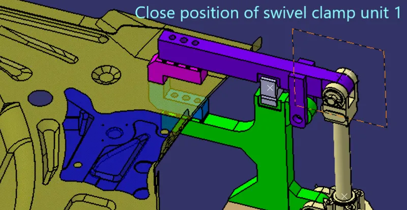
Below shown is the 3 swivel clamp units and 1 swivel pin clamp unit clamping the workpiece .
CONCLUSION -
so we have designed 3 svivel clamp units and 1 swivel pin clamp unit for the workpiece . this project was done in catia V5