Week 7- Base Unit Design Challenges 2
AIM - TO DESIGN A BASE UNIT WITH ALL THE WELDMENTS FOR THE GIVEN CAR PANEL AND TO DESIGN THE REMAINING UNITS REQUIRED FOR THE FIXTURE ASSEMBLY .
INTRODUCTION & THEORY -
BASE UNIT -
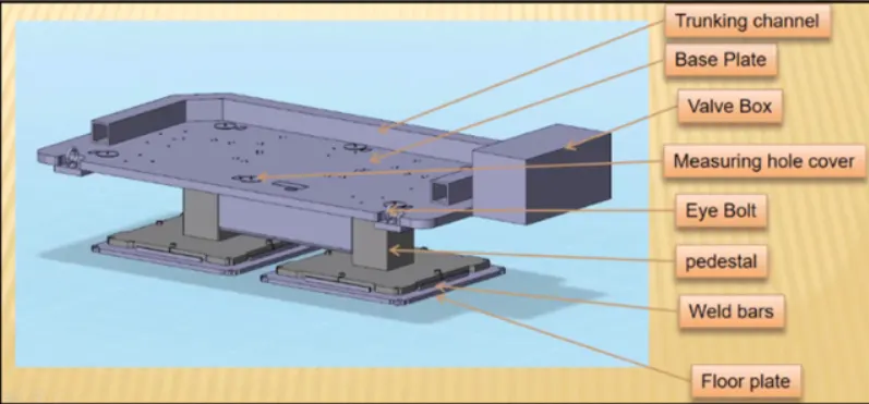
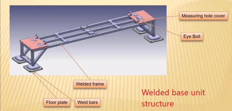
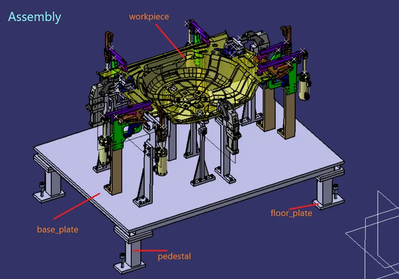
- A base unit is a unit on which all other units of the tool and other necessary parts of the tools like trunking channel , valvebox , eyebolt etc are assembled .
- Holes will be drilled on the base plate to mount all the necessary units of the tool on it .
- Base unit is an important unit in fixture assembly as it mounts all the units on it , so the base unit should be designed such that it can take up the load and absorb all the vibrations during the welding operation .
Parts of base unit -
a) Base plate -
- A base plate is a machined plate with thickness of 20 - 40 mm thickness .
- A base plate has holes drilled on it so that all the units can be mounted on it .
b) Pedestal -
- Pedestal is a part which connects base plate to the floor plate .
- It is a standard part in general and in some cases it can be welded frame integrated with base plate.
- A standard pedestal can be of different height and size.
- Depending on size of base plate , the number of pedestal varies for load distribution .
c) Trunking channel -
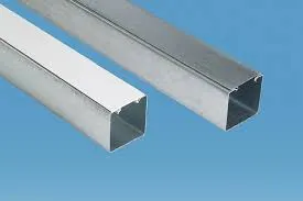
- It is a duct which accomodates all the electrical and pneumatic hoses and wires for the unit of tool .
- Trunking channel is available in different thickness and different sizes .
d) Valve box -
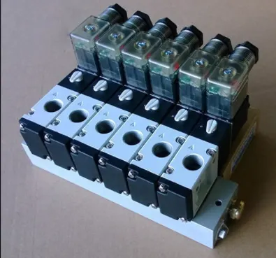
- It is a standard part which contains all the valves for the units.
- It supplies air to the pneumatic cylinders in the assembly .
- Valve box consist of solenoid valve which is used for air supply.
e) Eye bolt -
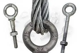
- Eyebolt is a part which is attached to the base unit , it is used for transportatiion purpose of tool.
- Lifting hooks will be used to lift the base unit or the entire tool .
- Forklift holes will also be provided in case of transportation purpose.
f) Floor plate -
- Floor plate also known as foundation plate is grounted to the floor with fixed bolt on the ground .
- A clearance of 10mm is provided between pedestal and floor plate .
- weld bars are used to weld position permanently after levelling is done .
Points that are needed to be taken into consideration while designing base unit -
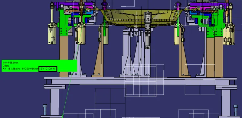
a) Working height - the working height of the base unit is an important consideration . the working height depends upon the type of welding operation like manual welding or robotic welding . for manual welding , the overall height of total tool should be 850-1100 mm in general . the working height also vary from country to country .
b) The dimension and the specification of base plate is also an important factor .below is the fundamentals given for base plate.
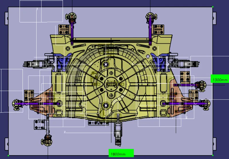
Fundamental of base plate -
- A base plate size should cover all the units with its outer periphery including the opening
- A base plate is preferred to be designed with respect to body coordinate system (b.c.s) .
- A base plate should be drilled with datum holes / measuring holes in line with the pitch with 1000 mm in general .
- Number of datum holes depend on size of the plate , a minimum of 4 holes is required .
- Datum holes should be drilled a nominal values of coordinate and in terms of 50mm and 100mm in general . ex -x200,y100,z300 .
- Datum holes should be drilled with dia 100 mm away from other units .
- Datum holes should be covered with datum plates .
c) Depending upon the units and their overall weight , we can decide if we want to use simple base unit or a welded structure base unit .
d) The base unit should be parallel to the ground , for this a height adjusting mechanism should also be provided .
e) For lifting and transportation of base unit , eyebolts should be provided , the size and number of eyebolts depend upon the base unit size .
DESIGNING UNITS FOR THE PANEL -
Input
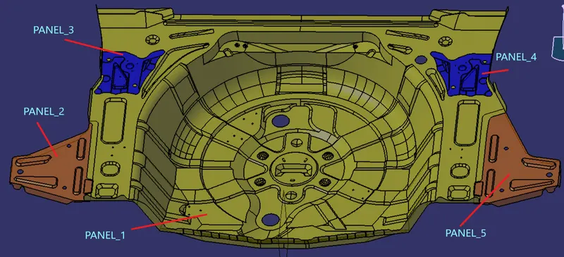
We have received the above part as our input , here we have total of 5 panels. we have to design units for these 5 panels such that all these panels cannot be moved during the welding operation . hence by using 3-2-1 principle we need to locate , and clamp the panels properly .
Panel_1 -
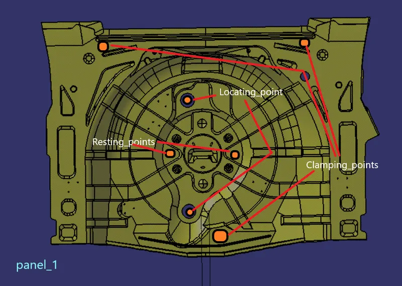
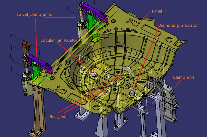
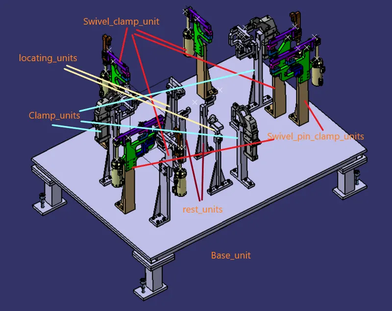
So for the panel_1 we have used two locating pins , one circular pin and one diamond pin . these two pins will restrict the movement of the panel in 4 translational and 2 rotational motions . the rest of the motions will be restricted by the three power clamps that we have provided . since the yellow panel is big in size we have also provided two rest units .
panel_2 -
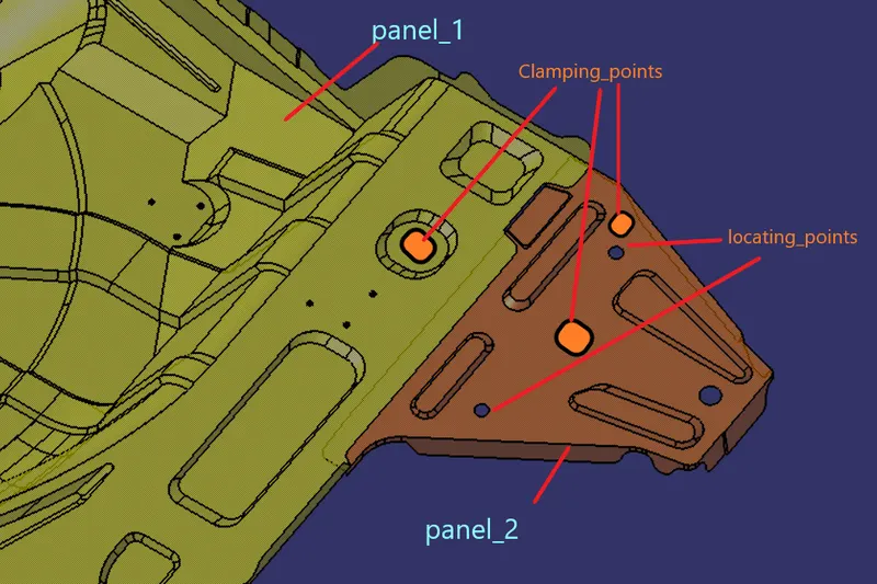
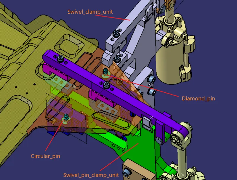
So for the 2nd panel , we will be using two locating pins , one circular and one diamond , and we will use two clamp units to clamp the orange panel in two places . so we have restricted the motion of 2nd panel in 12 D.O.F .
panel_3 and panel_4 -
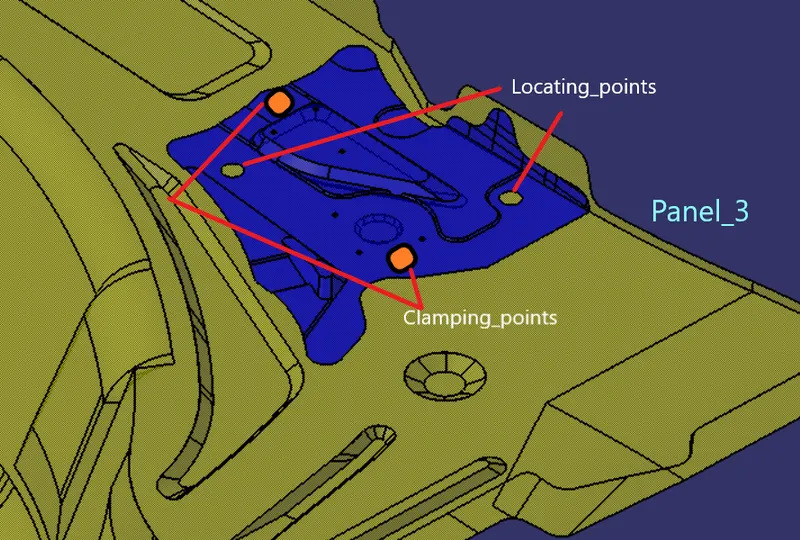
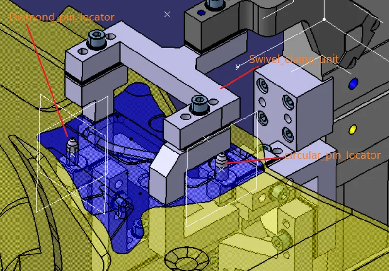
So as for panel_3 we have used 2 locating pins to locate the panel , and two clamping points . so by 3-2-1 principle , we have located and clamped the panel such that it will not move during the operation . aspanel_3 and panel_4 is a symmetric panel , we have used the same locating and clamping points over there .
panel_5 -
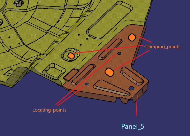
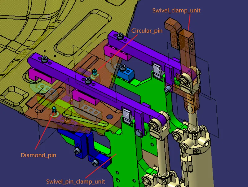
panel_5 is somewhat symmetric to panel_2 , so we have used the same locating points to restrict motion in 6 d.o.f . the other 6 d.o.f will be arrested by the two clamp units . so by applying 3-2-1 principle for all the panels , we have constructed units and made sure that the panels will not move during welding operation .
Assembly of units -
Structuring of design tree -
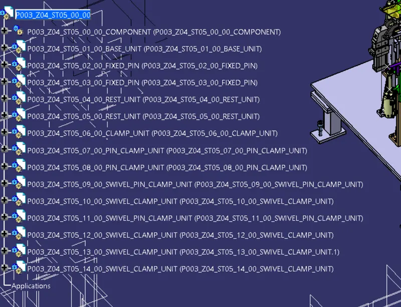
structuring a design tree is an important aspect in design as it show which parts belong to which assemblies , thier identification, their property etc . this helps to avoid errors during design study , manufacturing , assembly , inspection etc. customers provide a specific standard by which we have to name the design tree .
in our case -
P003 - project 3
Z04- zone 4
ST05- station 5
00 - unit number
00 - part number .
CONCLUSION -
We have designed a base unit for our project and we have also designed the other necessary units to locate and clamp the panels using 3-2-1 principle restricting their D.O.F