Advanced Sheet Metal Design Using NX Cad Challenge_1_Casing Design
TITLE - CASING DESIGN USING NX-CAD.
OBJECTIVE - To create a casing using sheetmetal workbench tools following all the design rules and parameters in used sheetmetal .
INTRODUCTION - Nx cad software is a simple and powerful tool which has wide variety of application in various industries such as automobile , medical , aircraft etc . using the sheetmetal workbench from nx , we will create the required part . .
DESIGN METHODOLOGY -
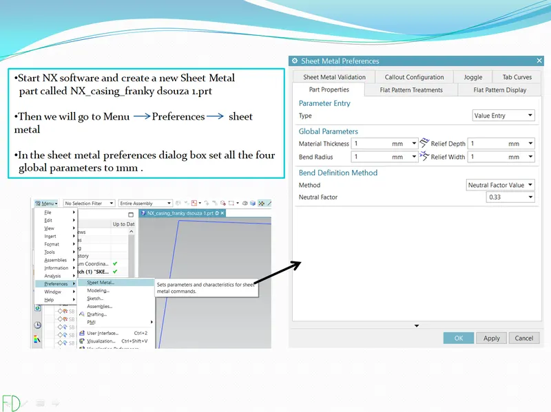
1- Setting sheet metal preference .
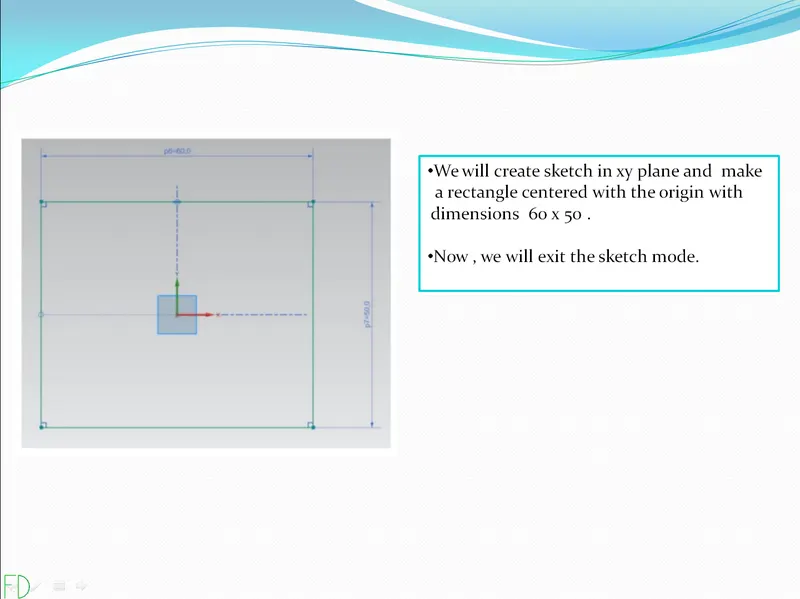
2- Creating the sketch of base tab .
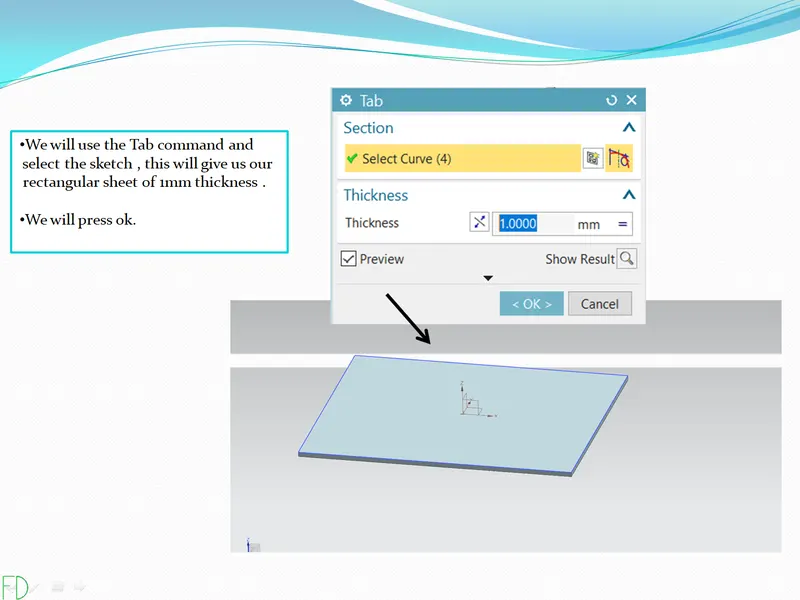
3 - Using tab command.
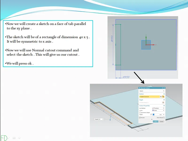
4- Creating normal cutout .
5- Bending the sheetmetal .
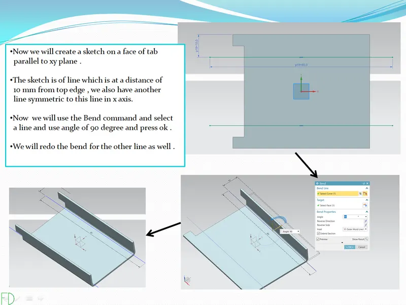
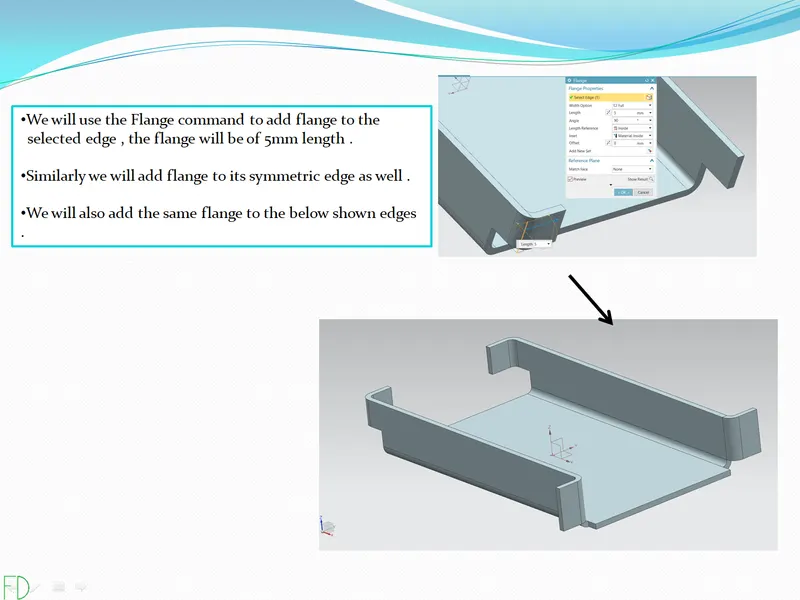
6- Creating flanges .
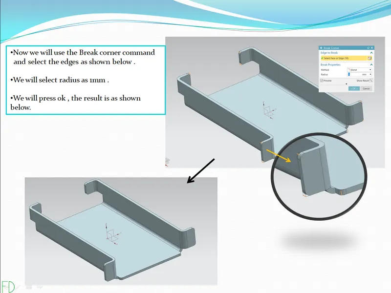
7- Adding break corner .
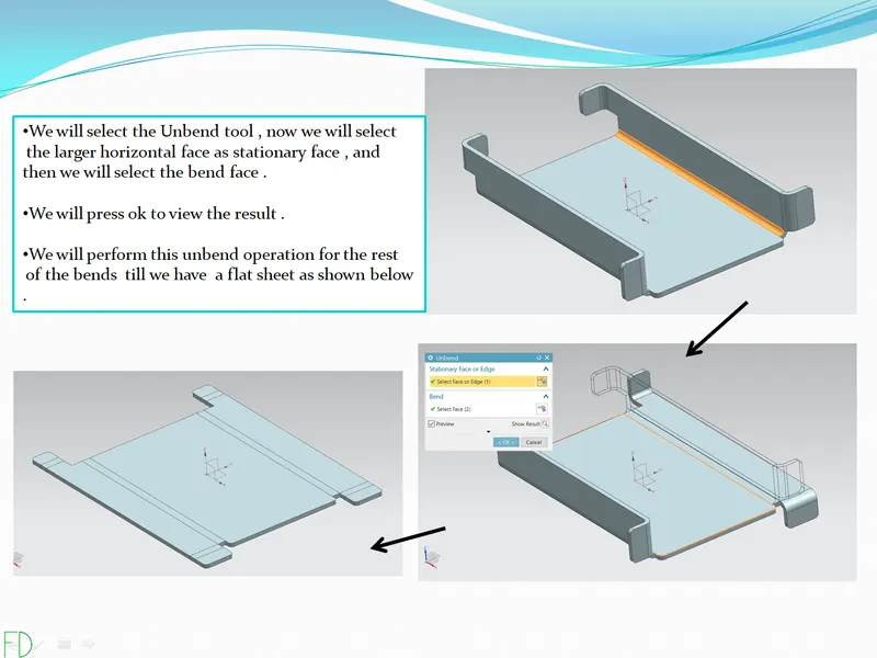
8- Unbending the part .
9- Creating holes .
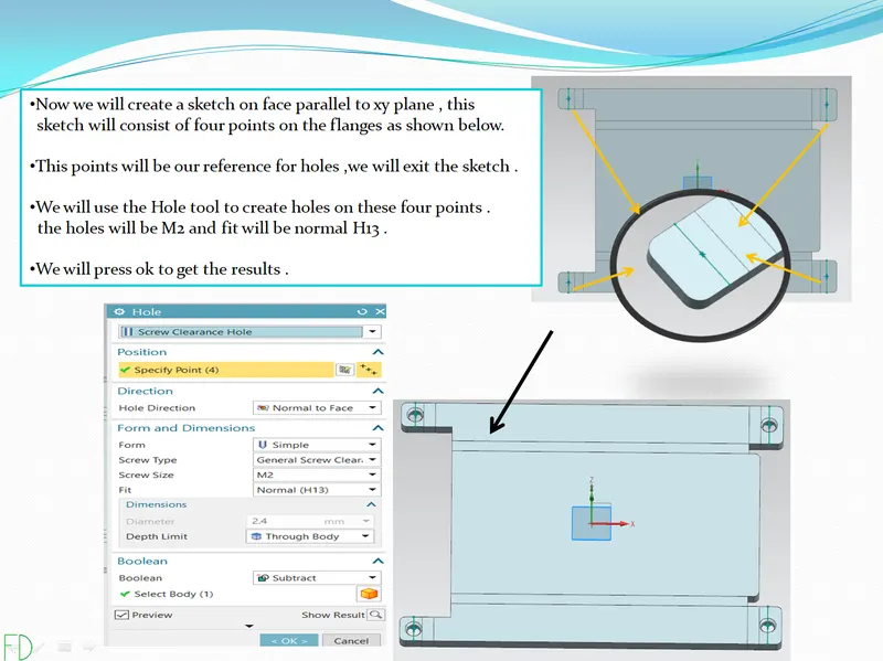
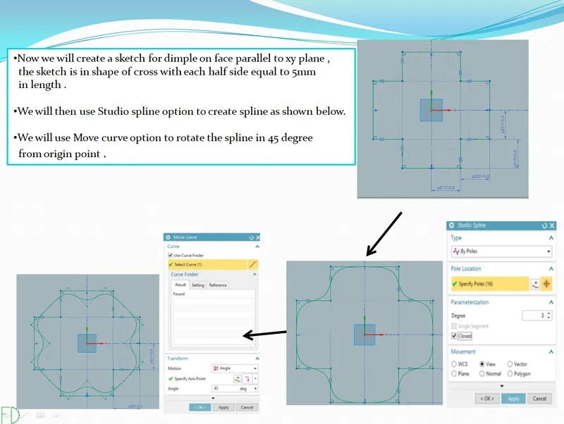
10- Creating sketch for dimple .
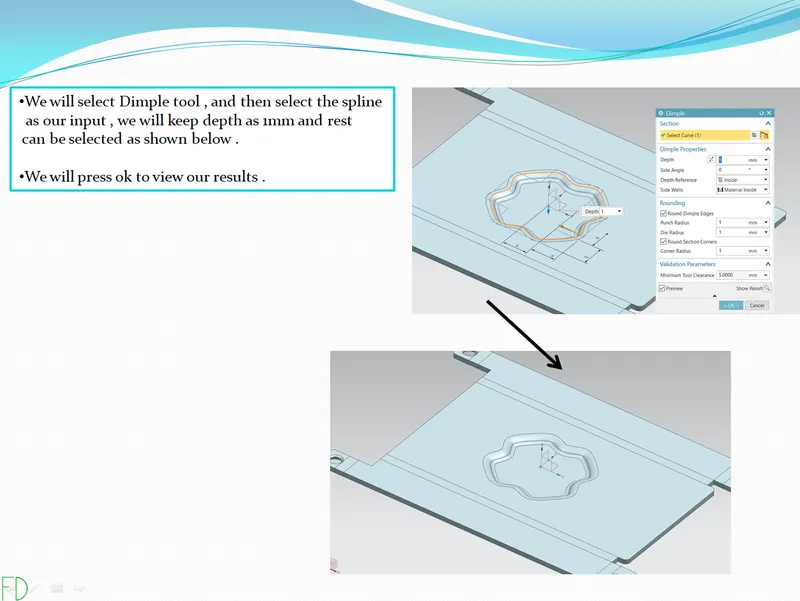
11- Creating dimple.
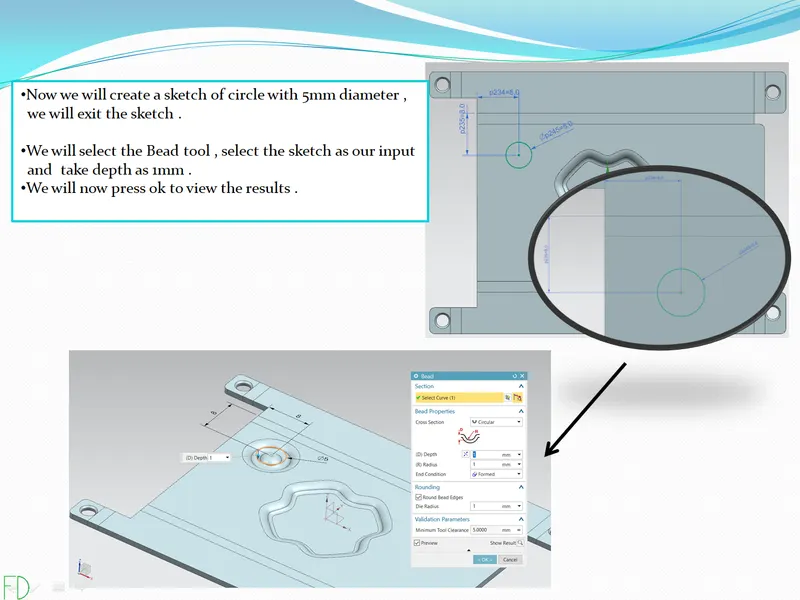
12- Creating beads .
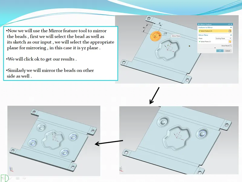
13- Mirroring the beads .
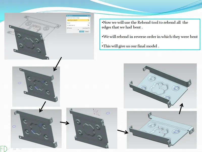
14- Rebending the part .
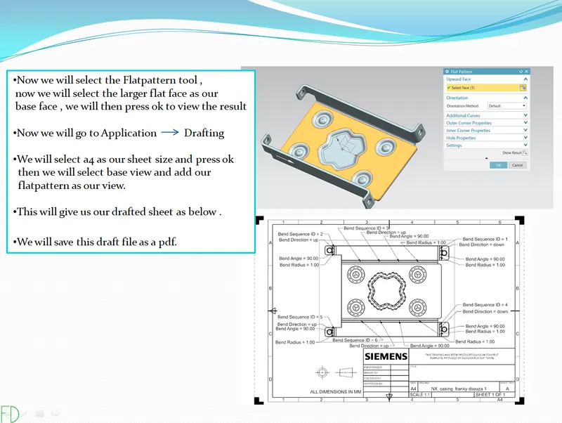
15 - Creating flatpattern and drafting .
16 - Top view .
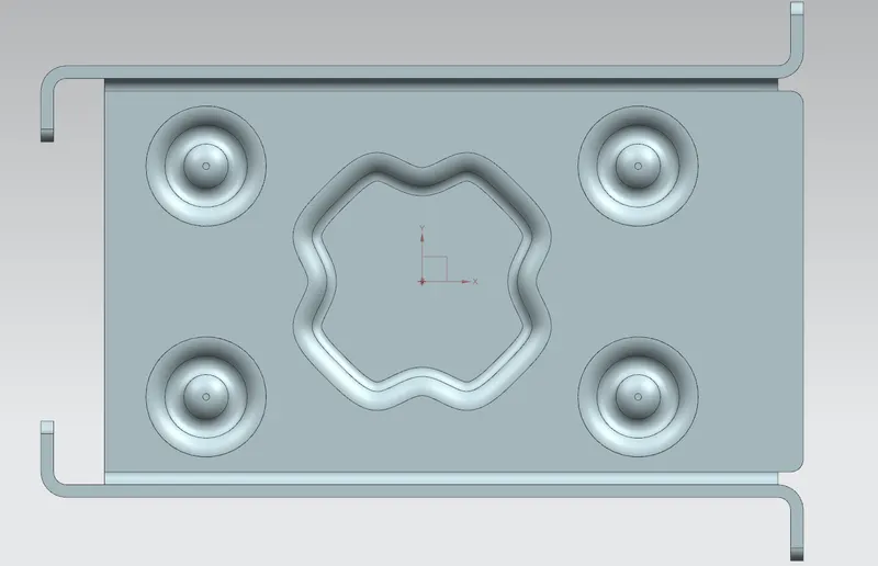
17- Front view.
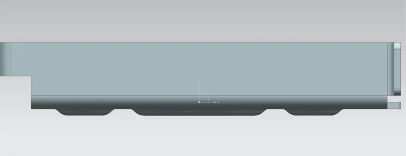
18- Side view .
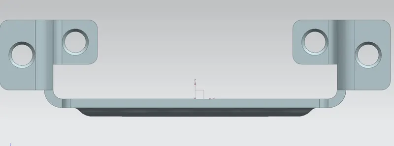
19 - Isometric view .
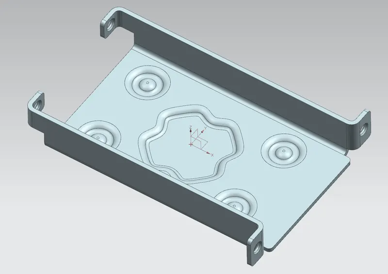
20- Drafting sheet .
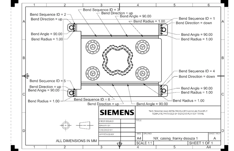
DESCRIPTION -
1 - TAB COMMAND - 
This command is used to create a base feature by extruding sketch along vector by a certain thickness value or by adding material to existing faces and bend regions of sheet metal parts .
2 - NORMAL CUTOUT - 
This command is used to cut material by projecting a sketch onto a model and then cutting perpendicular to the faces intersected by projection .
3 - BEND - 
This command is used to bend the material using a sketch as input line for bend . bend is given considering the K factor , bend radius .
4 - FLANGE - 
This command is used to add a flat flange at an angle to planar face and add a bend between the two .
5 - BREAK CORNER -
This command is used to round or chamfer sharp corners of tab or flange .
6- UNBEND - 
This command is used to unbend the material to create a flat sheet .
7 - HOLE - 
This command is used add hole in sheet metal body . this holes can be clearance for bolts, screws etc .
8 - STUDIO SPLINE - 
This command is used to create spline in sketch. this spline can be created taking points as reference .
9- MOVE CURVE - 
This command is used to move the selected curve in horizontal , vertical or it can also be rotated .
10 - DIMPLE -
This command is used to create an identation in sheetmetal part using sketched section as input for dimple . it can lift the area of model inside a sketch that simulates a stamping tool .
11 - BEAD - 
This command is a stiffening deature . it stiffens the sheetmetal . it is used to lift the material along contour of sketch that simulates stamping tool .
12 - MIRROR FEATURE -
This command is used to mirror or duplicate a part along a plane.
13 - REBEND - 
This command is used to bend the sheetmetal part that we had previously bend .
14 - FLATPATTERN - 
This command is used to create the 2D drawing of the sheet metal part .
15 - DRAFTING - 
This command is used to create drafting or detailed drawing of sheetmetal part .
CONCLUSION - The sheet metal casing is created using the tools of NX cad .